This is an individual project; your work must be your own. (The "no code" rule described in the "General Information" document applies here.) Submit a solution by 11:59pm on Friday, 10/2. Your submission directory, called proj1, should include a file named assembler.c plus all other source files necessary to build an executable version of your program. It must include a file named Makefile such that running the make program will produce an executable file named proj1.
You have three grace days to apply toward late project submissions over the entire term. Don't use them all at once. Start early. When you get confused, ask for clarification. Get easy pieces working and then move forward.
Additional activities relating to this project will include online contributions of questions and answers about project specifications, and milestones (in the Tuesday/Wednesday lab sections) where you demonstrate progress on the solution program.
You are to write an assembler that translates a CAL16 assembly language program into machine language, and in addition produces information about symbols used in the program.
You have just been introduced to the machine architecture for the MIPS computer, a real-life computer that grew out of David Patterson's RISC project here at Berkeley and John Hennesey's MIPS project at Stanford. (The Sun SPARC architecture is even closer to the Berkeley RISC.) All the things a computer can do are defined by its instruction set, which includes instructions that, among other things, do arithmetic, make comparisons, and control the execution flow of a program. The MIPS instruction set architecture (ISA) also includes registers, special machine storage in which operands to machine instructions are held. MIPS machine instructions are represented in binary as 32-bit words. As you have seen, binary values are very painful for humans to work with (you can't even print them without translating them to characters first). An assembly language is essentially a human-readable version of a machine language. It represents each instruction in an English-like form, and an assembler "assembles" each of the parts of assembly language program into its machine language counterpart. It is essentially a 1-1 translation of a textual form of instructions and static data into its binary form.
As a starting point, we will consider a machine architecture designed especially for CS 61CL, namely the CAL16. It's much simpler than the MIPS. Each step of the process that turns assembly language text into a runnable program is thus simpler and more accessible than its counterpart on a real-life computer. In this project, you'll implement the first step in the process, namely the translation of CAL16 assembly language to machine language format. You don't need to worry about what each instruction does at this stage; we'll spend lots of time later on that. For now, we're just going to translate the human-readable format to an ASCII version of the corresponding machine language.
An important aspect of an assembler is its handling of labels. Keeping track of the value of each label involves storing them in a symbol table; you've had practice with various parts of this process in earlier lab exercises and homework. In particular, you must correctly handle forward references, uses of a label before it's defined. A second part of this project is output of the symbol table.
A CAL16 program is stored in a file whose name ends in ".c16". Each line of a CAL16 assembly language program may contain the following:
Each label is a letter followed by a series of "symbol characters", that is, letters, digits, or the underscore ('_') character, followed by a colon (":").
Each instruction is terminated by a ';', with no whitespace separating the last operand from the ';'.
Whitespace may but need not follow the ':' in a label or the ';' terminating an instruction.
Each comment starts with the pound-sign character ('#') and continues to the end of the line.
The rules above define all legal lines. You may assume that your program will be given only legal input.
Each instruction consists of an instruction name (opcode) followed by operands; the number and format of the operands depend on the instruction. There is a special "pseudo instruction" .data that permits the declaration of static variables. The allowable instructions are the following.
	add   destreg  op1reg  op2reg;
	and   destreg  op1reg  op2reg;
	or    destreg  op1reg  op2reg;
	xor   destreg  op1reg  op2reg;

	addi  destreg  opreg  signedint4;
	rotr  destreg  opreg  unsignedint4;

	st    destreg  signedint4(opreg);
	ld    destreg  signedint4(opreg);
	jr    destreg  signedint4(opreg);

	bneg  destreg  labelsymbol;
	bz    destreg  labelsymbol;
	lhi   destreg  labelsymbol;
	llo   destreg  labelsymbol;
	lhi   destreg  unsignedint16;
	llo   destreg  unsignedint16;

	jmp   labelsymbol;

	.data signedint;
Operands are preceded by whitespace and separated by whitespace. (The second operand for the ld, st, and jr instructions, even though it specifies two pieces of information, contains no whitespace.)
Each reg in the instructions above has the format $n, where n is one of {0, 1, ..., 15}. Each signedint4 is one of {–8, –7, ..., 7}, and each unsignedint4 is one of {0, 1, ..., 15}. A labelsymbol is a label without the terminating colon. Finally, signedint16 stands for a 16-bit signed integer and unsignedint16 a 16-bit unsigned integer respectively.
A label is said to label the instruction that follows. One may create multiple labels for a given instruction by putting the labels on lines by themselves.
An example assembly language program follows showing the various types of instructions, along with labels and comments. You are not expected to understand exactly what it does. You will be assembling it and other test cases into valid machine code.
# Here is a sample program.
main:				# function main
	and	$3  $0  $0;	# clear r3
	lhi	$3  counter;	# get upper address of counter
	rotr	$3  $3  8;	# move it to MSB
	llo	$3  counter;	# lower portion in LSB
	ld	$4  0($3);	# load the initial value into r4
loop:	bz	$4  done;
	or	$2  $3  $3;	# move to arg register
	jr	$1  2($3);	#
	addi	$3  $3 -1;	# decrement the counter
	st	$4	4($3);
	jmp	loop;
done:
	jmp	done;# stuck here
	llo	$13	258;
	lhi	$13 258;

counter:.data	61;
dummy:
	jr	$0  2($1);	# just return
	jmp	foo;
	.data -3;
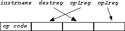
Each assembly language instruction in a file is to be translated into a 16-bit machine instruction. For the .data pseudo-instruction, the translation is immediate: the binary representation of its argument. Each other instruction has a four-bit op code (short for "operation code"), displayed in the table below, followed by operand fields that fill out the 16-bit word. The op code is the most significant 4 bits. You can think of it as the leftmost hex digit.
| instruction name | op code | instruction name | op code | |
| add | 0 | llo,lhi | 8 | |
| or | 1 | UNUSED | 9 | |
| xor | 2 | bneg | A | |
| and | 3 | bz | B | |
| addi | 4 | jr | C | |
| rotr | 5 | UNUSED | D | |
| st |
6 | UNUSED | E | |
| ld |
7 | jmp | F |
A couple of notes: lhi and lho are both the "load immediate" instruction and have op code 8. They differ in how the assembler processes their argument, as discussed below. There is no instruction with op code 9, D, or E. (Those are reserved for future use.)
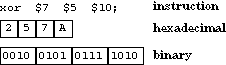
The and, or, xor, and add instructions each have three register operands. Since registers are numbered from 0 to 15, each register operand can be represented in four bits. The four-bit op code together with the twelve bits for register operands form the 16-bit machine instruction. You can think of it as four hex digits: the first is the opcode and the rest are register specifiers. A slight wrinkle here is that the operands appear in a different sequence from how they appear in the assembly language instruction, as shown below.
| R-R Format | Examples |
|
|
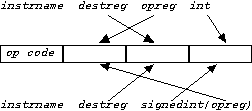
The second type of instruction treats one of the operand fields as an constant immediate value, rather than a register specifier. ("Immediate" in this context means "stored in the instruction itself" rather than accessible indirectly in a register.) Two of these instructions, addi and rotr, take three separate arguments: two registers and a small integer (small enough to fit in four bits) as arguments. The immediate operand in the addi instruction is signed; its counterpart in the rotr instruction is unsigned. In three others, ld, st, and jr, the second and third arguments are combined in the form
signedint(opreg)
The machine language representation of these instructions, however, are the same, with the destination register and the operand register switched as in instructions already discussed.
| Reg-Imm Format | examples | hexadecimal representation | binary representation |
 |
ld $12 -2($1); |
71CE |
0111 0001 1100 1110 |
The remaining instructions all involve handling of labels. Each instruction takes up two bytes (16 bits) of memory. Thus the first instruction is at address 0, the second at address 2, the third at address 4, and so on. The value of a given label, then, is the address of the instruction it labels. If a label appears as the last thing in the program—i.e., it labels an unspecified instruction—its value is 2 plus the address of the last instruction in the program. As in earlier lab exercises and homework, you'll need to maintain a symbol table that keeps track of the definition and uses of each label.
A third class of instructions are "load immediates" and branches. They combine the least significant 8 bits into an immediate value. "Load immediate" is often used for constructing a literal value in a register. In many cases, we will want to build a full 16-bit value, but there's not enough room in the 16-bit instruction to do this; four bits are used for the opcode and four for the destination register. Thus, we need to construct the literal eight bits at a time. The two assembly forms, llo and lhi, translate into the same opcode, but the former is used to insert the lower eight bits of the constant value (its rightmost eight bits) and the latter the upper eight bits (its leftmost eight bits). When the literal is a label, this would be the lower and upper portions of the address associated with the label.
Here's an example. Suppose that the symbol count labels the instruction at address 52A4. Then the llo and lhi instructions in the table below are translated as indicated.
| instruction | translation |
| llo $7 count; | 87A4 |
| lhi $7 count; | 8752 |
Branches are handled differently. Their 8-bit field is the relative distance in 16-bit words from the branch instruction to the target. (This is the same as the number of instructions from the branch to the target.) It must be in the range of –128 to 127. It is a signed value, as it is used for branching both backwards and forwards. Three examples appear in the table below.
| program segment | translation |
early: ld $12 -2($1); |
71CE |
Finally, the jmp instruction combines all three fields into a 12-bit value, which is most of the word address—bits 1-12, counting from the right—associated with the label. If the symbol done labels the instruction at address 743A (0111 0100 0011 1010 in binary), the instruction jmp done; would be translated as follows:
| binary | hexadecimal |
| 1111 1010 0001 1101 | FA1D |
Your program will be run with the command form
proj1 name.c16
where name is a nonempty sequence of non-whitespace characters. In particular, name may contain '.' ("dot" or "period") characters. (Running the make program would have produced the executable proj1.) Your program will produce two text files: name.o, which will contain an ASCII version of the corresponding machine language, and name.syms, which will contain an ASCII representation of the symbol table.
For example, running your program on a file named test.c16 should produce files named test.o and test.syms.
The format of the ".c16" file is described above. All integers in the input should be interpreted as base 10. You may assume that lines are no more than 120 characters long, and words in a line are no more than 20 characters long. You may not assume any bound on the length of the program or the number of symbols it defines. You may also assume that the program is legal according to the rules specified earlier in this document. Note: a reference to an undefined label should not be considered as an error in this context.
Each line in the ".o" file will consist of the ASCII representation of four hexadecimal digits. Use upper case for the hexadecimal digits A through F. The sample program listed above and its corresponding .o file appear below.
| assembly language | corresponding ".o" lines |
# here is a sample program |
3030 |
Each line in the ".syms" file will contain information about one of the lines in the symbol table, in the following format:
labelsymbol defined? value type1 refaddress1 type2 refaddress2 ...
where the fields in the line are as follows:
The arguments to the bneg and bz instructions do not contribute entries of any kind to the .syms file.
The value of an undefined symbol is FFFF. Any reference to an undefined symbol in lhi, llo, and jmp instructions should be assembled into a sequence of 1's of the appropriate length.
There may be any number of type-refaddress pairs. For example, an unreferenced label will have none. Lines in the .syms file should be ordered alphabetically by symbol name, and type-refaddress entries for a given symbol should be output in increasing order by refaddress.
All addresses are four hexadecimal ASCII digits, with hexadecimal digits A through F output in upper case. Consecutive fields in the output line are separated by a tab character.
The sample assembly language program given above would thus yield a ".syms" file with six lines:
	counter	y 001C lhi 0002 llo 0006
	done	y 0016 jmp 0016
	dummy	y 001E
	foo	n FFFF jmp 0020
	loop	y 000A jmp 0014
	main	y 0000
Your assembler will read a text file containing assembly language instructions. It will go through the file line by line. It will discard the comments, locate all the label declarations, and parse the instructions and data statements. It will translate each instruction into the equivalent binary machine code representation. This will involve translating the textual representation of integers into binary values, but also translating each label into the memory address it represents. How do you know what address is associated with a label? You have to construct a representation of all the instructions and data. Most assemblers run in two passes, first parsing all the instructions, building a skeleton of each, and finding all the label declarations and uses, then going through and resolving all the labels to their values.
How do you tackle a hard problem? Divide and conquer. Don't try to write your project as a huge monolith of code. Break it into pieces that do simple things well. Think about what you have in hand already. You have tools that read files and build data structures containing the lines as strings. You have built scanners that run through strings and pull out comments or labels or words. You have built repositories that collect a bunch of symbols and information about them. You can insert new ones and lookup old ones. You know how to build arrays of things and lists of things, and the things can be anything—chars, ints, structs, arrays, lists. And you have translated from strings to numbers. So you have all the pieces. Now we want to orchestrate these abstractions to parse assembly language files and produce machine language files.
We hope that your previous programming experience has taught you to develop your program in manageable pieces, and to add functionality only when you're sure that you're building on a foundation of correct code. We encourage you to make use of code you encountered or wrote earlier in this course.
Some suggested approaches:
The following summarizes the binary machine format. It has
sixteen instructions, each a 16-bit word. The word can be viewed
as
four 4-bit fields. Some instructions combine the last two into an
8-bit field, one combines all three into a 12-bit field. The mnemonic
is the assembly language version of the opcode. Later we will
explance the Register-Transfer level semantics in this table. For
now we are just concerned with translating the human-readable assembly
language into a representation of the machine-readable, binary format.
| OP | Q2 |
Q1 |
Q0 |
MNE | Semantics | ||
| 0 | a | d | b | add | R[d] := R[a] + R[b] | PC := PC+2 | |
| 1 | a | d | b | or | R[d] := R[a] | R[b] | PC := PC+2 | |
| 2 | a | d | b | xor | R[d] := R[a] ^ R[b] | PC := PC+2 | |
| 3 | a | d | b | and | R[d] := R[a] & R[b] | PC := PC+2 | |
| 4 | a | d | off4 | addi | R[d] := R[a] + Sx(off4) | PC := PC+2 | |
| 5 | a | d | off4 | rotr | R[d] := R[a] rot off4 | PC := PC+2 | |
| 6 | a | d | off4 | st |
Mem(R[a] + Sx(off4)) := R[d] | PC := PC+2 | |
| 7 | a | d | off4 | ld |
R[d] := Mem(R[a] + Sx(off4)) |
PC := PC+2 | |
| 8 | a | off8 |
ldi | R[a] := 0||off8 | PC := PC+2 | ||
| 9 | |||||||
| A | a | off8 |
bneg | PC := (R[a] < 0) ? PC + (2 * Sx(off8)) : PC+2 | |||
| B | a | off8 |
bz | PC := (R[a] == 0) ? PC + (2 * Sx(off8)) : PC+2 | |||
| C | a | d | off4 | jr | R[d] := PC | PC := R[a]+Sx(off4) | |
| D | |||||||
| E | |||||||
| F | off12 |
jmp | |
PC := (PC & 0xE000) | (2 * off12) | |||
R is a 16-element array of registers. PC is the program counter, the address of the currently executing instruction. Mem is the memory array, one element per byte. Sx is a sign-extending function. Given a four-bit signed value, it returns the equivalent 16-bit value.
Register $0 is assumed always to contain 0. It is thus read-only.
An attempt to load $0 from memory or from a computation has no effect.
Q. Is it possible to have the following:
	loop: #this is a loop
	do something;
A. Yes. You may also have
	#this is a loop
	loop:
	do something;
and
	loop:
	#this is a loop
	do something;
Q. Must comments strictly follow instructions?
A. If a line contains both an instruction and a comment, the comment
must follow the instruction. If a line contains both a label and an
instruction, the instruction must follow the label. If a line contains
both a label and a comment, the comment must follow the label. If a
line
contains all three, the comment must follow the instruction, which must
follow the label. Comment is from # to the end of the line.
Q. May I assume that an instruction always appears on the same line as or on the line immediately following a label?
A. No. Any number of comment or blank lines may separate a label from the instruction it labels.
Q. If I understand correctly, having more than one instruction per line separated with a semicolon, e.g.
and destreg op1reg op2reg; or destreg op1reg op2reg;
is illegal? So we can assume that each line will contain at most one semicolon?
A. That's correct.
Q. Will every program start with the label "main:"?
A. No. The name "main" is totally arbitrary for the purposes of project 1. You might instead have
	count:
		instruction
	main:
		instruction
so that count would have value 0 and main value 2. The program might even start with an unlabeled instructions.
Q. How do we know which label is assigned to which address?
A. You have to keep track, as you read through the file, which address you're currently working on. The address of the first instruction is 0, the address of the second instruction is 2, and so on. The address that a label represents is the address of the first instruction after the label.
Q. Why is counter marked line 14 (28 in memory) when it's on line 15?
A. That's because main doesn't count as an instruction so you have to start counting from the second line, making it line 14. Only instructions increment the address.
Q. Why does the assembler have to make two passes? Is there a way to simplify this into one pass?
A. It is helpful to make two passes, one that first parses all the instructions, building a skeleton of each, and finding all the label declarations and uses, then goes through and resolving all the labels to their values. This makes it simpler. It could be done in one pass but you have to keep track of prior uses and patch them up as you go. Trying to do two things at once will lead to harder-to-find bugs and harder-to-debug code.
Q. Do you think it's all right to use the supplied homework solutions in the project?
A. Yes. That's why we're supplying them: to give you a model of reasonable code, and to save you some time.
Q. Would you be allowed to use someone else's code from homework 3 as long as they are okay with it and you document it?
A. No. The code in your project submission should be either yours or ours. Using the code of your classmates or previous CS 61C students violates the "no-code" rule (see the "General information" document) and will get you into big trouble.
Q. I don't understand how a jump to the address 743A (0111 0100 0011 1010 in binary) is translated to machine language as FA1D.
A. First, the byte address 743A is converted to a word address by shifting it right one bit position. (As in MIPS, this conversion takes advantage of the fact that any instruction is aligned to a word address, so if the rightmost bit were kept, it would always be 0.) 0111 0100 0011 1010 shifted right one bit is 011 1010 0001 1101. The last 12 bits of the assembled jump instruction is then 1010 0001 1101; the first four bits is the op code for the jump, namely F.
Q. If an attempt is made to change the value of $0, should we ignore it or give out an error?
A: Storing into register $0 is a perfectly good "no op".
Q. Will the C16 binary run only on the Sun machines?
A. The output of the assembler is two ASCII files, not "binary".
Think of it as human readable binary.
Q. The printf function prints hex in only lower-case letters, but the project requires upper case. Can we disregard that?
A. No, you may not disregard the requirement for upper-case hex digits. You may, however, use the format specification X instead of x to get your hex values printed in upper case. (See K&R, page 244.) Here's an example:
	unsigned short x = 0xABC1;
	printf ("%hX\n", x);
Q. Is CAL16 assembly language the same as MIPS?
A. There are numerous differences, including the following.
Q. Why is it that the operands in an instruction written in the CAL16 assembly language are listed in a different order in hex?
A. This will become clear when you actually design the CAL16 CPU later in the course.
Q. How do lhi and llo work?
A. There are two forms of the lhi and llo instructions. In one form, their second argument is a label. That label represents a two-byte address, so lhi is assembled into a "load immediate" machine instruction whose second operand is the first of those two bytes, and llo is assembled into a "load immediate" instruction whose second operand is the second of those two bytes. In the second form, the second argument is a two-byte number. That value is translated to hex, and then handled as if it were an address in the first form of those instructions.
Don't be too concerned right now about how these instructions work. Just translate them according to the specifications. Since they have the same opcode, the instructions can't differ in functionality. Both instructions load their lowest byte into the lowest byte in the destination register. In order to assemble the full 2-byte value, it's possible to subsequently rotate the register containing upper byte right by 8-bits to get it to the correct location and then load the lower byte into the same register, as demonstrated in the example program.
Q. What does .data do?
A. The .data instruction differs from the MIPS .data instruction. It doesn't say any thing about what segment the code should be put in; the CAL16 architecture only has one segment. The .data instruction merely gives you a way to put an arbitrary two-byte quantity into the next word. It says nothing about how that word will be treated when the program is run. Consider, for example, a program that starts with an add $5 $0 $0, and follows it immediately with the instruction .data 5297. The add would be the first instruction to be executed, and then the instruction whose decimal value is 5297 would be executed. (The latter turns out to be an or instruction.
Q. The spec says, "You may not assume any bound on the length of the program", but the C16 architecture uses only 16-bit addresses. If assembling a program goes past the end of the address space by producing more than 64KB of machine code, what should the value of subsequent labels be?
A. There are some limits on code, but the program could have LOTS of
comments.
Q. Are we not expected to handle jumps of more than 128?
A. The bneg and bz instructions are limited to jumping a distance of -128 to +127 words (-256 to +254 bytes). However, there is also a jmp instruction that has a larger range: its target can be any address with the same top 3 bits as the current PC (e.g., from address 0x7654 a jmp could go anywhere from 0x6000 to 0x7FFE). And you can jump anywhere in the address space by using a jr instruction.
Q. From the spec: "A reference to an undefined label should not be considered as an error in this context. " What should we do with the undefined label? Since we need to print out the relative address for any reference to the defined labels. Are we supposed to leave the line blank?
A. An undefined label should be treated the same as a defined label, except that its corresponding address is FFFF.
Q. Why do the bz and bneg instructions not contribute entries?
A. The symbol table is used by the linker to arrange multiple modules in memory. The linking process involves actually replacing the contents of some instructions; we'll explain how in a couple of weeks. Since the argument for a branch is a relative address, as opposed to a jump's argument, which is an absolute address, branches don't need to get fixed up during linking.
Q. The project description says, "The arguments to the bneg and bz instructions do not contribute entries of any kind to the .syms file." But what if I have something like "bz $4 done", and this is the only place where the symbol "done" is used. Does it contribute the entry "done n 1234" instead of "done n 1234 bz 0050", or does it contribute no entry at all?
A. If the symbol "done" is never defined anywhere in the program, the bz that uses it will not contribute any symbol table entries. (Actually that's a situation that you don't have to worry about.) If "done" is defined somewhere, the definition will appear in the table, but the use by the bz will not.
Q. The specification says (in the "Input and output format" section) that "any reference to an undefined symbol in ld, st, ... should be assembled into assembled into a sequence of 1's of the appropriate length." But none of the arguments to ld and st are symbols.
A. Correct. I fixed the problem specification.
Q. What's a good implementation for the symbol table?
A. You don't need to do anything fancy. A simple expandable array or linked list is fine.
Q. Will the project be submitted normally as "submit proj1" on instructional computers. Also, will there be an autograder for this project that we can use to test?
A. You will use the "submit" command on the instructional computers to submit your project 1. A test script will appear shortly.
Q. Should we write in C or assembly language?
A. C.
Q. What will this project teach us?
A. A C program gets compiled to assembly language, then assembled. The assembled version gets linked with other modules to produce an executable program. This project is an in-depth introduction to the assembly stage. Later in the course, you will write some of a CAL16 linker and encounter a CAL16 interpreter, as well as writing a MIPS interpreter for project 3.