CS 150 Spring 1997 Quiz
2 Solutions
NOTE: These are just one example of solutions to the quiz. Different
answers also be correct.
1. (a) Convert the BCD coded number below to equivalent decimal
form:
1000 0111 0110 0010.0110 0101BCD = 8762.6510
(b) Convert (271.A)16 to (i) Base 2 and (ii) Base
8 equivalents.
(271.A)16 = 0010 0111 0001 . 10102
001 001 110 001 . 101 02 = 1161.58
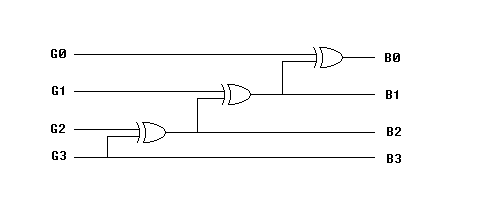
(c) Design a circuit for converting a 4-bit Gray into its binary equivalent.
You may use AND, OR, XOR, or inverter gates only. Use
as few gates as possible.

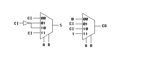
(d) Implement a 1-bit full adder using a minimum number of 4-input
control-line multiplexers and inverters only. An inverter counts
as 1/5th (20%) of a MUX. Assume complements are not
availiable.

2. (a) Describe the function and characteristics of the counter
circuit (diagram omitted):
It is a 10-sequence counter that goes through the sequence Q1 Q2 Q3 Q4
= 0000, 1110, 0110, 1011, 0011, 1010, 0010, 1100, 0100, 1000, which translates
into 0, 7, 6, 13, 12, 5, 4, 3, 2, 1 (with Q1 as the least significant bit).
It counts down from 7 to 0 except for the case of 13 and 12. Very
few people got full credit.
(b) A JN flip-flop has two inputs, J and N.
Input J behaves like the J input of a JK flip-flop, and N behaves like
the complement of the K input of a JK flip flop (i. e. N = K').
(i) Obtain a characteristic table of the JN flip-flop:
| J
|
N
|
Q+
|
| 0
|
0
|
0
|
| 0
|
1
|
Q
|
| 1
|
0
|
Q'
|
| 1
|
1
|
1
|
(ii) Proof of characteristics with two inputs connected:
In a JN flip-flop, Q+ = JN + JN'Q' + J'NQ, but if N=J=D (the two inputs
J and N become D), then
Q+ = DD + DD'Q' + D'DQ = D, which matches the D flip flop's characteristics.
(3) As usual, for the following problems, be sure to state
all assumptions clearly.
(a) Obtain the reduced flow table for the primitve flow table
(not shown here).
| 00
|
01
|
11
|
10
|
| 1
|
5
|
3
|
2
|
| 1
|
-
|
-
|
2
|
| -
|
5
|
3
|
2
|
| 4
|
5
|
-
|
-
|
Stable states are boldfaced. The idea is that one way to merge states
is through reduction and merging.
The question only asked for reducing equivalent states (combining states
which are stable in the same
column). This also keeps the reduced flow table primitive.
Thus, states 3 and 6 were reduced, and then
states 1 and 4 were reduced. Since outputs were not given, it should
have been assumed that states 1 & 4,
and 3 & 6 had the same outputs. Most people merged the table
into one or two states, which was wrong.
(b) Obtain the primitive flow table for a negative edge-triggered
T flip-flop. Consider T as a regular input, C as its clock input,
and Q as its output. Do not merge the table.
Input = T, C
Output = Q
Stable states are in boldface
| 00
|
01
|
11
|
10
|
Q
|
| A
|
B
|
-
|
D
|
0
|
| A
|
B
|
C
|
-
|
0
|
| -
|
B
|
C
|
H
|
0
|
| A
|
-
|
C
|
D
|
0
|
| E
|
F
|
-
|
H
|
1
|
| E
|
F
|
G
|
-
|
1
|
| -
|
F
|
G
|
D
|
1
|
| E
|
-
|
G
|
H
|
1
|
The easiest way to do this problem is to have 4 states for Q=0 and 4 for
Q=1. Notice that the only
time Q switches values is when T is high and C goes from 1 to 0 (negative
edge), which corresponds
to input going from 11 to 10. At all other times, it stays within
its group of 4 states.
(c) Design a circuit that outputs a short pulse on output Z each
time an input variable, X,
makes a 0->1 or a 1->0 transition. Use as few states as
possible. Show the next state and
output equations for your circuit in as compact form as possible.
The problem doesn't state whether to do this synchronously or asynchronously,
so either was acceptable, as long as it was clearly stated. Otherwise
it was assumed to be operating asynchronosly. There were many ways
to do this, one of which the following:
NS0 = Z' PS0 + Z X
Z = X xor PS0
which could be implemented with a mux like this:

But note that the obvious way shown below doesn't work because there
is no feedback
and this is a sequential circuit.

(d) Obtain a race-free state-assignment for the merged flow
table shown opposite, using as few additional states as possible.
Be sure to include a transition graph. List all codes. Assume
the outpus are such that no further merging is possible. Assume the
outputs can be chosen to avoid glitches.
Since outputs could be chosen, the best way to do this was to add no additional
states and reuse the original states as transition states instead of adding
more. States 1 & 2 are relabeled A, 3 & 6 became B, 4, 7
& 8 became C, and 5 became D.
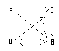
Transition graph:

State Codes:
A = 00, B= 11, C=01, D=10
The resulting flow table would look like the following (stable states in
bold):
|
|
00
|
01
|
11
|
10
|
| A(1,2)
|
A
|
A
|
D
|
C
|
| B(3,6)
|
C
|
B
|
B
|
D
|
| C(4,7,8)
|
C
|
B
|
C
|
C
|
| D(5)
|
B
|
A
|
B
|
D
|
The race from A->B on input 11 goes through transition state D and the
race from D->C on input 00 goes through transition state B.


