| Home | Assignment 1 | Assignment 2 | Project 3 | Project 4 | Project 5 |
We improved on our Project 4 raytracer. Below is a list of the main new features
There are several new custom commands used in our input files:
| Command syntax | Example | Description |
|---|---|---|
| arealight x y z w h r g b | arealight 0 0 5 2 3 1.0 1.0 1.0 | The arealight command adds a rectangular area light source, as opposed to the circular area light source by the point command. The light is always oriented on the xy plane; to orient it another way you must use transforms. The width parameter is the width along the x directiona, and height refers to the y dirrection. It is suggested that you do not use scaling transforms (i.e. don't make area light sources with w/h of 1/1 and then scale them to whatever you need them to be) becuase the jitter matrix is generated based on the width and height; if you were to scale the light it may become biased in one direction. The example creates a white area light source 5 units off the ground with a width and height of 2 and 3. |
| gridsize size | gridsize 4 | This changes the resolution of the grid used to accelerate ray-object intersection tests. A more detailed scene will be better off with a finer grid; the opposite applies for a large scene. However, do not make the grid size too small or you will incur too much overhead. You may also run out of memory - the grid is not hierachical so decreasing the gridsize by a factor of 2 has the effect of increasing memory consumption by a factor of 8. The default grid size is 1. The example sets the gridsize to 4. |
| rIndex r | rIndex 1.5 | This sets the refractive index for objects following this command, determining how an object refracts light. This only affects objects that have a non-zero transmittance. The example sets the refractive index to 1.5. |
| transmittance r g b | transmittance 0.5 0.2 0.2 | The transmittance command determines how transparent, or refractive, a surface is. The r g b parameters range from 0 to 1. A transmittance of 0 means the surface does not transmit any light of that color. A transmittance of 1 means that surface will transmit light of that color without loss. For example, transmittance 0 0 0 would be an opaque object, while transmittance 1 1 1 would be a perfectly clear surface. The example describes an object that transmits red better than green or blue. |
| focus f | focus 4.5 | The focus commmand determines how far in front of the camera the focus point for depth of field effects is. Everything closer or farther away than the focus point will look blurry. The example sets the focus point 4.5 units away from the camera. |
| lensSize w | lensSize 0.5 | The lensSize command determinse the size of the lens for depth of field effects. A larger lens results in more exaggerated blurriness. A lens size from 0.1 to 0.7 is probably realistic depending on the scene. A lens size of 0 results in no depth of field effects. In this example, the lens size is set to 0.5. |
| enableTextures | enableTextures | This command enables textures to be drawn on the following surfaces. If the currently bound texture is invalid, it will use the diffuse color. |
| disableTextures | disableTextures | This command disables textures to be drawn on the following surfaces. The diffuse color of surfaces will be the diffuse color specified normally. |
| bindTexture id | bindTexture 2 | This command binds the active texture id. When you bind a texture id, you can then load a texture into that id (possibly overriding existing texture data) and use it to texture objects. The example binds the texture id 2. |
| loadTexture file | loadTexture wood1.png | This command loads a texture into the currently bound texture id. The file can be of any format that is supported by Java's javax.imageio.ImageIO image utility class, which includes PNGs, JPGs, BMPs, and more. The example loads a texture from a file called wood1.png. |
| texcoordTriangle Sa Ta Sb Tb Sc Tc | texcoordTriangle 0 0 0 1 1 0 | This command specifies the texture coordinates to use when texturing a triangle. The first pair of coordinates coorespond to the first vertex specified in the tri command, etc. If the coordinates are outside of the range 0-1, they will wrap and/or tile. |
We have implemented some new features and changed some of the old features.
Performance Optimizations:
We implemented several performance optimizations.
First, the most effective optimization was the use of an acceleration
grid. The grid is comprised of uniform, axis-aligned boxes that cover
the entirety of the scene, including lights and the camera. Before
rendering starts, for each object in the scene, we determine which grid
boxes it occupies, and note them down.
When we are tracing rays, we first find which box the ray starts in.
Then, we do intersection tests for all objects within that box that are
not marked. Once we do an intersection test with an object, we
mark it so we don't test for it again. If there is an intersection, we
pick the closest one and halt (actually, we check if the intersection
occured within this box; otherwise we proceed until we pass the
intersection point). Otherwise, we determine which box we go to next by
looking at the direction of the ray. The same process is repeated. If we
reach the other side of the grid without an intersection, we return no
intersection. Since traversing grid boxes is fast for empty boxes (to a
degree), we are essentially only testing objects within the vicinity of
the ray's path, and furthermore we are testing the closest objects
first.
There are several disadvantages to our grid structure. First, it is not
hierachical, so a large scene with a small grid size will result in high
memory usage. Also, because it is not hierachical, traversing many
empty boxes can consume lots of compuatational power if there are many
boxes.
Becuase of the possible high memory usage, it is recommended you run the
program with the -Xmx argument to increase the maximum java heap size.
For example, -Xmx1000M will ensure the java VM has at least 1 gigabyte
of memory to use.
We also optimized the intersection tests heavily. Since we are using
Java, the biggest slowdown is object creation, especially if these
objects are simply 'intermediate' objects used in the course of a
calculation. This is becuase in Java, there is the obvious heavy
overhead for allocation and initilization of an object, but there is
also a heavy overhead for the garbage collection of objects. This second
point manifests itself much more prominently when you are running with
many threads - all threads must halt while the garbage collector is
running. On a quad-core machine, our project 4 submission, running with 4
threads, utilized anywhere from 60-80% of the CPU. With our
optimizations, now it almost never drops below 95% for most scenes.
Refraction:
We implemented refraction.
The basic refraction is simple - it follows the physics laws based on
the refractive index. It assumes that once you enter an object, you must
exit from the inside of another surface. Spheres and cylinders capped
with circles work well for this but if you do something with triangles,
you must be careful to have no holes in your object.
Because it doesn't make sense for a transparent object to cast a solid
shadow, we changed the shadow algorithm a bit. If the shadow ray passes
through a transparent object, it does not change its path but it takes
it into account. This results in transparent objects casting lighter or
colored shadows. We do not have anything complicated like caustics.
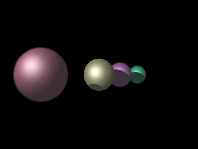
Depth of field:
We implemented depth of field.
The idea is simple - instead of casting rays straight out, cast them so
they focus at a certian point in the distance. Thus, objects close to
you and far away will be hit by rays belong to pixels that wouldn't
normally hit them. This results in a blurry effect.
Becuase we must cast multiple rays per pixel to achieve this effect, it
is closely tied to our AA implementation. Thus, a higher AA level will
also result in a nicer DOF look.
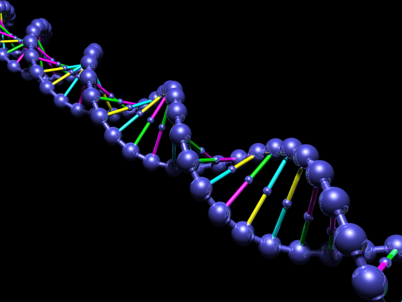
More primitives:
We added a few more primitives.
Cylinder - This was almost identical to a sphere, except it did not have
a z-dependance so the equations needed to be modified slightly.
Circle - This was a very simple primitive - you test for a plane
intersection, then see if the intersection point is a certian distance
from the center of the circle.
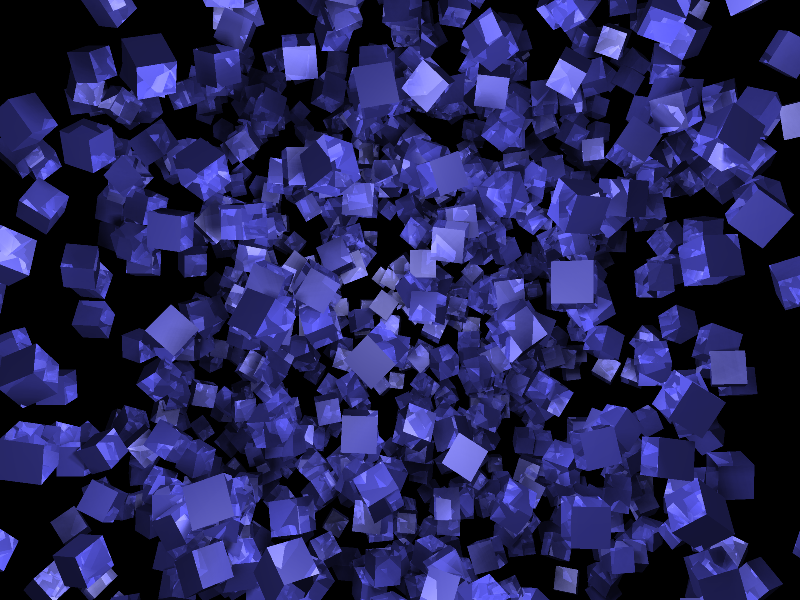
Box - This is easy if the box is axis aligned, so we did that,
transforming the ray beforehand and afterwards. You check for
intersections on all 6 planes represented by the sides of the box and
then choose the best one
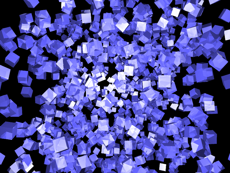
Textures:
We added texture support.
We did not implement any fancy sampling or filtering - we left that to
the AA to take care of. So our texturing model is very simple - the
intersection contains information about where on the surface it hit. For
a triangle, it would be the u/v/t coordinates, for a box, it would the
x/y cooridnate and the face of the box. We then do a simple lookup into
the pixels of the texture and return the color. For wrapping, we simply
take the modulus of the s/t coordinate.
Texturing details:
Triangle - it is simple bayesian interpolation from the calculated u/v/t
coordinates.
Sphere - the angle around the Z axis (going around the circle) and the
angle of elevation (going up/down) determine the s/t coordinates.
Cylinder - same as the sphere, but the z-coordinate (if the cylinder was
oriented along the Z axis) determines the t coordinate.
Box - It is extremely simple to calculate the s/t cooridnates from the
x/y coordinates of a face. Then, we determine which face the ray hit.
The texture for a box is comprised of 6 images, one for each face, each
stacked on top of each other in a single image file.
Lighting:
We made some minor changes to the lighting algorithm.
We added a rectangular area light, which is almost identical to the
circular area light except its jitter matrix has points spread out in a
rectangle rather than a circle.
We also fixed the small specular problem - we were doing the
calculations correctly but we did not take into account that the normal
dotted with the halfangle would sometimes be positive even if we were
looking at it from the wrong side.
We also made ambient light a little more realistic - it acts as a
diffuse light source now, rather than simply adding its color to the
final color calculated. That is to say, textures will show up in ambient
lighting now.