CS184 AS3: Model and Scene Hierarchy
DUE DATE: Friday February 11th, 11:00pm
Aim
In this assignment you will build an animated, hierarchical scene and
then render it with dynamically computed bounding boxes.
This will expose you to the following concepts:
- Matrix stacks to define transformations which place objects in a scene
- Scene graphs for efficient hierarchical scene description
- Passing attributes up and down the scene hierarchy such as levels of detail (LOD) and color assignments
Program Overview
This program does not need user input, but instead will display a time-
(frame#-) dependent animation that is procedurally generated. It should
display a new frame of animation approximately 30 times per second.
Terminology and Conventions
Modelview matrix: The matrix transforms that compose and position your model and its view in world coordinates.
Matrix stack: A stack of matrix transformations that allows you to easily apply and undo transformations to the current modelview matrix.
Scene graph: A directed acyclic graph (DAG) that describes your scene.
Minimum Specifications
Write a program that accomplishes at least the following:
- On launch, opens a 600px by 600px OpenGL window.
- Updates the screen approximately 30 times per second.
-
Importing OBJ Files
- Import one or more polygons to be drawn in your scene.
-
Defining the Scene
- Describe your scene in our custom SCD_09 scene file format, explained below.
- Use
your scene nodes to define a scene graph with three to four
hierarchical levels -- for example, three levels would be: a sea which
contains 2-3 schools of fish, each of which contain several fishes.
- Expand the render function in main.cpp to traverse and render your scene graph each frame
-
Transforming Nodes
- Use
scale, rotation, translation, and skew transformations to place
elements of the scene (objects and groups) into parent groups.
- Animate
the scene by defining some of your matrix entries in some of your
transformation matrices as expressions in terms of a "time" parameter
"t" (which is really a frame-count number).
-
Hierarchical Level of Detail (LOD)
- Render any instance in your scene hierarchy according to level
of detail:
if LOD = 3, full, render all polygons "fully", i.e., colored and solidly filled in (note we don't expect you to implement polygon tesselation for this; if the polygon is not convex, it is okay if it is not rendered correctly at this LOD);
if LOD = 2, outline, render the polygons as a colored "wire-frame" outline,
if LOD = 1, bounding box, render the bounding box of this subtree
of the instance hierarchy,
if LOD = 0, none, render nothing at all.
- The lowest LOD in the hierarchy above the
node of interest dominates and defines how this node should be rendered.
For example, if a node has LOD = none, the whole subtree can be ignored,
and no nodes beneath it in the hierarchy are rendered.
-
Hierarchical Color
- Render
each leaf of the hierarchical scene tree using the color that is
closest to the leaf, i.e. the lowest color in the hierarchy dominates.
For example, if the sea is blue, containing a red instance of a school
of fish, which contains a fish in that has not had its color set, then
that fish should be colored red, while other fish that have been
individually colored, keep that color.
-
Hierarchical Bounding Boxes
- Draw
differently colored bounding boxes for each level of the hierarchy:
from the top down use the colors: Red, Yellow, Green, Cyan, Blue,
Magenta (only as far as necessary).
Each bounding box should enclose the transformed bounding boxes of its
children.
(This is to visualize the bounding boxes of the full tree of your
hierarchy, and is not related to drawing the bounding box for LOD=1
branches. When these bounding boxes are in same space as your
LOD=1 boxes, it doesn't matter which is drawn on top.)
-
Export Animation and Scene File
- On pressing a your program will export at least 100 BMP files showing at least a 3.3 second (30 frames per second) portion of your animation. (A longer animation is fine, but keep file size reasonable.)
- Not part of the code: You will use imagemagick to convert this set of BMPs to an animated GIF for submission purposes and for your website.
Extra Credit Ideas
- Start your modeling activity with only simple convex polygons that
can be filled in easily by OpenGL, and then group several simple n-gons
into interesting elements with concavities (fish, car, plane, robot, flower ...) as the
lowest level in your scene hierarchy. Demonstrate the use of the
LOD hierarchy up to the "full" level, which can now readily fill in the various geometical shapes.
- Alternatively, handle arbitrary filled, concave polygons by automatically decomposing them into convex parts. GLU has a tesselator which can help you do this.
- Load morphing polygons, as created by your as2 editor, in addition to static ones. Like most extra credit, you have some freedom in how you do this --
one approach would be to extend your OBJ file with animation information, and update the file loading code in the Polygon class accordingly.
Creating animated GIFs from a series of Bitmap images
We recommend using ImageMagick to create your animated GIFs.
ImageMagick is free software, and you can find the source and binary
distributions here. Once you have installed ImageMagick and exported a set of BMPs, you can create an animated gif using the convert utility of ImageMagick:
convert -delay 1x30 -loop 0 frame*.bmp animation.gif
The basic polygons that form the leaves of your scene tree will be
imported as straight OBJ files (which you may create with your editor
from assignment A#1 and A#2). To capture the hierarchical scene
composition, we will use our own little Scene Description Format,
"SCD_09", described below.
Using this notation, define how a few instances of imported polygons form a group, and how each polygon is placed into that group.
Then define how several instances of such groups will make up your scene.
SCD_09 scene descriptions consist of the following commands:
- (Include shape_id "file.obj" )
Includes the contents of file.obj as shape_id, allowing you to import geometry from OBJ files.
- (G group_id {instance statements} )
This creates a group named group_id, whose children are specified by a set of instance statements.
- (I
instance_id child_id {transform statements} [
(color r g b ) ] [ (lod lod_level ) ] )
This creates an instance of child_id, named instance_id, under the
specified tranformations and with optional color and LOD.
The child_id can be the name of any polygon or group.
The instance_id will be used later to form unique hierarchical names
for every node in the scene tree (thus all instance-ids withina group
must be different, and all group names must be different.
- transforms are specifiued as follows:
- Scale transforms are specified with: (S sx sy sz). In 2D it is sufficient to specify (S sx sy).
- Translations with: (T tx ty tz), -- in 2D it is sufficient to specify (T tx ty).
- Rotations with: (R ang rx ry rz) where (rx, ry, rz) are the vector
components of the rotation axis and ang is the rotation angle around it
in degrees.
a positive angle (ang) means a CCW rotation
when looking down the rotation axis, -- in 2D it is sufficient to
specify (R ang);
- Arbitrary transforms with a full matrix: (Xform 9 entries) for now, later (Xform 16 entries), where your entries are specified in row-major order
- (Render group_id )
Renders the specified group and implicitly the whole scene tree below it.
In addition, anything on a line after a '#' symbol will be ignored, so you can comment your files.
Since some values (in particular for the transforms) will be defined by
parametric expressions for your animation, in any place where you would
put a number you can alternatively place
any expression in {curly braces} in terms of the time variable
t (which really counts display frames).
If your expressions use trig functions, note that they will take radians.
For readability, we provide a constant dgr, equal to pi/180, which you can use in expressions to convert degrees to radians.
Example Scene Description ( SCD_09 )
(Include fish1 "fish.obj"
) ## this calls the polygon in that file
"fish1"
(G school_A
(I inst1 fish1
(S 0.5 0.5 ) (T 5 3.4 )
(color 1 0.8
0.2 ) ) ## orange fish
(I inst2 fish1 (S 0.7
0.4 ) (T 7.2 6 ) ) ##
uncolored fish
(I inst3 fish1 (R
{t*2} ) (T 8 9 ) ) ## blank fish,
rotating 2 degrees per frame around it center
)
(G school_B
(I inst1 fish1 (S -0.5 0.5 ) (T 2
{0.4*sin(t*6)} ) ) ## mirrored fish, doing a complete vertical
wiggle every 60 frames.
(I inst2 fish1 (S {1 +
0.5*sin(t*3)} 0.6 ) (T 4 6 ) (color 0 1 0) ) ## green fish,
changing in length with a cycle of 120 frames.
)
(G myScene
(I i_1 school_A
(color 0 1 1) ) ## cyan version of
school_A
(I i_2 school_A (S -1
1) (color 1 0 1) ) ## magenta, mirrored
version of school_A
(I i_3 school_B (T
{t*0.01}{t*0.01} ) (lod 2)
) ##
school_B, slowly drifting diagonally off the view window, wire-frame
only.
)
(Render myScene )
Submission
To submit this project, all of the following needs to be done by the deadline:
- Submit using the submit as3 command on the INST machines:
- A copy of your code, including the whole framework, the compiles on the platform you developed on.
- A README.txt containing: Your name, SID, Login and a description of the platform your code compiles on. Also include your partner's name if you worked in a group.
- An animated GIF of your scene.
- A scene file which represents your scene, along with any obj files it references
- Put on your class instructional website:
- A separate page for this assignment.
- On this page, the animated GIF you are turning in.
- Linked with the animation, the corresponding scene and obj files for this animation.
Windows Users: The grader should ONLY have to open your .sln file and press F5 to build and run your solution.
*Nix Users: The grader should ONLY have to run make with the appropriate makefile to build your project. Thus, for Mac and Linux
make and for solaris
gmake.
Note:
The submit program retains the directory structure of what you send it.
Thus, we recommend making a new directory for your assignment on the
server, cd'ing into that directory, copying the whole framework with
your code into this directory, and running
yes | submit as3 to easily submit the whole project to us.
Group submissions
For this project, groups of two are allowed. If you're working in a group, only one of you should submit the full project results; the other should only submit the README.txt file. Both of you should include your partner's name in the README.txt file.
Framework
See the
Framework page here.
For this assignment use Version 3 of the framework, which includes code to
read SCD_09 files.
See the
Red Book (The OpenGL Programming Guide) and the
Blue Book (The OpenGL Reference Manual). Glut function calls can be found
here.
OpenGL is responsible for all the actual drawing, while GLUT is
responsible for managing the window that appears on your screen.
READ the code given in main.cpp!
It contains the RenderInstance function which you will need to implement for this assignment.
OBJ* Files and Parsing
Later we may create a superset of the OBJ file format called OBJ* to support the
storing of hierarchical data. See our specification page
here.
For this project you need only knowledge of standard OBJ files as in A#2.
SCD_09 Files and Parsing
The framework code will be updated for as3 with an SCD_09 loader, which reads an SCD file and creates your scene graph data structures in memory.
The code the loader uses is a bit ugly, but as an end user of it you should only need to use the public functions defined in Scene.h, SceneInstance.h, and SceneGroup.h.
Calling the Scene class' constructor with your scene file name will build your scene graph in memory, and the Scene::getRoot function will return a group node you can use to begin traversal of the scene.
An example of this usage can be found in main.cpp. Note that you should not need to edit any of the Scene-related classes (although you are free to do so) -- all your code can go in main.cpp.
OpenGL matrices
Familiarize yourself with glPushMatrix, glPopMatrix, and glMultMatrixd. When passing a matrix to OpenGL, note the "column-major" ordering OpenGL expects the values take in memory.
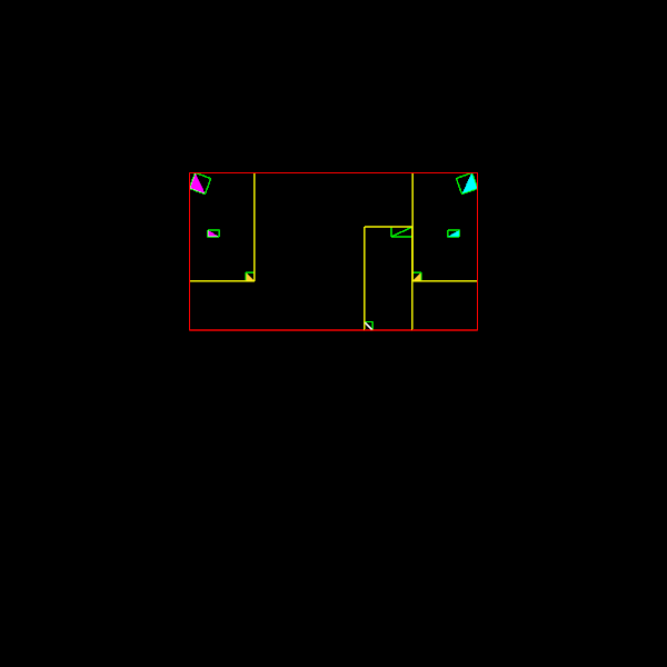
Example Image
We provide an example image of the default fish scene a few frames in to
its animation:
as3_ex.png.
This is not a 'spec,' so you do not necessarily need to get exactly the
same image for the default scene, but it may help to see roughly what to
expect. (Of course, for your own image you should create a new scene!)
One point to note is that the lower level bounding boxes should be axis
aligned relative to the local coordinate frame rather than relative to
screen space, as in
the
lecture example.