| Due: | 2008.08.01 @ 11:59pm |
|---|---|
| TA: | Albert Chae |
Do we need combinational logic, sequential logic, or a combination of the two to implement each of the following:
Describe the effect that a single stuck-at-0 fault (i.e., regardless of what it should be, the signal is always 0) would have for the signals shown below, in the single-cycle datapath (Figure 5.17). Which instructions, if any, will not work correctly? Explain why.
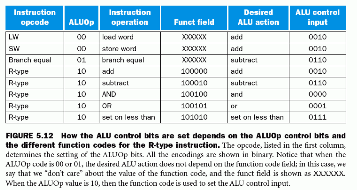
Recall that this datapath only implements the instructions listed in figure 5.12, so these are the only ones you need to analyze for this problem or any other that refers the base single-cycle datapath.Consider each of the following faults separately:
This exercise is similar to Exercise 5.2, but this time consider stuck-at-1 faults (the signal is always 1).
We wish to add the instruction jr (jump register) to the single-cycle datapath (Figure 5.17) described in this chapter. Add any necessary datapaths and control signals to the single-cycle datapath and show the necessary additions to the following table (Figure 5.18).
| Instruction | RegDst | ALUSrc | MemToReg | RegWrite | MemRead | MemWrite | Branch | ALUOp1 | ALUOp0 |
| R-Format | 1 | 0 | 0 | 1 | 0 | 0 | 0 | 1 | 0 |
| lw | 0 | 1 | 1 | 1 | 1 | 0 | 0 | 0 | 0 |
| sw | X | 1 | X | 0 | 0 | 1 | 0 | 0 | 0 |
| beq | X | 0 | X | 0 | 0 | 0 | 1 | 0 | 1 |
(See Figure 5.18 for more explanation)
This question is similar to Exercise 5.8 except that we wish to add the instruction sll (shift left logical), which is described in Section 2.5.
Consider the single-cycle datapath (Figure 5.17). A friend is proposing to modify this single-cycle datapath by eliminating the control signal MemToReg. The multiplexor that has MemtoReg as an input will instead use either the ALUSrc or the MemRead control signal. Will your friend's modification work? Can one of the two signals (MemRead and ALUSrc) substitute for the other? Explain.
Create a directory named 'hw6' containing a README and any additional files needed for your submission. The README should say where to look for each question's solution. While in that directory, run 'submit hw6'. For your included images, make sure to say "yes" when the submit script prompts you about it. Please only submit images in the following formats: PNG, GIF, JPG, and PDF.