no quiz
You type a character, it appears on the screen. You think, that's all there is to it. Well, like everthing else in machine structures, a lot happens under the covers to make it all seem natural.
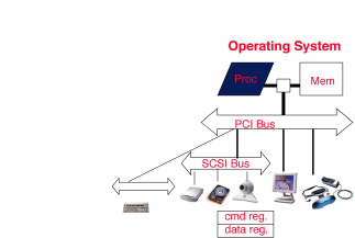
What's needed for input and output? Input comes from and output goes to a device like a mouse (input), a printer (output), or a disk (input or output). Thus there needs to be a way to connect these devices to the computer. There must also be a way to control these devices, respond to them, and transfer data. Transferred data is essentially a sequence of bytes. The transfer takes place over a bus; examples are shown below.
Several aspects of i/o make it more complicated than dealing with memory. First, it's unpredictable: a memory location is always "ready" to be loaded, while a character from an input device might not be. Second, it's relatively slow. Transfer speed for typical devices are listed in the table below.
| device | behavior | partner | data rate (KBytes/sec) |
| keyboard | input | human | 0.01|
| mouse | input | human | 0.02|
| laser printer | output | human | 100.00|
| music output | output | human | 200.00|
| magnetic disk | storage | machine | 10,000.00|
| wireless network | I or O | machine | 10,000.00|
| graphics display | output | human | 30,000.00|
| wired local-area network | I or O | machine | 1,000,000.00
Compare these data rates to that of a 1 GHz microprocessor, which can execute one billion load or store instructions per second, or 4,000,000 KBytes per second.
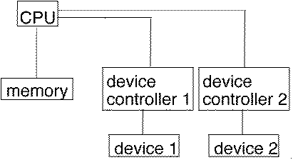
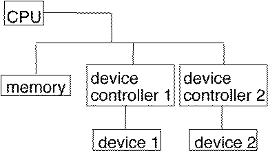
Older computers had special instructions for i/o. In contrast, the MIPS, like most modern machines uses memory-mapped i/o. A portion of the address space is dedicated to communication paths to input or output devices; input is done via a load from an address in this space, and output is done with a store. The two organizations are displayed below.
| special i/o instructions | memory-mapped i/o |
 |
 |
I/O devices have their own internal registers. The processor communicates with them by reading and writing these memory mapped registers. The trick is that the I/O device runs concurrently with the processor. So we need a handshake to keep the two working together properly.
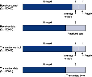
A typical device has a data register and a control register. Each register is represented by a memory location as shown below. The control register contains an "am I ready?" bit that says if it's OK to read or write. The device has write access to this bit; the CPU has read access. To do input, we load from the address that corresponds to the input device's data register after checking the control register (again via load) to see if the device is ready. Output is similar: we load from the address corresponding to the control register, make sure the device is ready, and store into the device's data register.
Programs normally run in user mode. However, accessing device registers directly requires that a program be running in kernel mode (sometimes referred to as "supervisor mode"). The main idea of kernel mode is to keep the operating system from getting trashed by user. For now, we are going to pretend we are part of the kernel and just get the I/O handshake working.
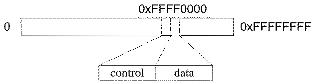
The MARS interpreter simulates a single i/o device, a memory-mapped terminal (keyboard + display). (MARS unfortunately doesn't yet do any of this.) The receiver reads characters from the keyboard, while the transmitter writes characters to the display. Each has a one-word control and data register, accessed by addresses 0xFFFF0000 through 0xFFFF000C as shown below in P&H Figure A.8.1.
One way to do i/o is by polling. The processor reads from the control register in a loop, waiting for the corresponding device to set its "ready" bit. The processor then loads from (input) or stores into (output) the associated data register. This load or store unsets the ready bit temporarily until the i/o operation is completed. Code fragments to read and write a character using polling appear below.
| character input into $v0 ______________________ | output of character in $a0_________________ |
lui $t0,0xffff #ffff0000 waitloop: lw $t1,0($t0) #control andi $t1,$t1,0x0001 beq $t1,$0,waitloop lw $v0,4($t0) #data |
lui $t0,0xffff #ffff0000 waitloop: lw $t1,8($t0) #control andi $t1,$t1,0x0001 beq $t1,$0,waitloop sw $a0,12($t0) #data |
The ~cs61cl/code/char.s gets a single character from the keyboard and puts it to the display. Study the code for the getc and putc routines and make sure you understand why they do what they do.
IO in MARS is still a little new. The version of MARS that you need to run is a ~cs61cl/bin/mars-3.5/MarsIO.jar. Run this, open and assemble char.s. Select Tools->Keyboard and Display MMIO Simulator. Click Connect to MIPS. In the main MARS window, select the 0xFFF000 (MMIO) portion of the data segment. This is the memory mapped IO area. Notice the four words that are the control registers described above. Click Reset in MMIO simulator.
Which ready bit goes on? It needs be on before you can successfully perform I/O. (This is a clubsy part of the MARS I/O simulator.)
Single step the code. See how it is waiting, polling the rcv ready bit? Type a key into the keyboard window of the MMIO tool? See it show up in the data register and the ready bit go on.
Now if you continue single stepping you see it find the tx ready is on and it will display the character.
The help button on the MMIO tool gives more of the specifics for MARS.
Run your echo.s at max with a 100 instruction transmitter delay. See the lag when you type. Still the chracters get there because the reading from the keyboard is synched with the writing to the display.
In echo, comment out the three lines of putc that wait for the display to be ready before writing to it. Run this at max with the same transmit delay. Now what happens when you type at it quickly?
Copy over ~cs61cl/code/kecho.s and study what you find there. The getc and putc routines are in the kernel segment, while main is in the user text segment. Assemble it in MARS and look at the addresses for the instructions.
Why must we use a JALR to call into the kernel segment?
Uncheck DAD in the MMIO tool to run this. Single step through and see how the program enters and leaves the kernel as it performs I/O.
As you might guess, it's generally a waste of CPU resources to have a program constantly querying an i/o device to see if it's ready. It's like checking the clock every few minutes to see whether it's time to get out of bed. Another way to do input and output is to rely on interrupts. An interrupt is like an unplanned procedure call that's invoked only when the i/o device is ready. Setting this up requires enabling the device to interrupt.
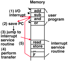
When an interrupt-enabled device becomes ready, execution is interrupted by the hardware, kernel mode is entered, and control is transferred to a special location in kernel space. The code at that address does whatever needs to happen to service the interrupt—either making it not ready or disabling further interrupts—then returns control to the formerly executing program (leaving kernel mode if appropriate). There should be no other side effects noticeable to the interrupted program. Control flow is illustrated in the diagram below. An i/o interrupt is thus asynchronous with respect to instruction execution; it can happen in between any pair of instructions.
MIPS interrupts are handled through coprocessor 0. (Recall that we discussed coprocessors earlier in the context of floating-point computation. The floating-point co-processor is coprocessor 1.) Coprocessor 0 provides several registers that a programmer may use to enable interrupts and access status information such as the address of the interrupted instruction.
Enabling keyboard and display interrupts on the MIPS is a two-step process. First, we turn on some bits in the coprocessor 0 Status register. Then we turn on the "interrupt enable" bit in the control word. This may cause an interrupt right away if the device is ready.
When an interrupt happens, control is immediately transferred to location 0x80000180. (Some computers have different entry points for the various kinds of interrupts. MIPS provides just one entry point, but provides enough information to figure out what device caused the interrupt.)
The first thing that happens in the interrupt-handling code is the saving of registers that the code will use. These include the $t registers and $at, any of which may be in use in the interrupted instruction. The choreography of doing this is sometimes complex, so by convention registers $k0 and $k1 are reserved for use by the operating system (which includes interrupt handlers).
Handler code goes on to determine what caused the interrupt, and to act accordingly. As noted earlier, loading a character from the receiver (keyboard) data register or storing a character into the transmitter (display) data register makes the device not ready, removing the possibility of an immediate subsequent interrupt on that device.
Processing both of input and of output involves the use of a buffer of characters. Webster defines "buffer" as "a device used as a cushion against the shock of fluctuations in business or financial activity." Here, we're worrying about the "shock" of connecting a fast producer of characters to a slow consumer of characters. Our buffers—one for input and one for output—are queues of characters. A print function adds characters to the end of the queue; the output interrupt handler removes and prints the character at the head of the queue.
An efficient implementation of this queue uses a circular array. A "head" variable contains the index of the first character in the queue unless the queue is empty. A "tail" variable contains the index of the first empty space in the queue. In an empty queue, head == tail. In a full queue, head == (tail+1)%size, where size is the number of elements in the array.
Copy over ~cs61cl/code/echoint.s and load it into MARS. The user node is no longer doing the work here. It make a kernel call to enable_rxint. In the MIPS, coprocessor 0 is the system coprocessor. It contains a status register that includes critical system info such as whether interupts are enabled or disabled and when one occurs what is its cause. Here we disable interrupts before manipulating the I/O device. We then modify the rcv control register to set the bit that will tell it to signal interrupts to the processor.
Set the instruction rate to something interactive, bring up the MMIO tool, get rid of DAD, and turn down the Delay length. Step through the code to see this call get performed to enable interrupts. If you let it run you will see that the user code just loop.
Pause the simulation and set a breakpoint at interp. Notice that this is a very special routine. It resides at a particular hardware address - 0x80000180. When an interrupt occurs, the process stops what it is doing, saves the PC in the EPC regsiter and sets the PC to this address. All the registers belong to the interrupted code, so we can't touch any of them. Here we save everything that we might need.
Normally, we would handle whatever interrupts have occured, access I/O devices and put the data into buffers. Here we have programmed the interrupt handler to do exactly one thing - echo the key to the output.
Step through this and see how it works. Try a few more keys. Get rid of the breakpoint and see that this interrupt driven I/O really does work.
A buffer of 16 characters is used for input characters. If this buffer fills up without being read, subsequent characters are discarded. (This shouldn't happen with the current program setup.) The input interrupt handler checks for this, and tallies the number of dropped characters.
Experiment with other buffer sizes to find the largest buffer size that still results in dropped characters.