This is an individual project; your work must be your own. (The "no code" rule described in the "General Information" document applies here.) Submit a solution by 11:59pm on Wednesday, Oct 1. Your submission directory, called proj1, should include a file named assembler.c plus all other source files necessary to build an executable version of your program. It must include a file named Makefile such that running the make program will produce an executable file named proj1.
You have three grace days to apply toward late project submissions over the entire term. Don't use them all at once. Start early. When you get confused, ask for clarification. Get easy pieces working and then move forward.
As a first step, this week you will need to ask one question and answer one question about the project in a UC-WISE discussion step for homework for the weekend of September 20. (No exceptions.)
You are to write an assembler that translates a CAL16 assembly language program into machine language, and in addition produces information about symbols used in the program.
You will shortly be introduced to the machine architecture for the MIPS computer, a real-life computer that grew out of David Patterson's RISC project here at Berkeley and John Hennesey's MIPS project at Stanford. (The Sun SPARC architecture is even closer to the Berkeley RISC.) All the things a computer can do are defined by its instruction set, which includes instructions that, among other things, do arithmetic, make comparisons, and control the execution flow of a program. The MIPS instruction set architecture (ISA) also includes registers, special machine storage in which operands to machine instructions are held. MIPS machine instructions are represented in binary as 32-bit words. As you have seen, binary values are very painful for humans to work with (you can't even print them without translating them to characters first). An assembly language is essentially a human-readable version of a machine language. It represents each instruction in an English-like form, and an assembler "assembles" each of the parts of assembly language program into its machine language counterpart. It is essentially a 1-1 translation of a textual form of instructions and static data into its binary form.
As a starting point, we will consider a machine architecture designed especially for CS 61CL, namely the CAL16. It's much simpler than the MIPS. Each step of the process that turns assembly language text into a runnable program is thus simpler and more accessible than its counterpart on a real-life computer. In this project, you'll implement the first step in the process, namely the translation of CAL16 assembly language to machine language format. You don't need to worry about what each instruction does at this stage; we'll spend lots of time later on that. For now, we're just going to translate the human-readable format to an ASCII version of the corresponding machine language.
An important aspect of an assembler is its handling of labels. Keeping track of the value of each label involves storing them in a symbol table; you've had practice with various parts of this process in earlier lab exercises. In particular, you must correctly handle forward references, uses of a label before it's defined. A second part of this project is output of the symbol table.
A CAL16 program is stored in a file whose name ends in ".c16". Each line of a CAL16 assembly language program may contain the following:
Each label is a letter followed by a series of "symbol characters", that is, letters, digits, or the underscore ('_') character, followed by a colon (":").
Each instruction is terminated by a ';', with no whitespace separating the last operand from the ';'.
Whitespace may but need not follow the ':' in a label or the ';' terminating an instruction.
Each comment starts with the pound-sign character ('#') and continues to the end of the line.
The rules above define all legal lines.
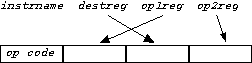
Each instruction consists of an instruction name (opcode) followed by operands; the number and format of the operands depend on the instruction. There is a special "pseudo instruction" .data that permits the declaration of static variables. The allowable instructions are the following.
	and   destreg  op1reg  op2reg
	or    destreg  op1reg  op2reg
	xnor  destreg  op1reg  op2reg
	add   destreg  op1reg  op2reg

	addi  destreg  opreg  signedint4
	rotr  destreg  opreg  unsignedint4

	ld    destreg  signedint4(opreg)
	st    destreg  signedint4(opreg)
	jr    destreg  signedint4(opreg)

	bneg  destreg  labelsymbol
	bz    destreg  labelsymbol
	lhi   destreg  labelsymbol
	llo   destreg  labelsymbol
	lhi   destreg  unsignedint16
	llo   destreg  unsignedint16

	jmp   labelsymbol

	.data signedint
Operands are preceded by whitespace and separated by whitespace. (The second operand for the ld, st, and jr instructions, even though it specifies two pieces of information, contains no whitespace.)
Each reg in the instructions above has the format $n, where n is one of {0, 1, ..., 15}. Each signedint4 is one of {–8, –7, ..., 7}, and each unsignedint4 is one of {0, 1, ..., 15}. A labelsymbol is a label without the terminating colon. Finally, signedint16 stands for a 16-bit signed integer and unsignedint16 a 16-bit unsigned integer respectively.
An example assembly language program follows showing the various types of instructions, along with labels and comments. You are not expected to understand exactly what it does. You will be assembling it and other test cases into valid machine code.
# Here is a sample program.
main:				# function main
	and	$3  $0  $0;	# clear r3
	lhi	$3  counter;	# get upper address of counter
	rotr	$3  $3  8;	# move it to MSB
	llo	$3  counter;	# lower portion in LSB
	ld	$4  0($3);	# load the initial value into r4
loop:	bz	$4  done;
	or	$2  $3  $3;	# move to arg register
	jr	$1  2($3);	#
	addi	$3  $3 -1;	# decrement the counter
	jmp	loop;
done:
	jmp	done;		# stuck here

counter:.data	61;
dummy:
	jr	$0  2($1);	# just return
	jmp	foo;
Each assembly language instruction in a file is to be translated into a 16-bit machine instruction. For the .data pseudo-instruction, the translation is immediate: the binary representation of its argument. Each other instruction has a four-bit op code (short for "operation code"), displayed in the table below, followed by operand fields that fill out the 16-bit word. The op code is the most significant 4 bits. You can think of it as the leftmost hex digit.
| instruction name | op code | instruction name | op code | |
| and | 0 | llo,lhi | 8 | |
| or | 1 | UNUSED | 9 | |
| xnor | 2 | bneg | A | |
| add | 3 | bz | B | |
| addi | 4 | jr | C | |
| rotr | 5 | UNUSED | D | |
| ld | 6 | UNUSED | E | |
| st | 7 | jmp | F |
A couple of notes: lhi and lho are both the "load immediate" instruction and have op code 8. They differ in how the assembler processes their argument, as discussed below. There is no instruction with op code 9, D, or E. (Those are reserved for future use.)
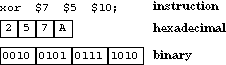
The and, or, xnor, and add instructions each have three register operands. Since registers are numbered from 0 to 15, each register operand can be represented in four bits. The four-bit op code together with the twelve bits for register operands form the 16-bit machine instruction. You can think of it as four hex digits: the first is the opcode and the rest are register specifiers. A slight wrinkle here is that the operands appear in a different sequence from how they appear in the assembly language instruction, as shown below.
| R-R Format | Examples |
|
|
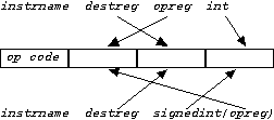
The second type of instruction treats one of the operand fields as an constant immediate value, rather than a register specifier. ("Immediate" in this context means "stored in the instruction itself" rather than accessible indirectly in a register.) Two of these instructions, addi and rotr, take three separate arguments: two registers and a small integer (small enough to fit in four bits) as arguments. The immediate operand in the addi instruction is signed; its counterpart in the rotr instruction is unsigned. In three others, ld, st, and jr, the second and third arguments are combined in the form
signedint(opreg)
The machine language representation of these instructions, however, are the same, with the destination register and the operand register switched as in instructions already discussed.
| Reg-Imm Format | examples | hexadecimal representation | binary representation |
 |
ld $12 -2($1) |
61CE |
0110 0001 1100 1110 |
The remaining instructions all involve handling of labels. Each instruction takes up two bytes (16 bits) of memory. Thus the first instruction is at address 0, the second at address 2, the third at address 4, and so on. The value of a given label, then, is the address of the instruction it labels. As in earlier lab exercises, you'll need to maintain a symbol table that keeps track of the definition and uses of each label.
A third class of instructions are "load immediates" and branches. They combine the least significant 8 bits into an immediate value. "Load immediate" is often used for constructing a literal value in a register. In many cases, we will want to build a full 16-bit value, but there's not enough room in the 16-bit instruction to do this; four bits are used for the opcode and four for the destination register. Thus, we need to construct the literal eight bits at a time. The two assembly forms, llo and lhi, translate into the same opcode, but the former is used to insert the lower eight bits of the constant value (its rightmost eight bits) and the latter the upper eight bits (its leftmost eight bits). When the literal is a label, this would be the lower and upper portions of the address associated with the label.
Here's an example. Suppose that the symbol count labels the instruction at address 52A4. Then the llo and lhi instructions in the table below are translated as indicated.
| instruction | translation |
| llo $7 count | 87A4 |
| lhi $7 count | 8752 |
Branches are handled differently. Their 8-bit field is the relative distance in 16-bit words from the branch instruction to the target. (This is the same as the number of instructions from the branch to the target.) It must be in the range of –128 to 127. It is a signed value, as it is used for branching both backwards and forwards. Three examples appear in the table below.
| program segment | translation |
early: ld $12 -2($1) bz $7 late infloop:bneg $14 infloop addi $15 $11 -3 late: bz $5 early |
61CE B703 AE00 4BFD B5FC |
Finally, the jmp instruction combines all three fields into a 12-bit value, which is most of the word address—bits 1-12, counting from the right—associated with the label. If the symbol done labels the instruction at address 743A (0111 0100 0011 1010 in binary), the instruction jmp done would be translated as follows:
| binary | hexadecimal |
| 1111 1010 0001 1101 | FA1D |
Your program will be run with the command form
proj1 name.c16
where name is a nonempty sequence of non-whitespace characters. (Running the make program would have produced the executable proj1.) It will produce three text files: name.o, which will contain an ASCII version of the corresponding machine language. name.syms, which will contain an ASCII representation of the symbol table, and name.lst, which is a listing that interleaves the lines of input with the resulting machine code. This is what you will use most for debugging.
For example, running your program on a file named test.c16 should produce files named test.o, test.syms, and test.lst.
The format of the ".c16" file is described above. If the command-line argument is improperly specified or you encounter any illegal instructions, print an explanatory message to stderr and terminate the program by calling exit(1). Note: a reference to an undefined label should not be considered as an error in this context.
Each line in the ".o" file will consist of the ASCII representation of four hexadecimal digits. An example assembly language segment and its representation in the ".o" file appears below.
| assembly language | corresponding ".o" lines |
ld $12 -2($1); addi $15 $11 -3; rotr $7 $3 14; jr $8 6($9); |
61CE 4BFD 537E C986 |
Each line in the ".syms" file will contain information about one of the lines in the symbol table, in the following format:
labelsymbol defined? value type1 refaddress1 type2 refaddress2 ...
where the fields in the line are as follows:
The value of an undefined symbol is FFFF.
There may be any number of type-refaddress pairs. For example, an unreferenced label will have none. The order of type-refaddress pairs in the output is unspecified, as is the order of lines in the output.
All addresses are four hexadecimal ASCII digits. Fields in the output line are separated by whitespace.
The sample assembly language program given above would thus yield a ".syms" file with six lines:
	main	y 0000
	loop	y 000A jmp 0012
	done	y 0014 b 000A jmp 0014
	counter	y 0016 lhi 0002 llo 0006
	dummy	y 0018
	foo	n FFFF jmp 001A
The order of lines in the ".syms" file and of references within a line is not specified.
Your listing should appear as follows. It shows the line number and text for each line in the program. Each line that contains an instruction is followed by an indented line that has the location of that instruction and the machine code that would be placed at that address. Whitespace separates all relevant components of each line.
   0	# Here is a sample program.
   1	main:				# function main
   2		and	$3  $0  $0;	# clear r3
	   0	0030
   3		lhi	$3  counter;	# get upper address of counter
	   2	8300
   4		rotr	$3  $3  8;	# move it to MSB
	   4	5338
   5		llo	$3  counter;	# lower portion in LSB
	   6	8316
   6		ld	$4  0($3);	# load the initial value into r4
	   8	6340
   7	loop:	bz	$4  done;
	   a	b405
   8		or	$2  $3  $3;	# move to arg register
	   c	1323
   9		jr	$1  2($3);	#
	   e	c312
  10		addi	$3  $3 -1;	# decrement the counter
	  10	433f
  11		jmp	loop;
	  12	f005
  12	done:
  13		jmp	done;		# stuck here
	  14	f00a
  14
  15	counter:.data	61;
	  16	003d
  16	dummy:
  17		jr	$0  2($1);	# just return
	  18	c102
  18		jmp	foo;
	  1a	ffff
Your assembler will read a text file containing assembly language instructions. It will go through the file line by line. It will discard the comments, locate all the label declarations, and parse the instructions and data statements. It will translate each instruction into the equivalent binary machine code representation. This will involve translating the textual representation of integers into binary values, but also translating each label into the memory address it represents. How do you know what address is associated with a label? You have to construct a representation of all the instructions and data. Most assemblers run in two passes, first parsing all the instructions, building a skeleton of each, and finding all the label declarations and uses, then going through and resolving all the labels to their values.
How do you tackle a hard problem? Divide and conquer. Don't try to write your project as a huge monolith of code. Break it into pieces that do simple things well. Think about what you have in hand already. You have tools that read files and build data structures containing the lines as strings. You have built scanners that run through strings and pull out comments or labels or words. You have built repositories that collect a bunch of symbols and information about them. You can insert new ones and lookup old ones. You know how to build arrays of things and lists of things, and the things can be anything—chars, ints, structs, arrays, lists. And you have translated from strings to numbers. So you have all the pieces. Now we want to orchestrate these abstractions to parse assembly language files and produce machine language files.
We hope that your previous programming experience has taught you to develop your program in manageable pieces, and to add functionality only when you're sure that you're building on a foundation of correct code. We encourage you to make use of code you encountered or wrote earlier in this course.
Some suggested approaches:
The following summarizes the binary machine format. It has
sixteen instructions, each a 16-bit word. The word can be viewed as
four 4-bit fields. Some instructions combine the last two into an
8-bit field, one combines all three into a 12-bit field. The mnemonic
is the assembly language version of the opcode. Later we will
explance the Register-Transfer level semantics in this table. For
now we are just concerned with translating the human-readable assembly
language into a representation of the machine-readable, binary format.
| OP | Q2 |
Q1 |
Q0 |
MNE | Semantics | ||
| 0 | a | d | b | and | R[d] := R[a] & R[b] | PC := PC+2 | |
| 1 | a | d | b | or | R[d] := R[a] | R[b] | PC := PC+2 | |
| 2 | a | d | b | xnor | R[d] := ~(R[a] ^ R[b]) | PC := PC+2 | |
| 3 | a | d | b | add | R[d] := R[a] + R[b] | PC := PC+2 | |
| 4 | a | d | off4 | addi | R[d] := R[a] + Sx(off4) | PC := PC+2 | |
| 5 | a | d | off4 | rotr | R[d] := R[a] rot off4 | PC := PC+2 | |
| 6 | a | d | off4 | ld | R[d] := Mem(R[a] + Sx(off4)) | PC := PC+2 | |
| 7 | a | d | off4 | st | Mem(R[a] + Sx(off4)) := R[d] | PC := PC+2 | |
| 8 | a | off8 |
ldi | R[a] := 0||off8 | PC := PC+2 | ||
| 9 | |||||||
| A | a | off8 |
bneg | PC := (R[a] < 0) ? PC+Sx(off8) : PC+2 | |||
| B | a | off8 |
bz | PC := (R[a] == 0) ? PC+Sx(off8) : PC+2 | |||
| C | a | d | off4 | jr | R[d] := PC | PC := R[a]+Sx(off4) | |
| D | |||||||
| E | |||||||
| F | off12 |
jmp | |
PC := (PC & 0xF000) | off12 | |||
R is a 16-element array of registers. PC is the program counter, the address of the currently executing instruction. Mem is the memory array, one element per byte. Sx is a sign-extending function. Given a four-bit signed value, it returns the equivalent 16-bit value.
Register $0 is assumed always to contain 0. It is thus read-only.
An attempt to load $0 from memory or from a computation has no effect.