Touchscreen Lab 2: Resistive Touchscreens
EECS 16A: Designing Information Devices and Systems I, Spring 2015
Name 1:
Login: ee16a-
Name 2:
Login: ee16a-
Instructions
- Complete this lab by filling in all of the required sections, marked with
"YOUR CODE HERE"or"YOUR COMMENTS HERE".
- When you finish notify your GSI to get get checked off for this lab. Be ready to answer a few questions to show your understanding of each section.
- Labs will be graded based on completion for teams of 2 students
Introduction
In the next two labs you will be introduced to two fundamental properties of circuits, resistance and capacitance, by actually building the touchscreens introduced in lecture! This week we will use the soldering skills we learned in Week 1 to make a touchscreen entirely out of resistors and write Arduino code to test the touchscreen. Next week we will switch gears and build a capacitive touch sensor, which will give us a better understanding of how modern touchscreens such as those found in cellphones, tablets, gaming devices, etc. are implemented.
Resistors
The resistor is one of the most basic circuit elements, and you will become very familiar with them during this lab. Resistance ($R$) is determined by the following property:
$$R=\frac{\ell}{σA} = \frac{ρ\ell}{A}$$
The values of σ and ρ correspond to the conductivity and resistivity of the material respectively. The current-voltage relationship of a resistor is governed by Ohm's law:
$$v = iR$$
According to Ohm’s Law, the current flowing through a resistor is directly proportional to the voltage across it.
Touchscreen Theory
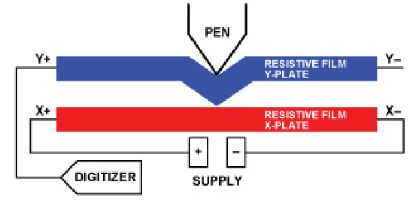
As explained in Lecture 11, the basic principle behind a touchscreen involves sensing changes in resistance corresponding to a user's touch input as shown below. Resistive touchscreens are comprised of two plates,and applying pressure causes the plate to touch and create a short circuit.
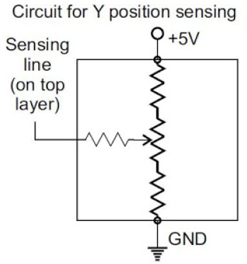
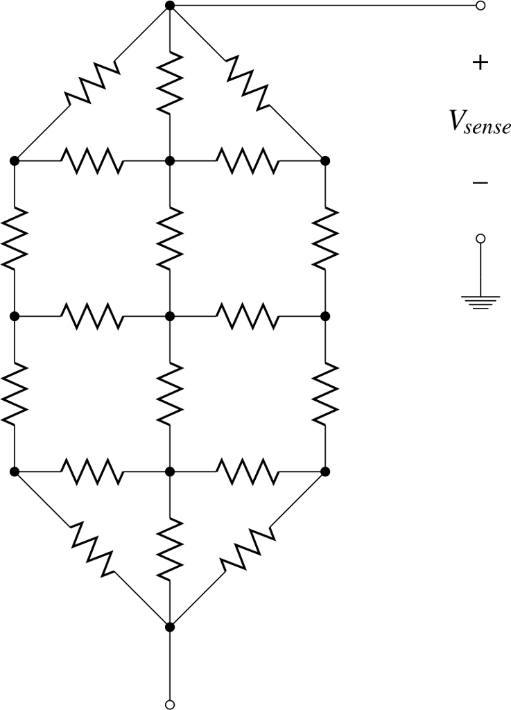
The change in resistance is converted to a change in voltage using the voltage divider circuit introduced in lecture:
The diagram above shows that we must apply a voltage across one set of resistors, while the other is used to read the voltage at a particular point. By applying KCL or KVL to solve the above circuit, we can determine the following relationships for touching a point along one axis of the circuit, where the "height" and width" correspond to the number of resistors along an axis:
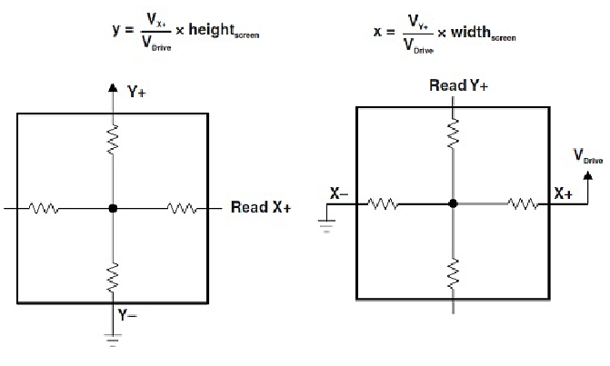
As shown above we can only apply voltage across one axis (drive one axis) at a time, while sensing across the other. It is also important to note that this method requires one wire to be disconnected. In this lab we will begin by manually testing voltages using the multimeter, and afterwards use the Arduino to rapidly switch the drive and sense axes to get "real time" measurements of position along the X and Y axes. The figures below show a schematic of the actual circuit we will assemble to create a 3x3 resistive touchscreen.
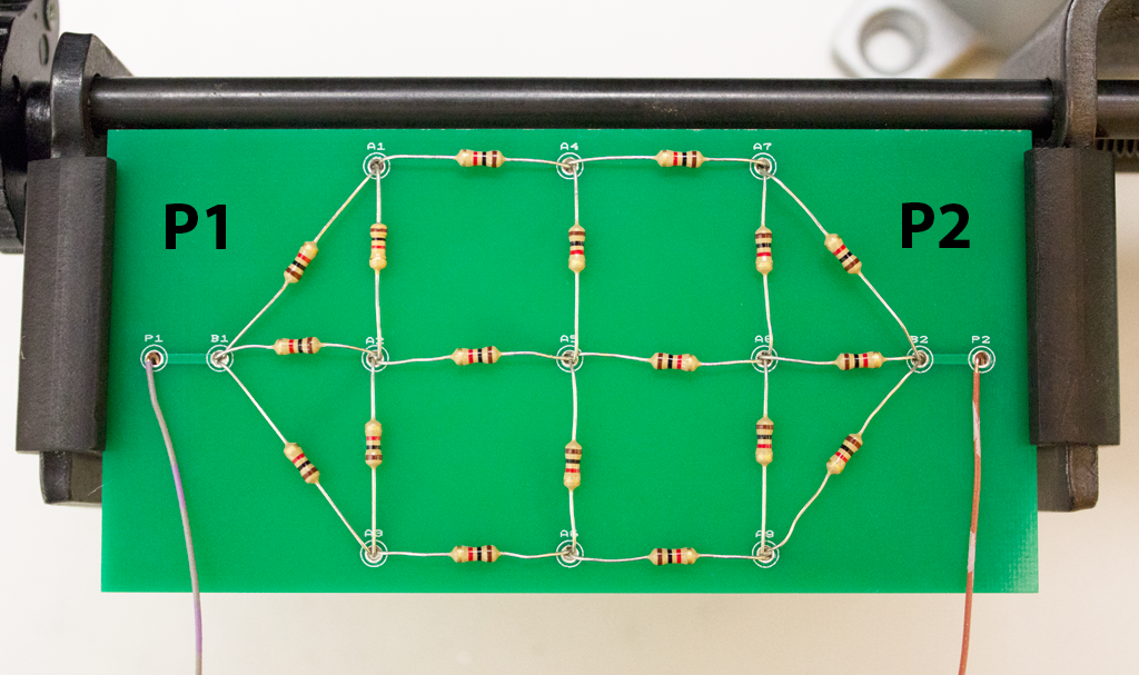
Bottom mesh circuit diagram (PCB)
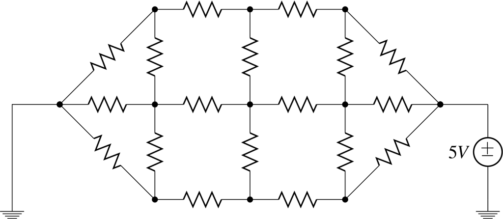
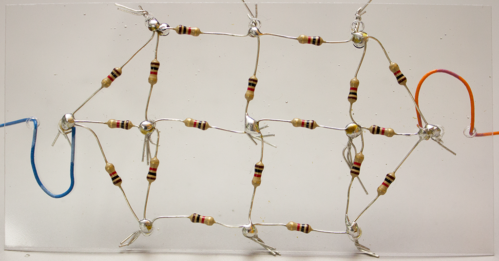
Top mesh circuit diagram (plastic)
Task 1: Touchscreen Construction
We will be building a basic 3x3 touchscreen, providing 9 total contact points. The resistive touchscreens have two layers or ‘meshes’ of resistors, which we will label Top and Bottom accordingly. The Top mesh (clear plastic) has been provided for you; you will begin by assembling the bottom mesh, and then complete the touchscreen by attaching the top mesh and foam separators.
Task 1a: Assemble the bottom mesh
Materials
- 1x PCB
- 18x 1$k\Omega$ resistors
- 2x wires
- Solder
Using the Top mesh as a guide (ignore the foam blocks for now), solder the 1K$\Omega$ resistors on the blank PCB provided. This may take anywhere between 20 minutes and 1 hour, just be patient and do not rush! Your goal is to produce a PCB like the one below:
Helpful tips:
- Use the Vice-Grip to hold your PCB as shown in the image.
- Bend the legs of the resistors and place them in the correct holes before soldering the joints (remember, resistors have no polarity, so don't worry about their orientation).
- Double check that your resistors are laid out properly before soldering
- Center the ceramic part of the resistor between the holes on the PCB or else establishing a point of contact between the two meshes may be difficult.
- Make each joint as flush to the PCB as possible.
Task 1b: Adding the Top Mesh
Materials
- 8x 1cm x 1cm foam pieces
- 1x top mesh
Hot glue
Once you have finished soldering the Bottom mesh, the next step is to attach it to the top mesh and add a flexible separator between the two. The pre-built top mesh has the same pattern as the bottom:
Position the Bottom mesh with its lead wires going East-West.
- Attach the adhesive side of one piece of foam to the non-adhesive side of the other to create a stack of 2 foam pieces.
- Use hot glue to attach the remaining non-adhesive side to the PCB in the center of each square of resistors.
- Orient the Top mesh on top of the Bottom mesh with its lead wires going North-South. The resistors on the top mesh should be facing down towards the PCB.
- Use the adhesive on the foam to stick the plastic top mesh in place with the large solder joints oriented toward the PCB.
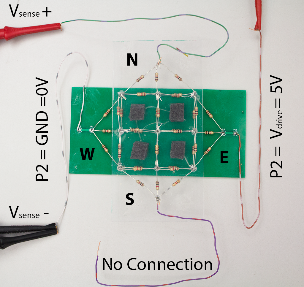
The resulting sandwich should resemble a ‘+’ symbol:
Task 2: Testing the Circuit
Materials
- Assembled touchscreen
- 4x test leads
- Multimeter
- Power supply
It’s time to test our touchscreen! First, to stay organized it is important that we define an origin to refer to. Orient your screen so that the solder-joint labeled A1 on the PCB is at the top-left; this will be our origin.
Given this orientation and origin, in order to sense a horizontal position which mesh (top / bottom) will be driven with a voltage source, and which mesh will we measure the voltage across?
For sensing a vertical position, which mesh (top / bottom) will be driven with a voltage source, and which mesh will we measure the voltage across?
Test sensing with the top mesh
- Use the Power Supply to supply 5V to the Bottom mesh; GND to the West (P1) lead and 5V to the East (P2) lead.
- Hookup the leads of the Top Mesh to the Multimeter; V+ to the North lead and V- to GND (West/P1). The South lead has no connection.
- Push the two layers together at a particular point and record the output voltage of the Multimeter to 2 decimal places in the "Top Mesh" column of the chart below.
Test sensing with the bottom mesh
- Use the Power Supply to supply 5V to the Top mesh; GND to the South lead and 5V to the North lead.
- Hookup one lead of the Bottom Mesh to the Multimeter and the other to GND (V+ to the West/P1 lead and V- to GND/South). The East (P2) lead has no connection.
- Push the two layers together at a particular point and record the output of the Multimeter in the "Bottom Mesh" column of the chart below.
Complete the table below with the voltages measured at each joint.
| Joint | Top Mesh (V) | Bottom Mesh (V) |
| A1 | ||
| A2 | ||
| A3 | ||
| A4 | ||
| A5 | ||
| A6 | ||
| A7 | ||
| A8 | ||
| A9 |
Task 3: Touchscreen Processing
Ultimately, we want to be able to determine the precise location of our finger on the screen. While reading voltages off of the multimeter is good for testing purposes, it is slow and not practical for actual usage. We will now use the Arduino to automate this process.
Arduino Syntax
Writing code for the Arduino requires using a different programming language more similar to C or C++ than Python. The major conceptual differences are outlined below:
- Arduino code has to be compiled from the source code you write into a format that can be loaded onto the chip. While some python implementations do this behind the scenes, unlike Python you can't open up an interpreter style interface and test commands.
- The Arduino language requires explicit specification of types. When declaring a variable, the compiler will require you to specify a type (
intfor integers,floatfor floating point values, etc). - The Arduino language does not use white space to separate functions or statements.
- All lines other than function declarations end with a semicolon
;. - The beginning of a function is marked by a an open brace (
{) and the end of a function is marked by a close brace (}).
- All lines other than function declarations end with a semicolon
This cursory explanation should be all you need to complete this lab, more detailed language documentation can be found on the Arduino website.
Begin by connecting your Arduino to the computer via USB and connecting the touchscreen wires to the following ports on the Arduino:
| Touchscreen Wire | Arduino Pin |
| W (P1) | A0 |
| E (P2) | A1 |
| N | A2 |
| S | A3 |
Next, load the file EE16A_Touchscreen_Week2.ino in the Arduino IDE. Take a few minutes to walk through the code with your partner(s). Try to understand the purpose of each function. You can ignore the implementation of set_vdrive().
Fill in the two missing lines (39 & 40) marked YOUR CODE HERE to convert voltage values x_voltage and y_voltage to the corresponding X or Y positions.
Test your code by making sure that the Arduino prints the correct location (A1-9) when you press that location on your touchscreen.
- Check to make sure you have the correct serial port connected (make sure to select the value that is NOT
COM1) - Open the serial monitor by clicking the magnifying glass icon on the top right (you need to close and reopen the serial monitor each time you upload code):
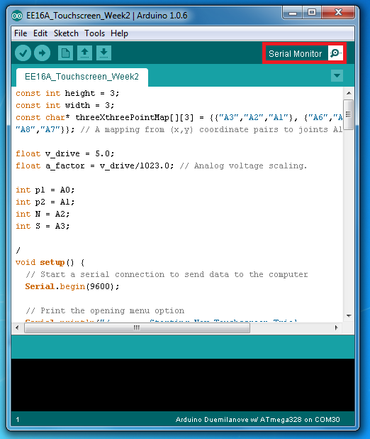
- Type
nat the prompt to keep the default value ofv_drive. - Press each point on the touchscreen and make sure it is correctly printed on the screen.
Once you get your code working with the default v_drive, try different values for v_drive.
Congratulations, you have built a functioning touchscreen!