Programming an LCD
I Introduction
This document details how I programmed a C167 to
control a dot matrix LCD for UC Berkeley's EE40 robot competition.
II The LCD
The LCD is a HD44780-based Character-LCD. It has 2
rows of 16 characters. The LCD can display English letters, Arabic
numbers, or even characters of your own design.
III Interfacing the LCD
The first step in getting the LCD to work is
figuring out which pins are where.
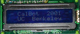
The above is a shot of the LCD
as it was finally mounted on the CalBot I built in 2001. The data bus wire
wraps are visible on top.
The LCDs interface consists of 11 bits.
8 of these carry data (DB0-DB7), the remaining 3 are control bits (RS, R/W,
E).
The RS (data/instruction select) bit tells the LCD whether we are
going to send an instruction or a piece of data.
The R/W (read/write) bit
tells the LCD whether we wish to read from or to write to RAM.
The E
(enable) bit tells the LCD when it should read the data lines.
All of
these bits need to be connected to different pins on the board. I decided
to use port 3 because I wanted port 2 available for controlling the LED's, and
the rest of the ports didn't have 11 bits. Having the LCD on just one port
makes life pretty easy.
I connected RS to P3_0, R/W to P3_1, DB0-7 to
P3_2 - P3_9, and E to P3_13.
Finally, the LCD must connected to +5V and
ground. I got a 5 volt regulator for this purpose.
IV Programming the LCD
Part 1 - Instructions
Now that the LCD is attached to port 3, we can
start telling it what to display. We will use two different functions: one
for giving instructions, and one for giving data.
Let's first look at a
data
sheet for the LCD. Page 5 gives the instructions that the LCD
understands.
Before we send the LCD characters, we must initialize it.
The first initialization command is "Function Set".
DB7 and DB6 are
zero, DB5 is 1. DB4 indicates data length (in our case "1" to indicate 6
bits), DB3 selects number of display lines ("1" for 2 display lines), DB2
selects the display font (necessarily "0"), and DB1 and DB0 don't matter (call
them "0").
It is easier to think about the hexadecimal equivalent than
trying to keep track of all of the ones and zeros. It is important at this
point to understand how our board expresses ports. Port 3 is a 16 bit
port, meaning that there are 16 pins represented by 16 bits (P3_15 - P3_0).
The port can also be addressed as a 2 byte hexadecimal word: 0x0000 -
0xFFFF. This provides a convenient way to either examine or set the
contents of the port in one line of code. Finally, it is important to note
that the highest pin is the leftmost bit. For example, P3 = 0x0010 sets
P3_4 to 1 and everything else to 0, _not_ P3_8 to 1.
So what hex command
do we want to send to board? Remembering the above, we decided above we
wanted to say
0b00111000
However, we wired RS and R/W to be the
"lowest" (rightmost) pins, so we have to append their values to the right hand
side. Doing so gives us:
0b0011100000
Now we break it up
into sets of four (from the right) and add up bits:
0b00 1110 0000
0x0
E 0
== 0xE0
So, we want to write 0xE0
to the LCD.
Of course, 0xE0 isn't the only thing we'll be writing to the
LCD. It would be useful, therefore, to write a function that takes data to
be written as the argument and does the actual writing itself.
Take a
good look at the "Write Operation" timing chart on page 4. Go ahead - I'll
wait. Get it?... it took me and my partner two weeks to
decipher.
Here's what it says: First we set RS high or low
(data/instruction) and R/W low (write). Then we wait 140 ns. Then we
set E high. Then we set our data pins. Then we wait 80 ns.
Then we "flip" E from high to low. Then we wait 10 ns and move on
with our lives.
Let's do that. To send an instruction, we want to
set RS and R/W both low and wait.
P3 =
0x00;
ourdelay(50);
Then we set E high and
wait.
P3 = 0x2000;
ourdelay(50);
Then we set our data
pins by OR'ing the port with our data.
P3 = P3 |
0xE0;
ourdelay(50);
Finally, we flip E and wait.
P3 =
P3 & 0xDFFF;
ourdelay(50);
There are a few more
initialization commands to give. We need to set the entry mode; I set my
LCD to increment and not shift. I also give the "Display ON/OFF Control"
command to decided whether or not to have a cursor. I use the cursor when
developing code for the LCD; it comes in very handy when you miscount and are
wondering where the cursor is. I turn it off when the LCD code is finished
and I'm showing off to my friends. Finally, I clear the display. It
is worth noting that this command takes much longer than most. You must
make sure you wait long enough after clearing the display, or both you and the
LCD will end up very confused.
Part 2 - Data
Now that are our LCD is initialized and ready, let's write
something!
First we'll have to look at the characters the LCD
knows:
Our first character is a dash ("-"). Scanning the table
above, we see that there's a dash in the second column, third from bottom:
0b00101101 = 0x2D. Then we'll need a space, 0x20, and a "C", 0x43,
and so on.
These hexadecimal values are what we want to send on the data
lines. Because we are writing data to the LCD, we know RS will be 0 and
R/W will be 1. You can write a function that will take the hex value we
want to write as an argument and deal with the other bits itself.
V Tips and Tricks
- The LCD has 16 characters per row.
Unfortunately, the cursor doesn't go to the beginning of row 2 after
writing the final character of line 1. You can get to row 2 after writing
the last character to row 1 by giving the "Cursor Shift Right" command 23 times.
A similar thing can be done to get to the beginning of row 1 from row
2.
- Even though the hardware docs say that port 3 can be used entirely
for digital output, this isn't always the case. Some of the upper bits of
Port 3 are also used by the serial port controller. Changing their value
while debugging causes some boards to freeze entirely.
Say we want to set
bit 2 to equal 1. The command P3=0x0004 will accomplish this.
However, it will also force all other bits to be 0.
We can change
the bits we care about without affecting the others by using masks.
A
quick review of logical AND and OR identities:
x OR 1 = 1
x OR 0 =
x
x AND 0 = 0
x AND 1 = x
Say we want to set bit 2 to equal 1, and
leave all other bits alone. To do this we OR port 3 with 0x0004: P3 |=
0x0004. Bit 2 is OR'd with 1, so it is set high. The rest are OR'd
with zero, and are therefore unmodified
To force a value to 0, we use
AND's. For example, to force bit 2 to 0, we say: P3 &=
0xFFFC
If your board freezes when you execute a P3= instruction, try
changing it to a mask instruction.
- If you don't put any delay (or not
enough delay!) between the instructions you send to the LCD, it won't work.
Trust me. Although the board has some very sophisticated and very
precise general purpose timers, a quick-and-dirty can sometimes do the trick.
I wrote a function that consisted of an empty for loop, and took an
argument to determine how many times to go through it.
If you decide to
do this, you can figure out how long the board takes to execute an empty for
loop by having an LED be on for a certain number of loops and off for an
equivalent number. Probe the LED with the oscilloscope and look at the
period.
There's a lot that can be done with an LCD.
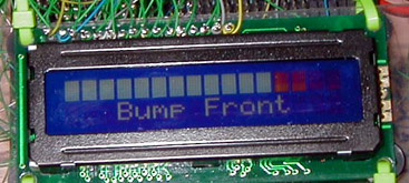
Above is a photo of our final bot. The top row is a bar graph of
ambient light. The bottom row displays information about the bot's
reactions.
If you have any questions, feel free to email me.
Happy
engineering!
20030225