CS184 AS5: Raytracer with Scene Hierarchy
DUE DATE: Sunday March 8th, 11:00pm
Aim
For this project we will extend the raycaster to become a full raytracer. We will model non-local illumination effects such as shadows, reflections and refraction. We will incorporate our knowledge from AS3 to import a scene hierarchy. Since we're importing a scene hierarchy, we will support arbitrary transforms on our spheres, so that we can make ellipsoids. We leave our "real-time" raytracer behind to generate more interesting images, but rendering times will go up significantly.IMPORTANT: To complete this project, you need to read the textbook's chapter 9 and 10.1 through 10.8, and chapter 6.2 though 6.5. Without it this assignment will be extremely hard! Please save yourself and us the trouble and read these chapters.
Minimum Specifications
For this assignment, write a program calledraytracer that accomplishes at least the following:
- Launch your raytracer using
raytracer scene.scd output.bmp, taking in one required argument, the scene to render. The scene file will contain your eye and viewport location, thus render the given scene for a given camera location and orientation. - Image Output: When the image is completely rendered, immediately write the image to disk according to the supplied output.bmp filename.
-
Transformations:
- Linear transforms on spheres: Support rotate, translate, and non-uniform scaling transformations on the sphere. The scene parser will load these transforms from the scene file into the Scene DAG for you as it did for as3.
- Ray transforming: Intersection tests with a transformed sphere is done by inverse transforming the ray, then testing it for intersection with the untransformed sphere. Supporting this will allow you to easily render ellipsoids.
- Note on Spheres: Since we support arbitrary transformations, all spheres can now be considered the unit sphere at the origin, with some compound transformation applied to them!
- Transforming Normals: However, the normal vector for the surface at the point of intersection is now calculated on the untransformed sphere, and needs to be transformed with an inverse transformation to be properly oriented in world space. Please see Shirley section 6.2.2 for details on transforming normals.
-
Scene Hierarchy:
- Load in a SCD_09 file similar to the scene files in as3.
- As for as3, the scene file parser will supply you with a DAG of all the objects in your scene. You need to traverse this to render the scene. While traversing, keep track of the current transform by using your own stack, since you don't have OpenGL's stack anymore. Fortunately, if you write this method as a recursive traversal, you can use the program's execution stack to keep track of transforms by passing transforms down as arguments to the traversal function.
- We do NOT store color or LOD data on the DAG for this assignment, so you do not need to keep track of any data other than the transformations (and the colors of the leaf spheres) as you traverse the DAG.
- For this assignment, you are only required to traverse the DAG once to build a flat representation of your scene, which you then use to render the scene. See the Implementation Tips section for details.
- Raytracing:
- Reflection: Create rays reflected off objects (the so-called "bounce ray") with some coefficient of reflection (
kr, the reflectivity of the material). These rays are again sent into the scene. To accomplish this, write yourraycast(Ray, depth)function in such a way that it can be used recursively. - Refraction: UPDATE: Refraction is now an extra credit option.
- Limited Bounce Depth: If the contribution from any secondary or higher-order bounce-ray is less than say 1/256, then that ray needs no longer be pursued. But just in case you scene is highly reflective and loss-less, also build in a limit for the number of consecutive bounce rays, i.e., terminate the recursive nature of raycasting after some specified depth. Set the default depth to 3.
- Falloff for Lights:
We want to model lights as dimming with distance, and be able to adjust
the factor by which this extinction occurs. This factor is already
included in the specification of each light, and is read into the light
class. Apply this falloff according to the absolute distance from the
light to the current location. Assume that all the light intensity
values are measured at a distance of one unit from the light. This
should make it east to apply falloff by measuring the pythagorean
distance
x^2 + y^2 + x^2 = (dist)^2and scaling the light's intensity appropriately.
- Reflection: Create rays reflected off objects (the so-called "bounce ray") with some coefficient of reflection (
-
Distribution Raytracing for Anti-aliasing:
- Multiple rays per pixel: Shooting only a single ray per pixel can result in objectionable aliasing effects; these can be reduced by shooting multiple rays per pixels and averaging the returned (r,g,b) intensities. Modify our Viewport class to shoot multiple rays per pixel. Each pixel should be sampled according to a regular grid (i.e. 2, 3, or 4 samples per pixel edge). This is equivalent of assuming that you have screen in which the number of pixesl in the horizontal and vertical directions are increased by an interger multiple. (In a more sophisticated program the individual super-sampling rays would be randomized in their positions within a pixel). The Viewport class is now initialized with a raysPerPixel value, so you can modify the constructor. This question should take very little work! all you need to do is modify the viewport to use floats for pixel values and iterating over smaller steps than one pixel when getSample is called.
- Capture
the RGB intensities of all the super-sampling ray
bundles in the Film class, and average them according to the total
number of rays per pixel. You need to build a buffer that stores pixel
values, and use OpenGL to iterate over the buffer, producing a
completed image when rendering is done.
Changes to the lighting model
Since we want a more accurate lighting model than the last assignment. What is important to note here is that we've separated the color of an object and the intensity of the light falling onto it. The S and C terms are color, and I is the intensity of light falling in. As discussed in lecture:

Idea for Extra Credit:
Again, in approximate order of easiest to most difficult.- Spotlights: Add spotlights, which are defined by a position, a direction, and an angular falloff value that determined how wide the spot is.
- Area Light Sources and Penumbras: If you want to see the nice soft shadow boundaries that are produced by light sources that cover a finite area rather than just a point, you can again use the super-sampling principle. You may replace a square light panel with an array of, say, 4 by 4 point lights.
- Depth of Field: Most of the moving parts needed to implement depth of field for realistic camera effects is in place. Implement DoF, making it available preferably as an argument in the Scene file (which required hacking our scene parser, a good exercise in reading code) or come up with some other way to enable and disable this.
- Refraction: UPDATE: Refraction is now extra credit! Create rays that travel through the material depending on a coefficient of refraction (
ktthe transparency of the material andktnthe refractive index of the material). These rays should bend according to Snell's Law. Assume that the air has a refractive index of 1 (thus, the "n" value for air in snell's law is 1).
Additions to the Scene Description
The scene description now includes the following statements:
(sphere id
(radius radius_float)
(material material_id)


				)
(material id
(color color_triple )
(ka ka_float) # diffuse reflection coefficient for ambient light (hack!)
(kd kd_float) # diffuse reflection coefficient
(ks ks_float) # specular reflection coefficient, aka "kr"
(ksp ksp_float) # specular angle fall-off
(ksm ksm_float) # metalness
(kt kt_float) # transmission coefficient
(ktn ktn_float) # refractive index
)
(camera id
(perspective 0|1 ) # (perspective 0) means parallel projection
(l l_float) # left boundary of window in the image/near-clipping plane
(r r_float) # right boundary of window in the image/near-clipping plane
(b b_float) # bottom boundary of window in the image/near-clipping plane
(t t_float) # top boundary of window in the image/near-clipping plane
(n n_float)
# sets the -z coordinate of the image plane, and of the near-clipping plane(f f_float)
# sets the far clipping plane; this is typically not used for raytracing.

				)
(type lighttype_flag)
(color color_triple )
(falloff falloff_float) # falloff exponent for point- and spot-lights
(deaddistance deaddistance_float) # dead_distance for point- and spot-lights
(angularfalloff angularfalloff_float) # exponent on cosine for spot-lights
# by default localized lights are positioned at (0,0,0)
) # and directed lights are shining in the direction (0,0,-1).
Note that positions and orientations are not specified directly because they can be specified using transformations. If untransformed, all objects are at (0,0,0) and all directions are (0,0,-1).
Note that the frustum is specified by the opengl convention: the l,r,b,t specify a rectangle the near plane z = -n. Therefore, for example, the upper left corner of your screen would be placed as UL = vec4(l,t,-n,1);
Although the scene format support multiple named cameras, we do not provide a way to specify which camera is used for rendering. Therefore, for now you may choose your camera arbitrarily in any scene with multiple cameras.
Example Scene (for submission)
Here is an example that recreates the scene from as4, while you wait: threespheres.scd. This should look like: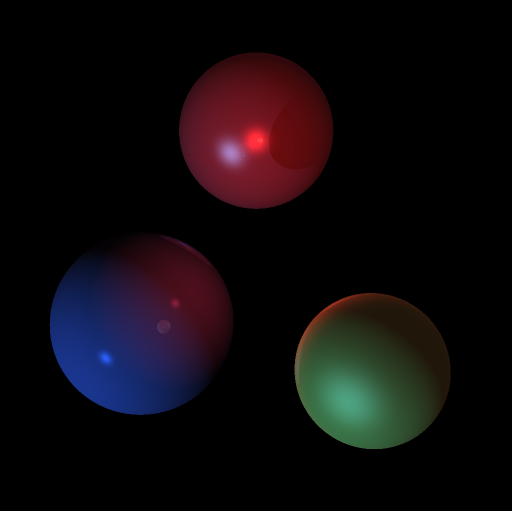
UPDATED SATURDAY MARCH 7th: The falloff exponent was corrected from 0.6 to 1.0, and all materials now have a metalness of 1. For submission purposes, please render THIS scene file. The output, if rendered with 4 rays per pixel (2 by 2 in a grid) should look like this:
Submission
To submit this project, all of the following needs to be done by the deadline:- Submit using the submit as5 command on the INST machines:
- A copy of your code, including the whole framework, the compiles on the platform you developed on.
- A README.txt containing: Your name, SID, Login and a description of the platform your code compiles on.
- TWO images generated by your raytracer. One image of the supplied scene, and one of a modified scene that you can do with whatever you want.
- ONE scene file corresponding to the modified scene you created. Be Creative! Be Grand! Be Awesome! Make the art students jealous! Make the architecture students swoon! Make the mechanical engineers excited! Make the teaching team go "2 points of extra credit!"
- Put on your class instructional website:
- A separate page for this assignment.
- On this page, the images you are turning in, as well as the scene and OBJ files for them.
Windows Users: The grader should ONLY have to open your .sln file and press F5 to build and run your solution.
*Nix Users: The grader should ONLY have to run make with the appropriate makefile to build your project. Thus, for Mac and Linux
make and for solaris gmake.
Note: The submit program retains the directory structure of what you send it. Thus, we recommend making a new directory for your assignment on the server, cd'ing into that directory, copying the whole framework with your code into this directory, and running
yes | submit as5 to easily submit the whole project to us.
Framework
For this project we have released a patch for your as4 project to help you read scd files: as5update.zip. Add the included files to your project -- note that in visual studio you may need to do this manually.
Implementation Tips
This project consists of four main ideas -- 3D transformations, scene hierarchies in 3D, recursive raytracing, and super-sampling. First build out the scene hierarchy details, then worry about implementing raytracing and supersampling, since these two are independent of one another.Suggested changes to as4 framework
- In algebra3.h, you will probably want to update or remove the assignment operator for the Material class; it does not assign quite enough.
- In Viewport.h, you may want _i and _j to be floating point values, not integers, when you shoot multiple rays per pixel.
- In main.cpp, you will probably want to remove the timer callback which attempts to update the display at 30 fps, as it will just make you sad.
DAG Traversal and building a scene description
For this project you only need to render a single frame - animation and interaction is not supported. We suggest you use this to your advantage by traversing the DAG once to build up a flat representation of your scene. A suggestion for this flat representation is to use a vector of instances, each containing the transform and inverse transform for an object, and a pointer to the object for which this is an instance. The following diagram should explain what we suggest you build up from the scene DAG: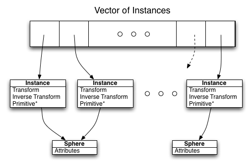
Inside vs Outside a sphere
Consider the only difference between coming from the inside and coming from the outside
of a sphere. For one, the surface normal and the incoming ray forms a certain set of angles, and for the
other it forms another, disjoint with the previously mentioned, set of angles. Can you use this and some dot products
to write your refraction code quite general?
Do NOT calculate the exitance ray directly from the incidence ray in dealing with the sphere's refraction.
Falloff
We do not attempt to accurately model falloff, only to get some of its effects. Thus falloff is only calculated for the lights in doing direct illumination on an object. Reflections and Refractions don't have to get "weaker by distance". See the newsgroup for a detailed discussion on how to implement falloff in terms of the deaddistance and angular falloff/coefficient..