Overview
The goal of this project is to design a pinhole camera ("camera obscura") to capture light reflecting off an object into the hole to the screen (white paper in the box). This image is then captured on a camera with a long exposure time.
Pinhole Camera Design
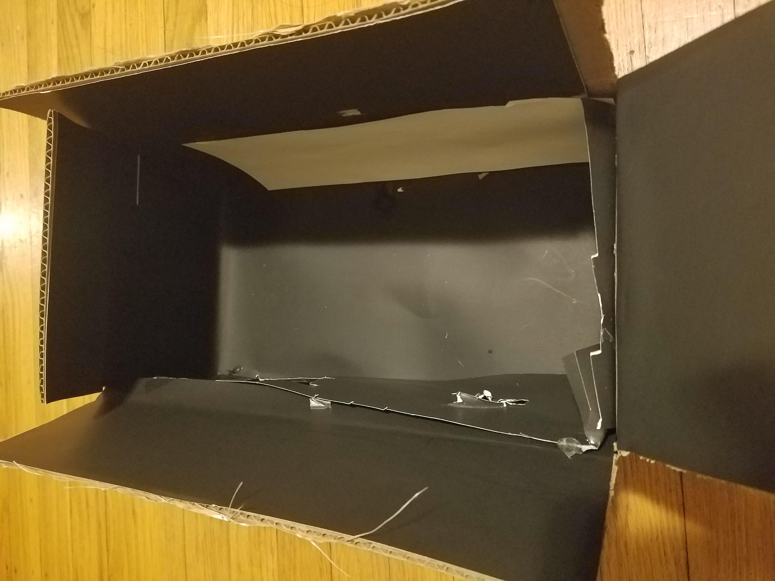
I covered the inside of the box with black paper except one side, which was covered with white paper and acted as the screen for the projected image.
On the opposite side of the white paper, I made two holes, one for the pinhole and the other for the camera.
To vary the size of the pinhole, I had different cards with different sized holes poked into them. I would then tape the card with the pinhole size I needed.
I calculated the optimal pinhole size using the formula 1.9 * sqrt(f * lambda), where f = 170 mm and lambda = 550 nm and the size
I got was about .6 mm. So I used .6 mm, 3 mm, and 5 mm diameters for my box.
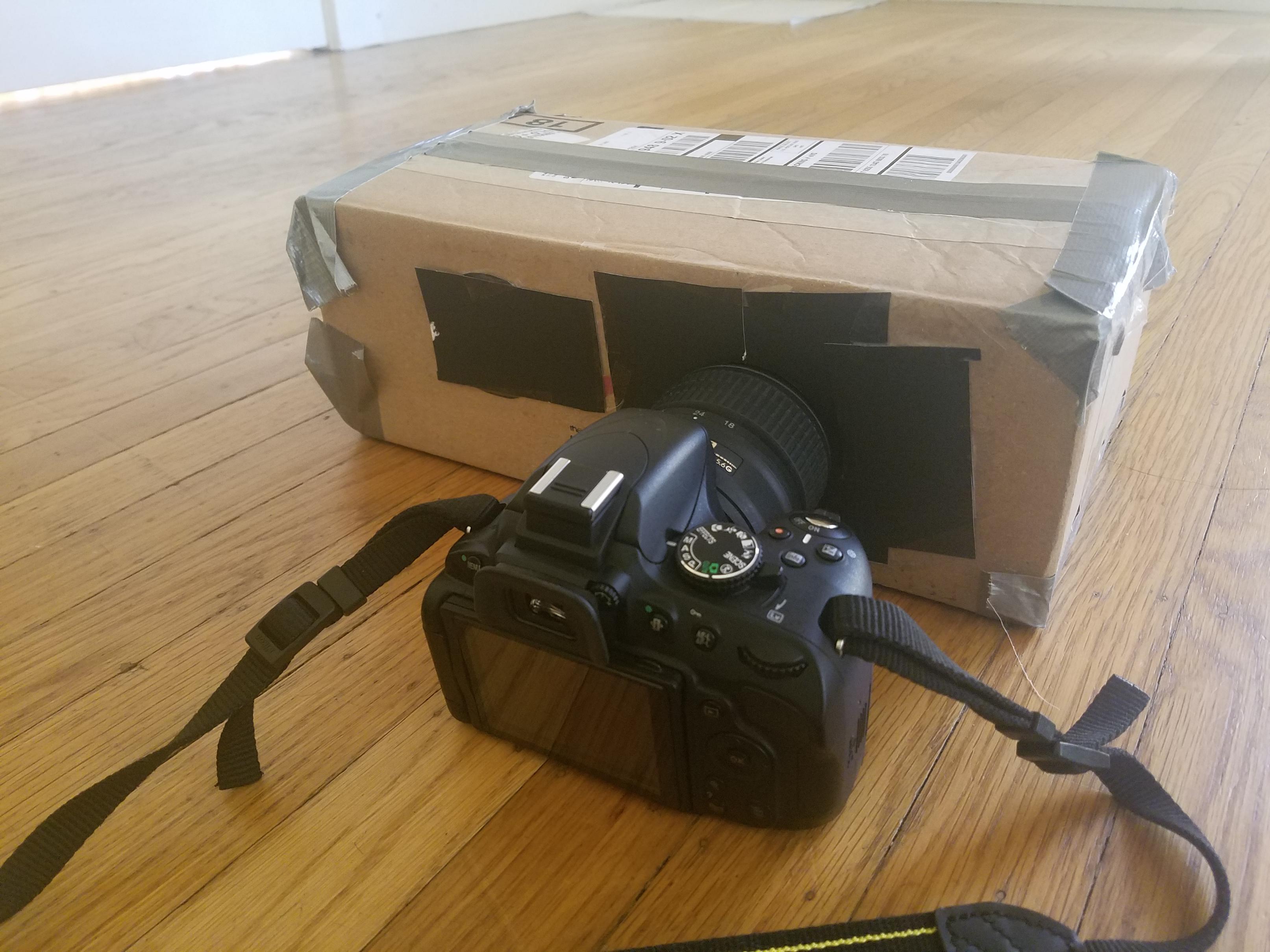
For the camera settings, I used the maximum shutter time available on my camera, which was 30 seconds and set f-stop to f/4 and ISO to the highest setting.
I also taped all the sides of the box to ensure no light would leak through. Then, I attached my camera to it, resulting in the finished model.
|
|
Images
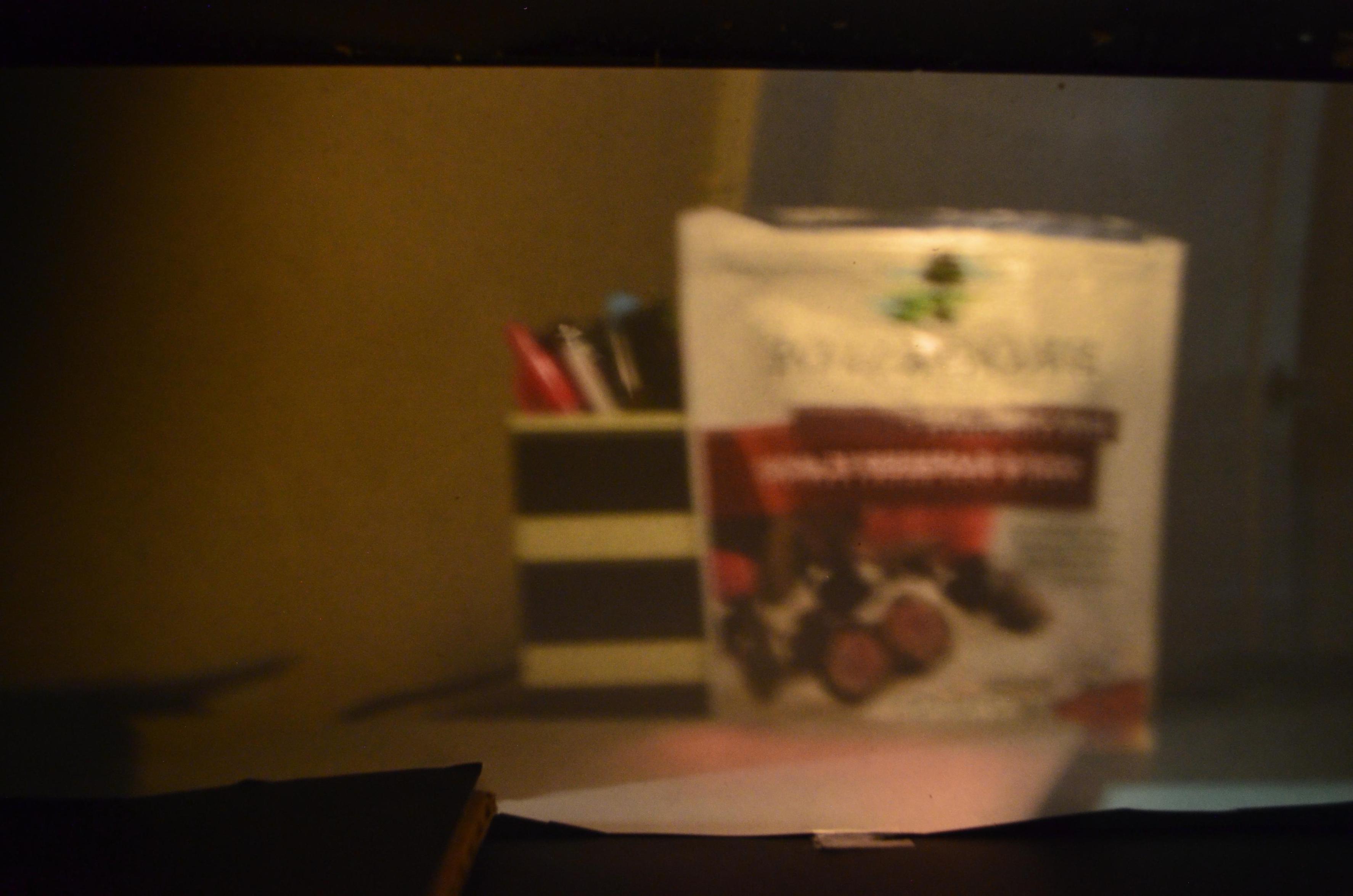
Scene 1

|
||
|
|
|
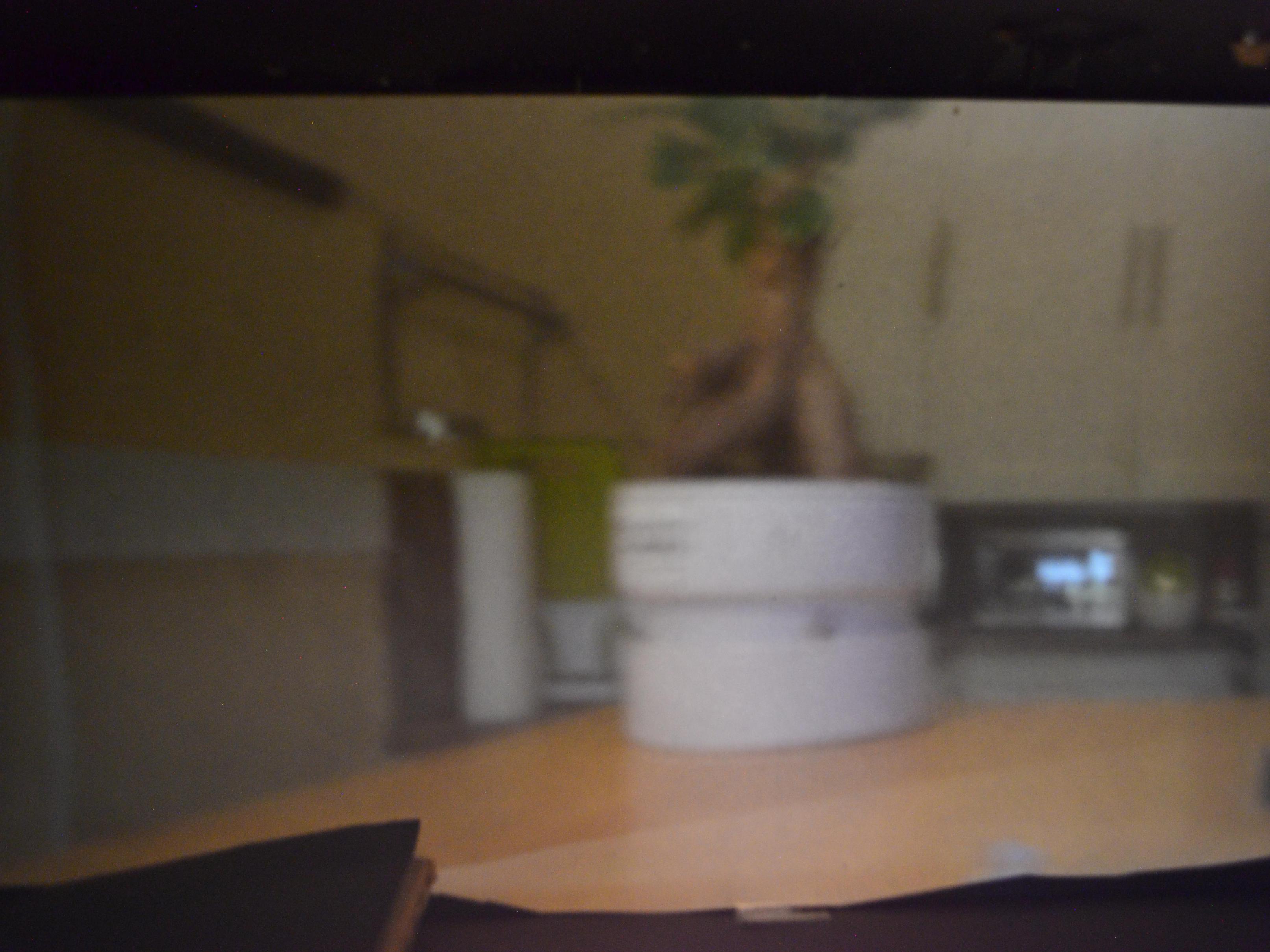
Scene 2

|
||
.jpg)
|
.jpg)
|
.jpg)
|
Scene 3

|
||
.jpg)
|
|
.jpg)
|
Observations
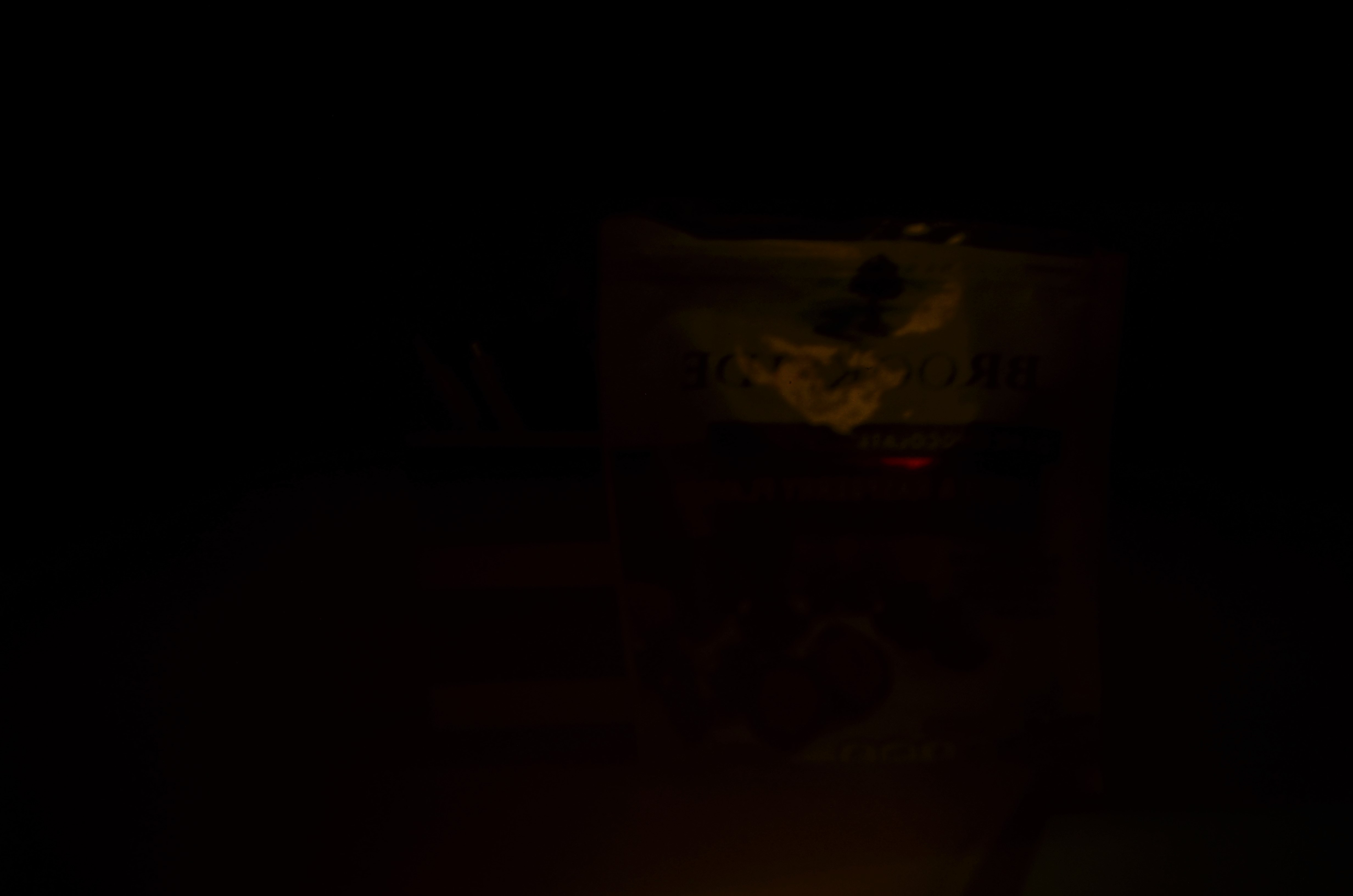
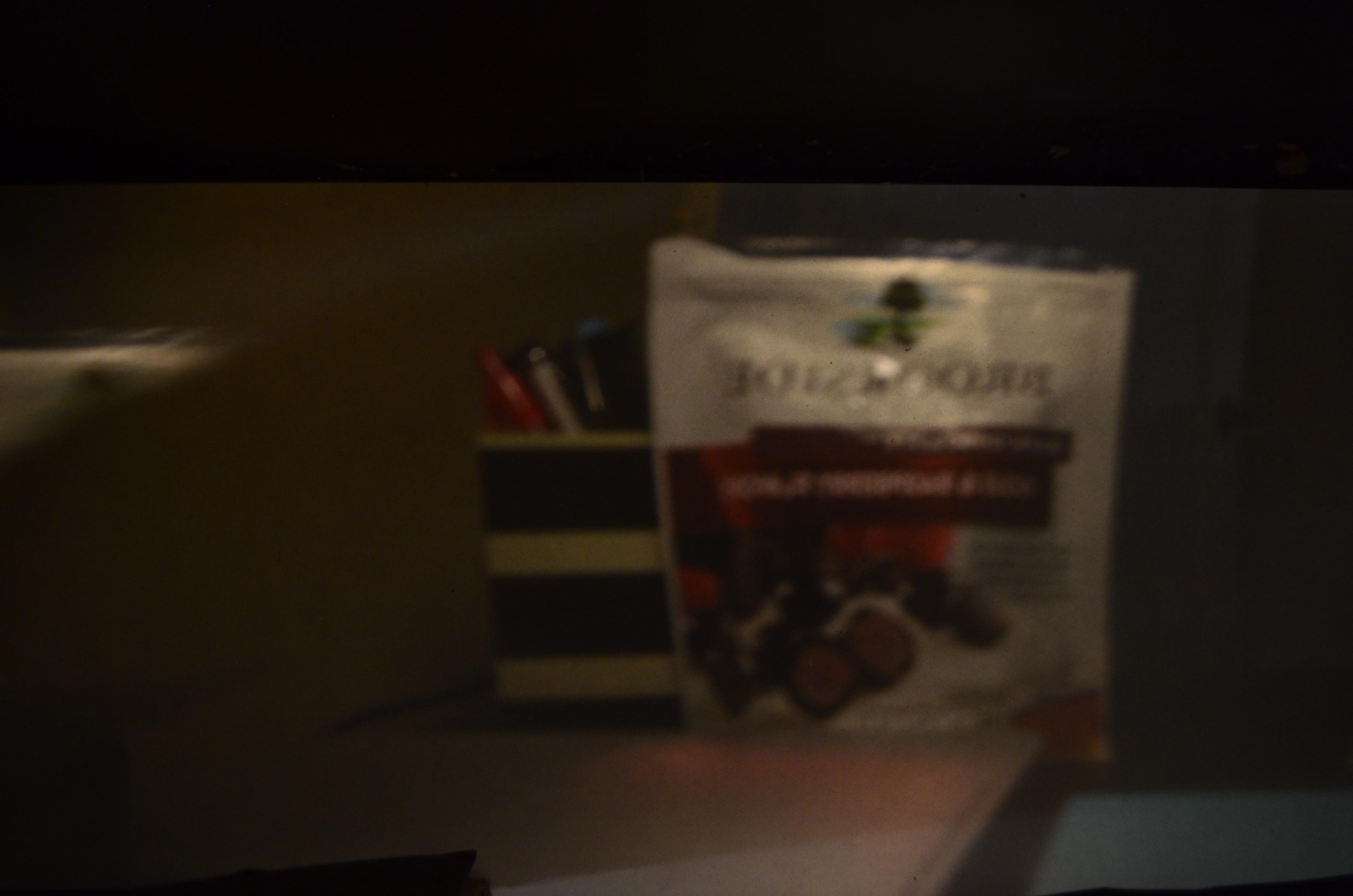
Images taken with the largest pinhole were the brighest while images taken with the smallest pinhole were very dark. Because larger holes allow more light in, the images projected onto the screen are brighter but they are less focused and more blurry because more rays enter the box. When the pinholes are smaller, less rays come in, making the image darker but these few rays are able to mostly intersect at one focal point, making the image more in focus.
And all this can be seen in the images above, although it's a little hard to tell how in focus the .6mm pinhole images are because of how dark they are.
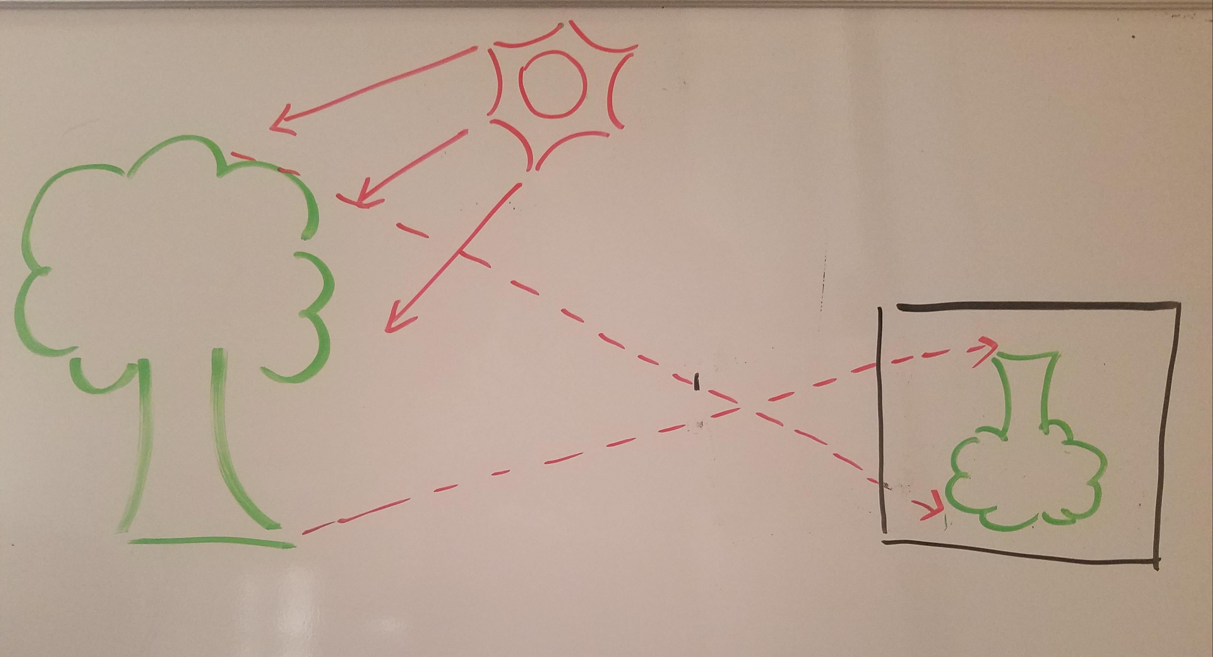
Additionally, the images were upside down and flipped but I rotated the images (but didn't flip) the images shown on the webpage. But this makes sense as rays at the top of an object are projected down at the screen and vice versa for the rays originating from the bottom of the object, as seen in the diagram below. And the same logic applies to the left->right, right->left of the image.
|
.jpg)
|
Bells and Whistles
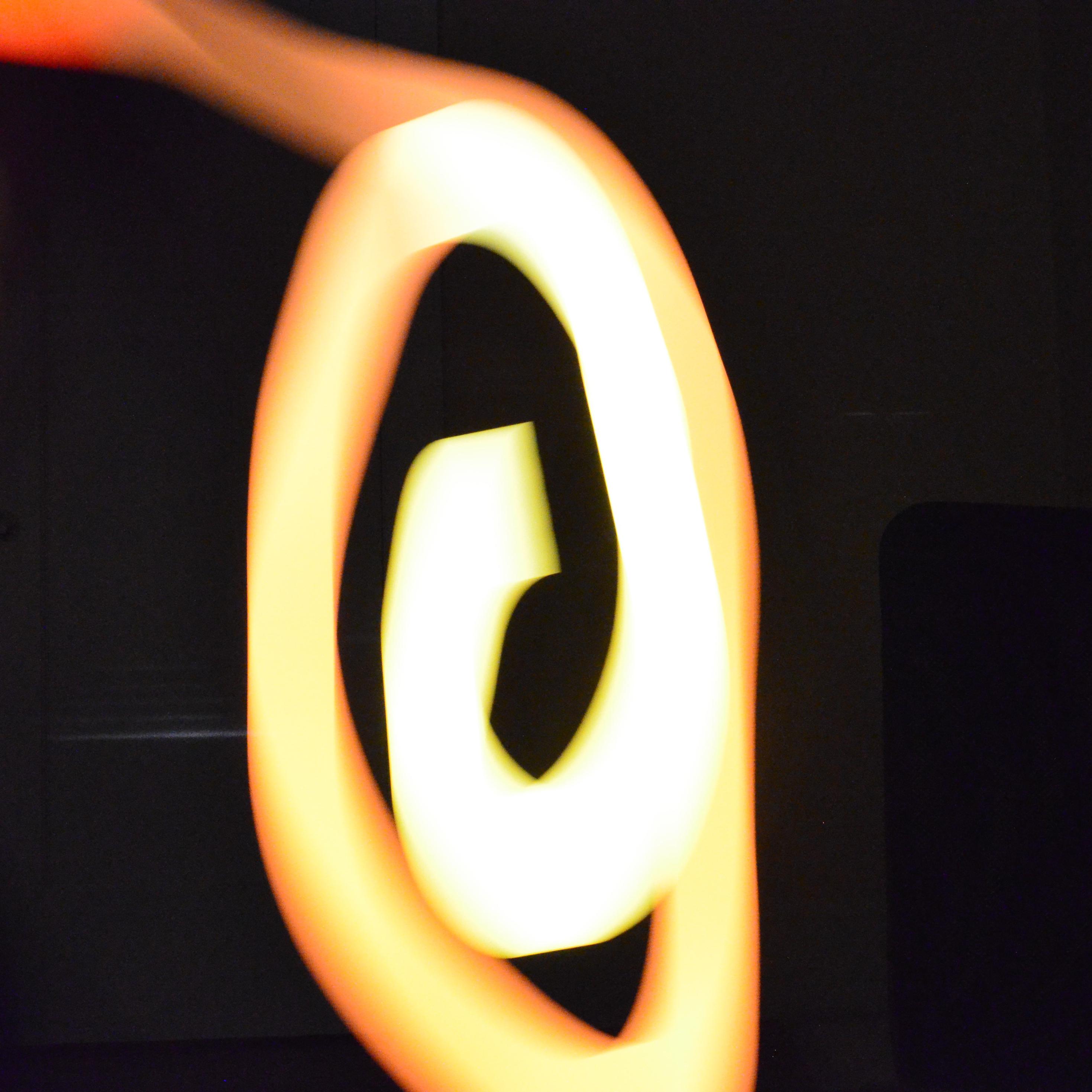
Light Paintings
|
|
|
|