Overview
A pinhole camera, also known as a "camera obscura", was an early form of the modern-day camera. The device consists of a dark box, with a pinhole on one face, and a "screen" on the opposite face. Light from the scene enters through the pinhole, and is projected onto the screen. This projection is the captured image of the scene, and once inverted horizontally and vertically, is the faithful photograph we know today.
Design Process
We obtained a shoebox, and measured its dimensions to calculate the ideal pinhole size. Our shoebox was a very rectangular shaped prism, so we chose the large faces to be the faces for the pinhole and the screen, because we wanted adequate space for the projection on our screen.
The formula for the pinhole size is 1.9 * sqrt(f * lambda) , where f is the distance from the pinhole to the screen, and lambda is the wavelength of light (~550 nm). We measured f to be 10.5 cm (105 mm), and calculated the pinhole diameter to be about 0.46 mm.
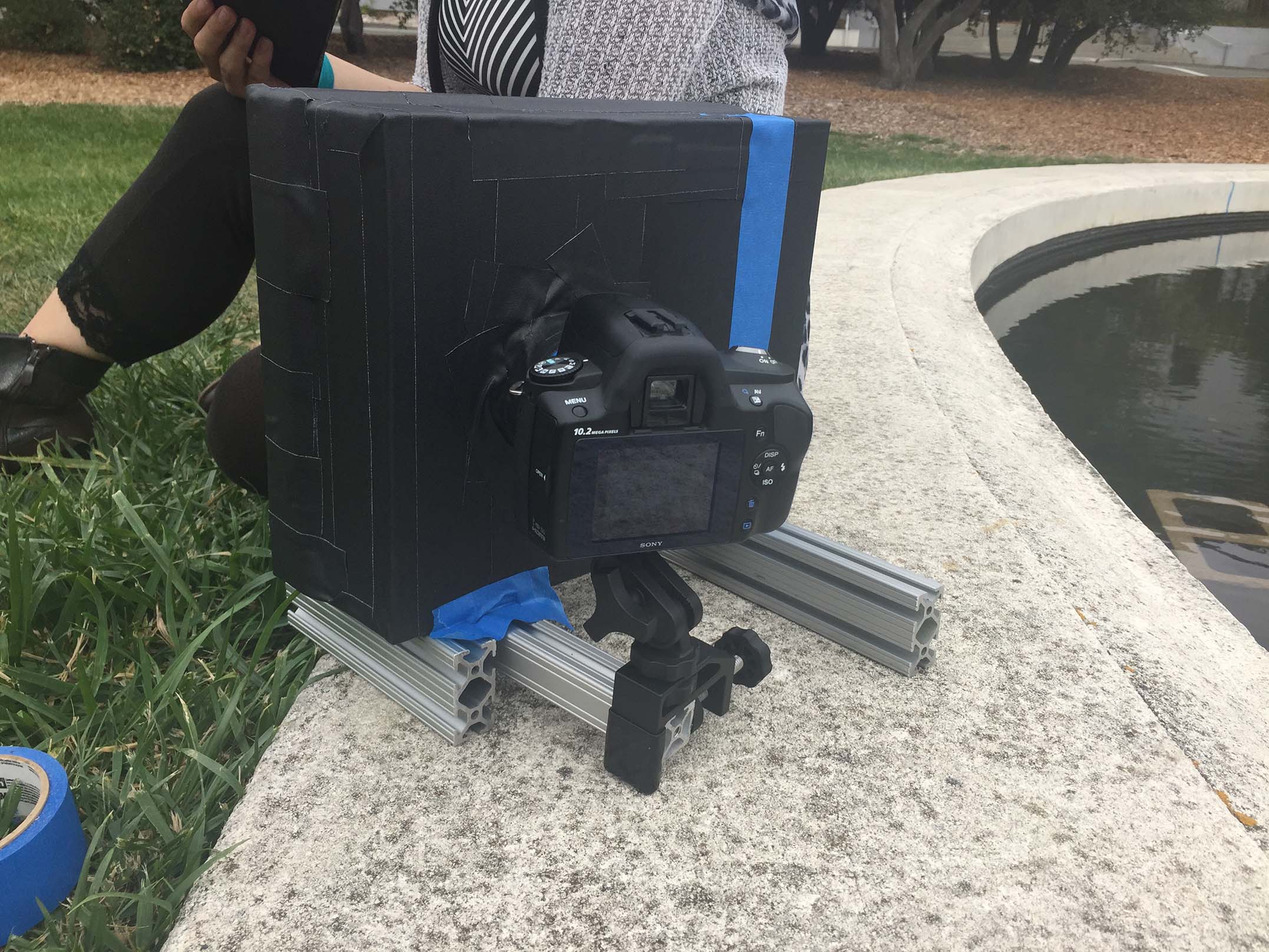
Using this size (to the best of our hole-punching ability), and trying out sizes a bit smaller and larger as well, we started out with 3 pinholes diameters: 0.36 mm, 0.5 mm, and 1 mm. Then we constructed our pinhole camera: glued a white piece of paper to the inside of our box as the screen, covered the rest of the inside of the box with black paper, cut a hole on the pinhole box face to stick our digital camera in, in order to capture the projection on the screen, then cut a hole and constructed a little frame, so we could easily slide our pinhole cards in to change the size of our pinhole. Taped up the entire contraption with black tape to 1) really not let light in, and 2) hold the whole thing together; built a little stand for the digital camera to sit on, then voila! We had our pinhole camera.
Pinhole Camera with no card

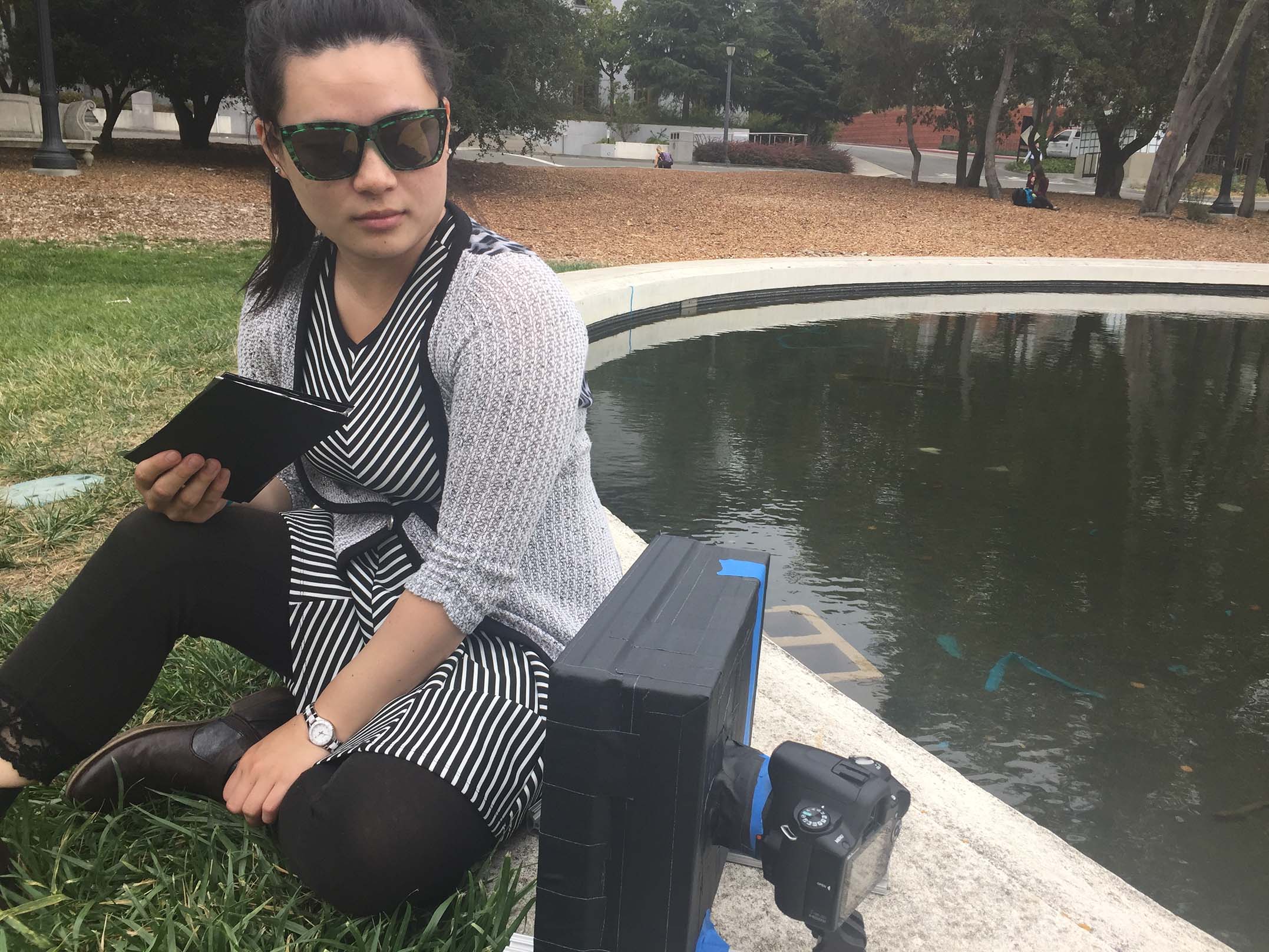
Camera with Alice (looking fly)
Closeup of camera setup
When we went out to test our camera obscura though, we ran into some problems. All the images we took were extremely dark, and absolutely incomprehensible. We couldn't get an actual image of the scene. We realized we weren't getting enough light to actually form an image, so we decided to make larger pinholes, and test them out. Larger pinholes made a dramatic difference . We were now actually letting in enough light that our digital camera could take a visible picture of the projection. The pinhole sizes we ended up using were 1 mm, 3 mm, and 5 mm.
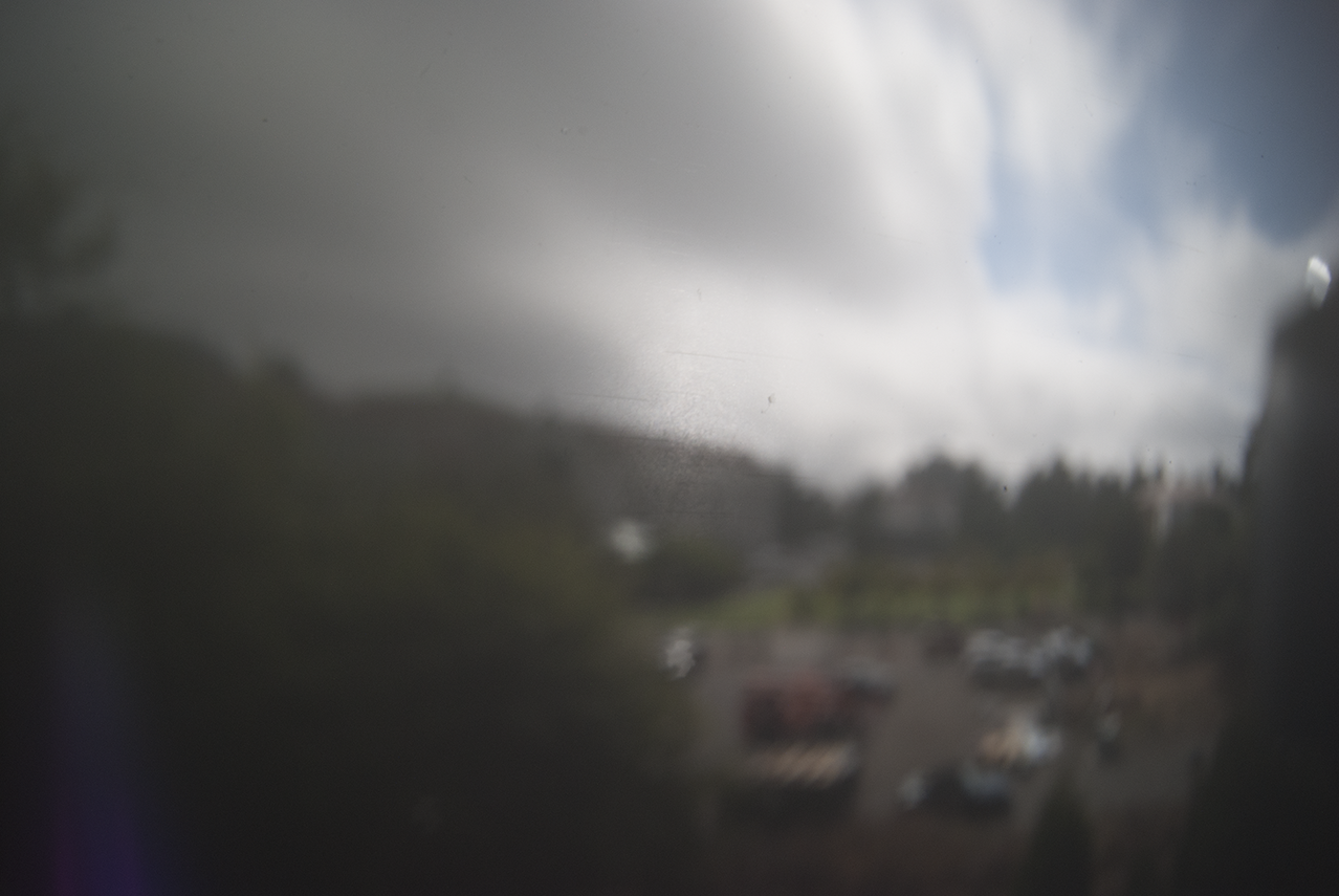
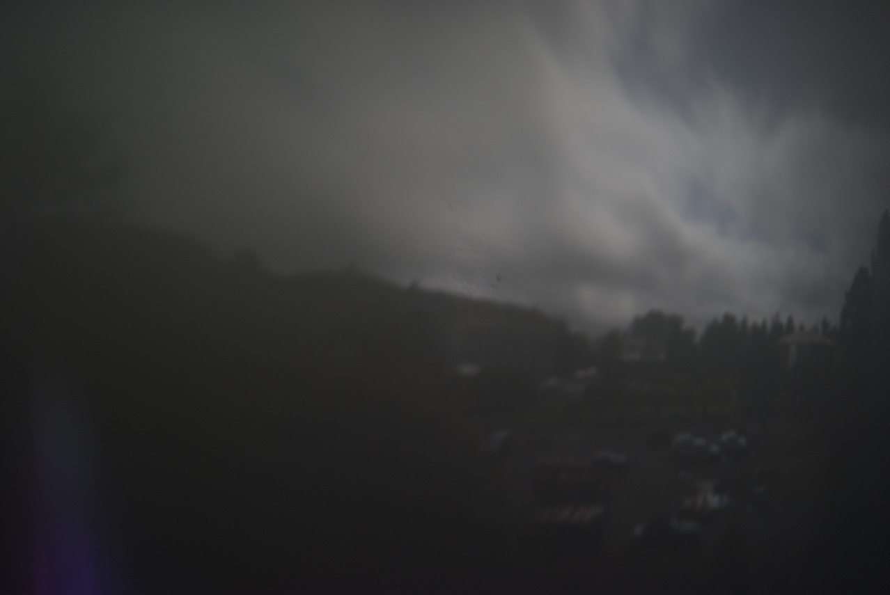
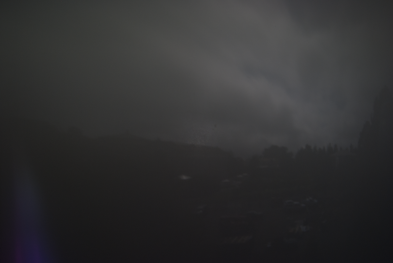
There is a tradeoff that happens in going from large to small pinholes, and vice versa. Larger pinholes let in more light, which could make an image more visible, but they can also make an image more blurry, because multiple rays of light, from a single source, can enter and project onto our screen, and this overlapping of light from different points will make our image less crisp. Smaller pinholes will alleviate this blurry problem, but they allow in less light, which might make for a very dark picture, and also, will only help the blurriness to a certain extent. Once the pinholes get too small, physics kicks in again, and the wave-particle duality of light becomes relevant; namely, we'll get interference, because light is also a wave. This tradeoff is visible in our comparison images (shown below): the pictures taken with larger pinholes tend to be lighter and more visible, but also blurrier.
Note: this project was done during a rather odd period of time in Berkeley, weather-wise. In particular, on the day the comparison images were taken, clouds were quickly alternating between covering the sun, and not covering the sun. So some changes in lighting between pictures from different pinholes may be due to the weather as well.
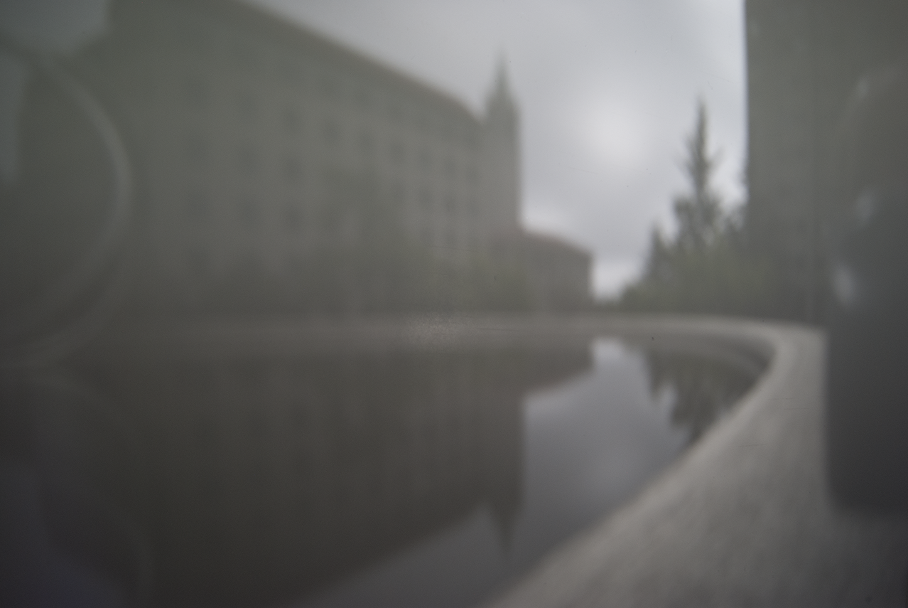
Ultimately we came to the conclusion that our box was simply not large enough to find the correct balance between darkness and focus. Future improvements to the camera would be to make the focal length of the box larger so that a larger hole can be used to allow maximal light and focus. We decided to use the small, 1mm pinhole as a compromise because it allowed enough light for an image to form with minimal blurry-ness. To account for how dark the images ended up, we increased the ISO value on the digital camera to allow the output values to have higher intensity. This ended up washing the images out a little bit, but allowed for a comprehensible image to form.
Comparison Images
Images taken with all 3 pinhole sizes:
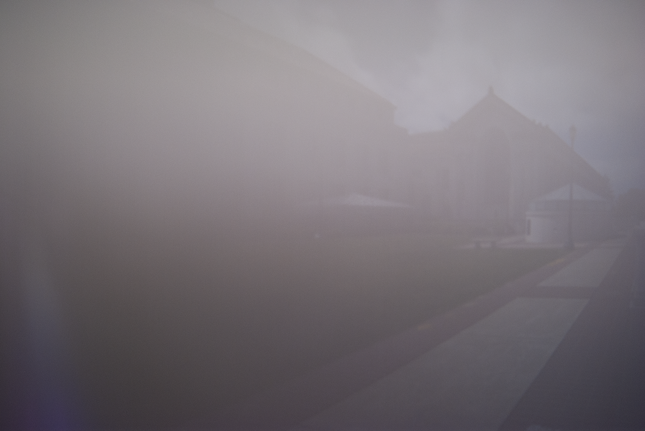
Hearst Memorial Mining Circle
5 mm
3 mm

1 mm

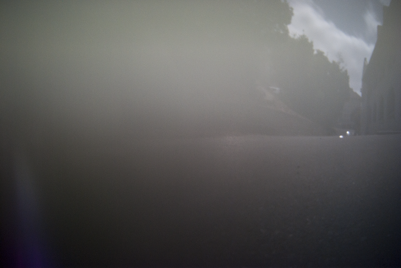
View of Memorial Glade
5 mm
3 mm
1 mm
Even More Images
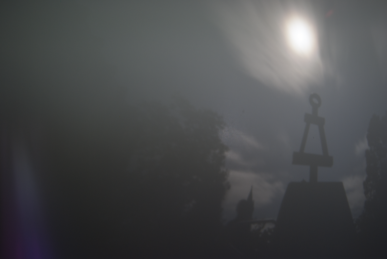
Looking at the 2 sets of images above, we decided that 1mm was the best pinhole diameter to use, to demonstrate that we understood the correct focal length that we should use.
Below are some additional images using this pinhole size:
Tau Beta Pi Bent
Doe Library
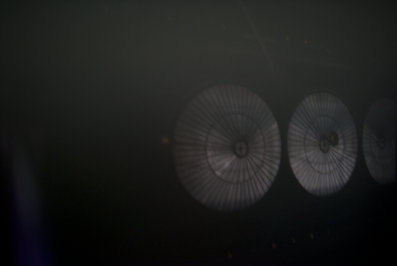
HMMB Alley
HMMB Skylights