Building a Pinhole Camera
Project 2 - Computational Photography
Phillip Kuznetsov
cs194-26-aea
Utkarsh Singhal
cs194-26-aem
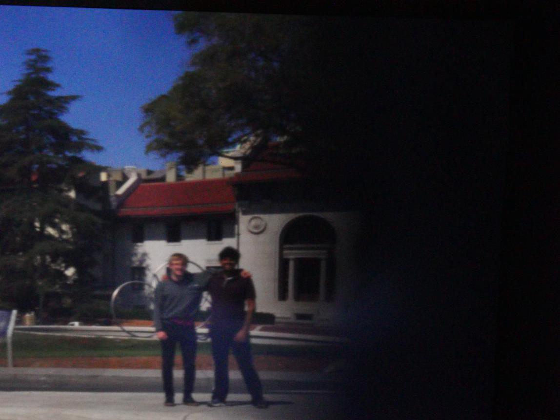
Self portrait of the project members
Pinhole cameras are one of the simplest cameras that you can make
today. The basic idea behind the Pinhole camera originates from the
Camera Obscura. A Camera Obscura (latin for "dark room") basically is
composed of a dark enclosure, where one wall has a small pinhole
that lets in only a very small amount of light. This pinhole restricts light in
such a way that the image of any object in front of the pinhole is
projected upside down and mirrored on the opposite wall.
The pinhole extends this concept by trying to capture the light project onto
the opposite wall using either Film or by using a digital camera.
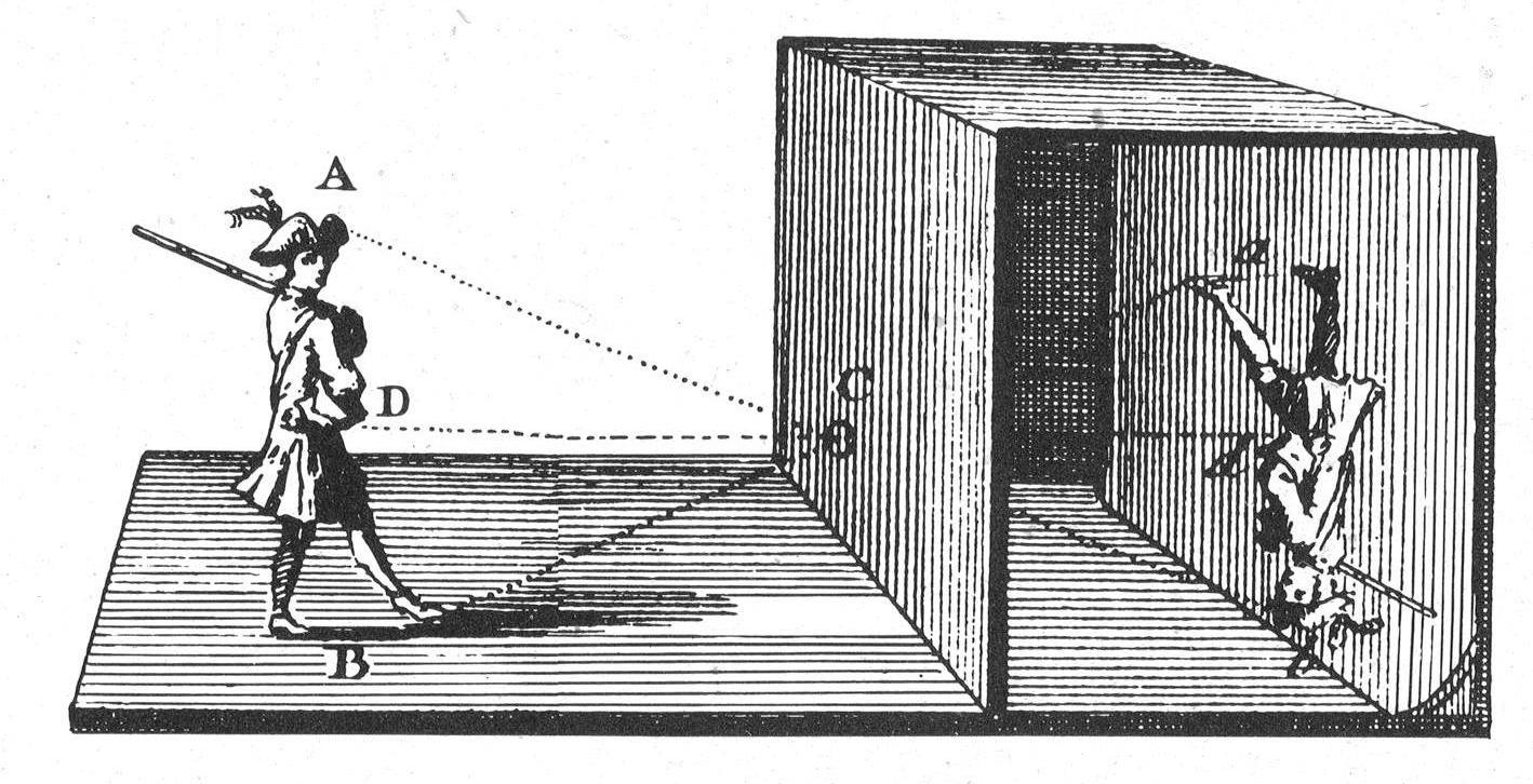
Camera obscura, from Wikipedia
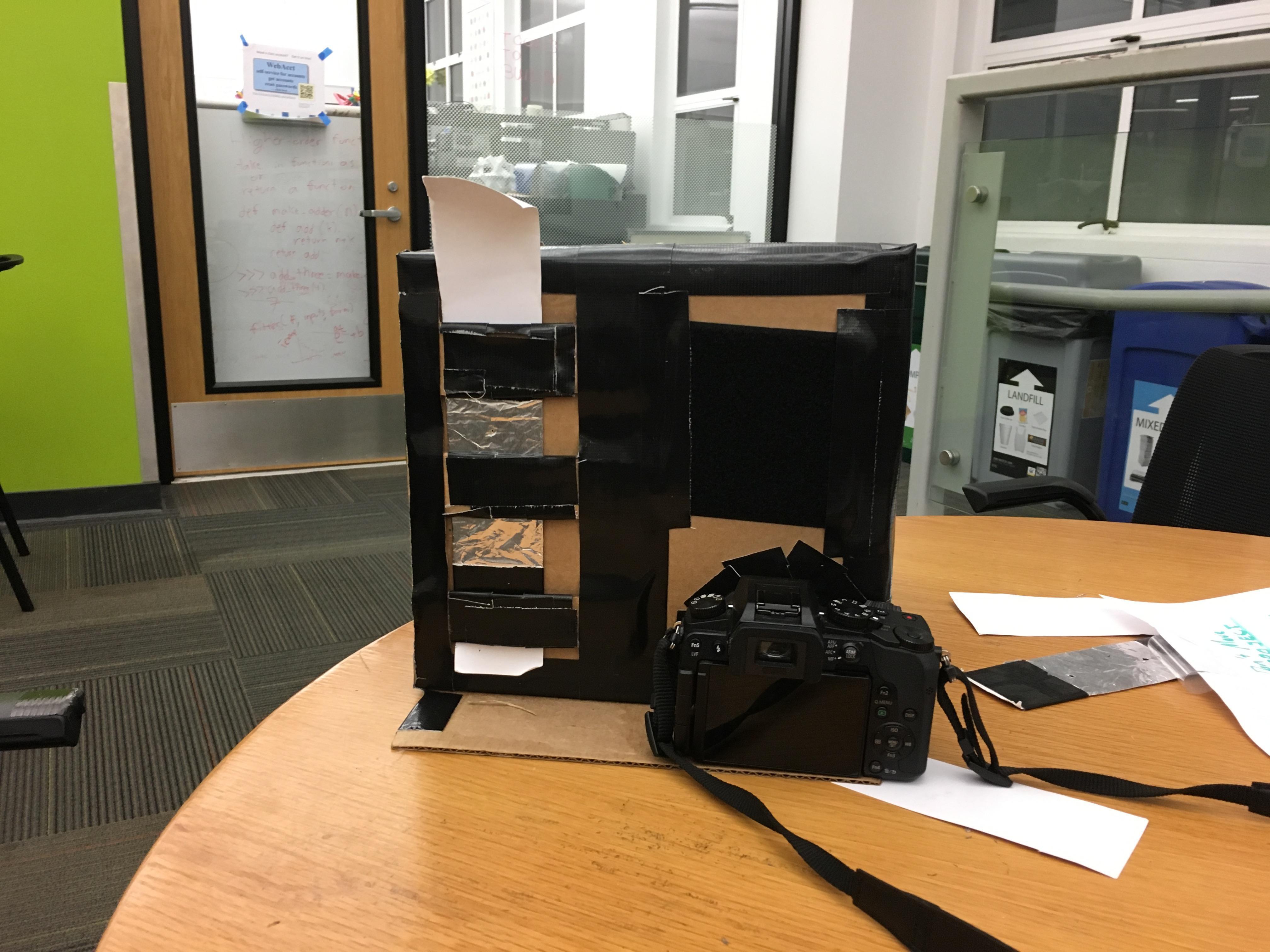
Our pinhole camera
The pinhole camera that we built does the latter - we project against
the wall of our camera opposite the wall with the pinhole, point a DSLR
camera at the wall, then snap a long exposure.
For the first part of this writeup, we display the images that are taken
using a standard pinhole camera with a single pinhole. We cycle through 3 different
pinhole sizes demonstrating the effect of these sizes on the focus
of the image.
Then for the second part we explore several bells and whistles
Construction
Materials
-
Our basic pinhole camera required these materials:
- A cardboard box, about the size of a shoebox
- Black duct tape
- Black construction paper
- Aluminum foil
- White Cardstock
- Velcro strips
- Anaglyph 3D glasses
Assembly
One of the most important parts of a pinhole camera construction is light-proofing the box. In order to ensure we had no light leakage, we took a think cardboard box and sealed every edge and every corner of it with black duct tape. We also covered the insides of the box with black construction paper to reduce internal reflections, and used white paper as the screen for our images. Any left over patches were painted over using black acrylic paint. This was followed by two 5mmx5mm openings for apertures (we made two holes because we wanted to do anaglyph imaging). We also cut out a hole for the camera, and liberally used duct tape to make everything light-proof and snug.
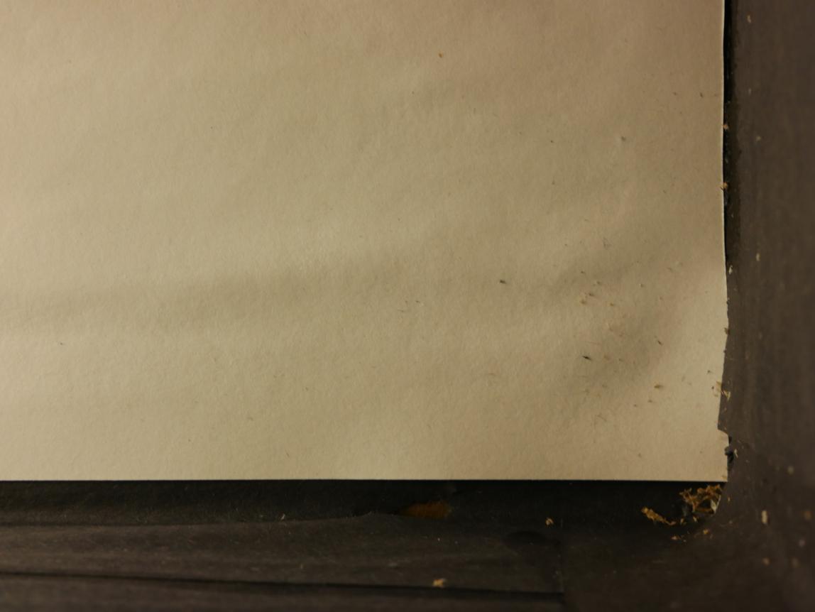
The view of the screen with good illumination from the perspective of the camera
Next part of the construction process were the pinholes. We wanted to be able to easily adjust aperture position and size, so we designed a system of swappable apertures. The pinhole is not located on the box itself, but rather on a swappable strip of paper that is held tightly in place using slots made from cardboard. All we need to do in order to change our aperture size or shape is to slide the desired aperture strips into their position. We can also move the aperture a little bit to adjust the image location for best results.
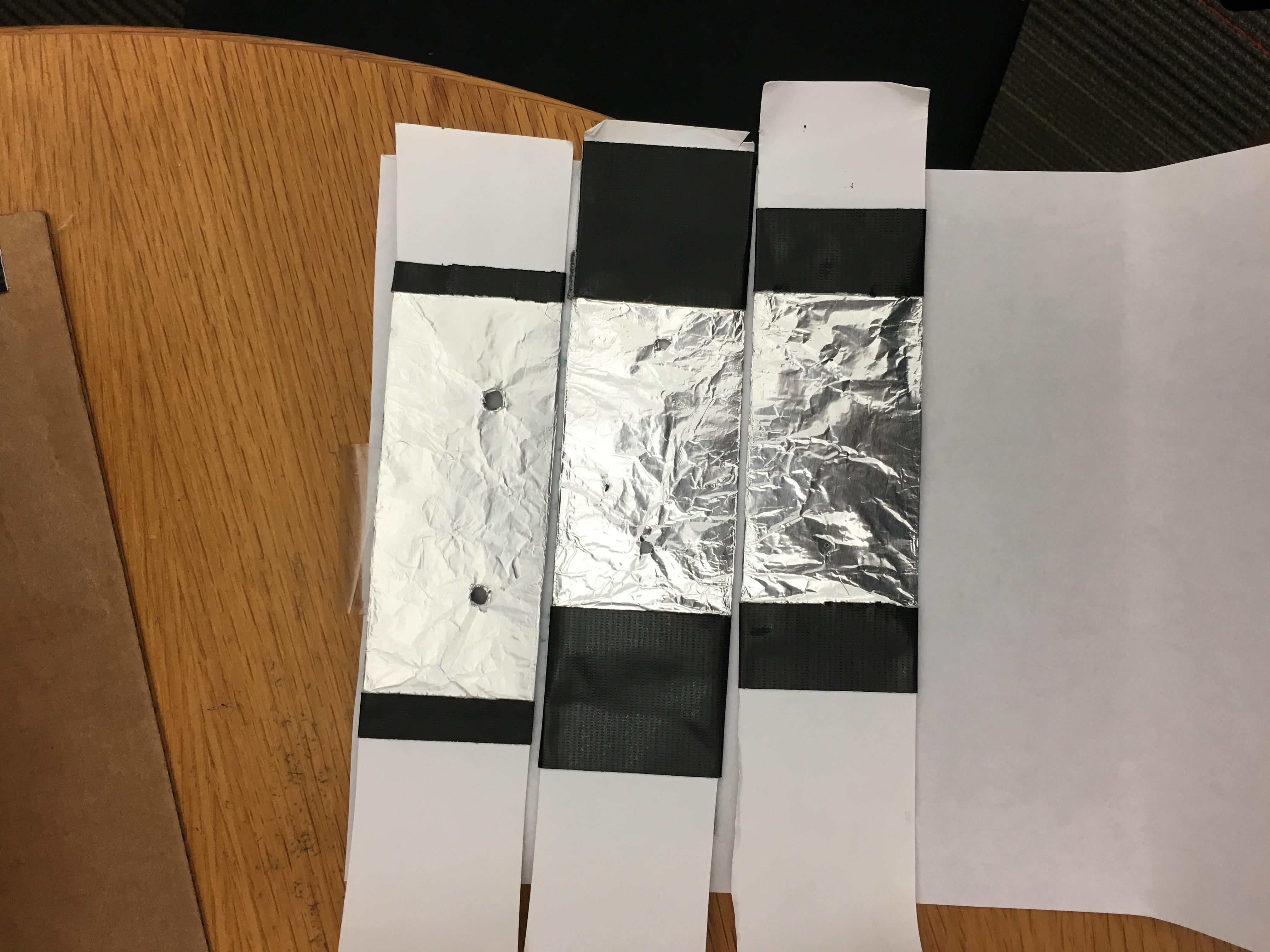
The different filter sizes. 5mm on top, 3mm in the middle and 1mm on the bottom.
An aperture strip is essentially a strip of thick white index paper with aluminium foil stuck on one side of it. We found this to be more effective at blocking light than using thicker paper. The aluminium foil also lets us make our pinholes more precise as compared to paper, which creates a lot more debris when pierced with a needle.
We used a detachable strip of velcro to seal the hole that we didn't need while taking normal images. The structural integrity of this whole assembly relies heavily on duct tape.
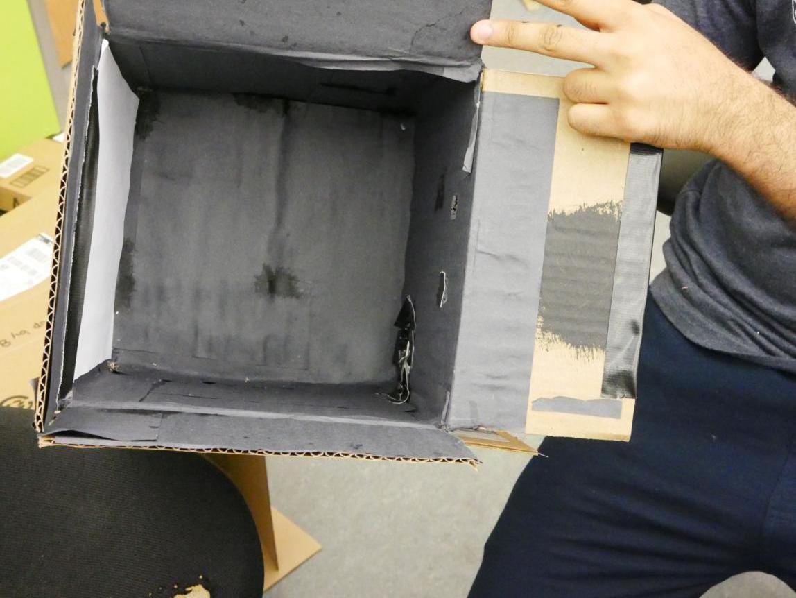
The inside of the box
Results
For the results, we had to flip the image vertically. This is because
the pinhole camera produces a vertically mirrored image due to the
function of the projection
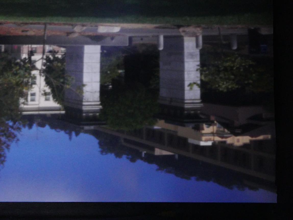
original image
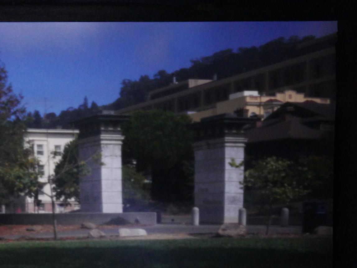
flipped image
Pinhole size comparision
We wanted to evaluate the effect of a varying pinhole size on the
quality of the image produced by the camera. We did this comparison with
two different locations.
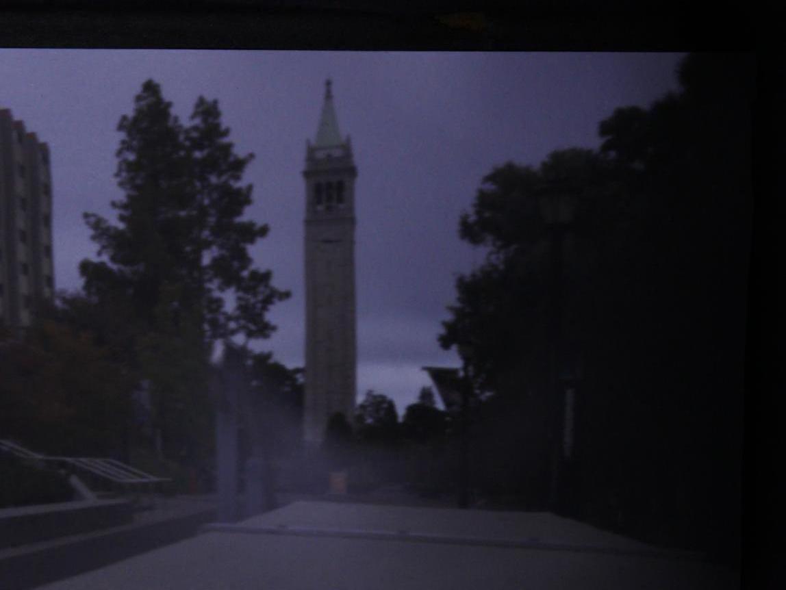
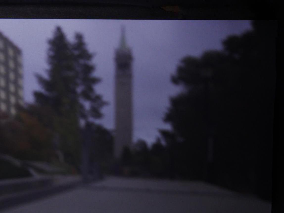
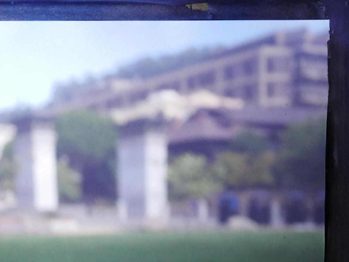
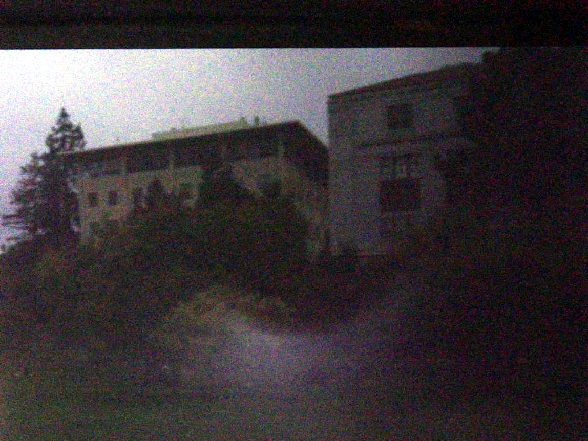
Campanile
1mm pinhole
3mm pinhole
5mm pinhole
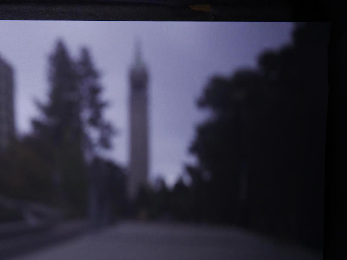
These images were taken on a very cloudy day, so they are much darker than the others.
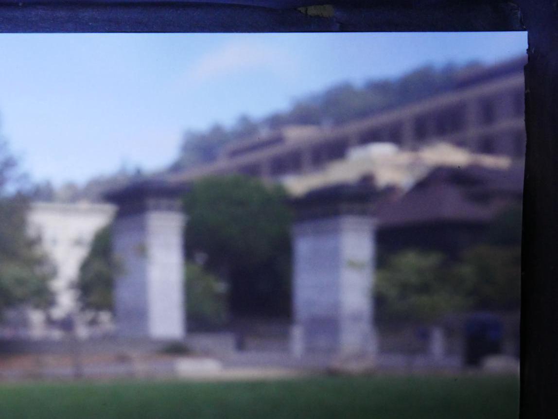
North Gate
1mm pinhole
ISO 3200; Exposure time: 30 seconds
3mm pinhole
ISO 3200; Exposure time: 10 seconds
5mm pinhole
ISO 3200; Exposure time: 10 seconds
As you can see, a smaller pinhole produces the sharpest images, while 5mm
produces the most blurry images. In the second set of pictures, you can
also see the change in brightness that occurs with the larger pinholes.
Larger pinholes let in more light, causing the resultant image to be much
brighter when compared to images that have smaller pinholes, but the same
photographic parameters.
More Pinhole Images
The following four photos were taken with the 1mm filter because it
produced the sharpest results.
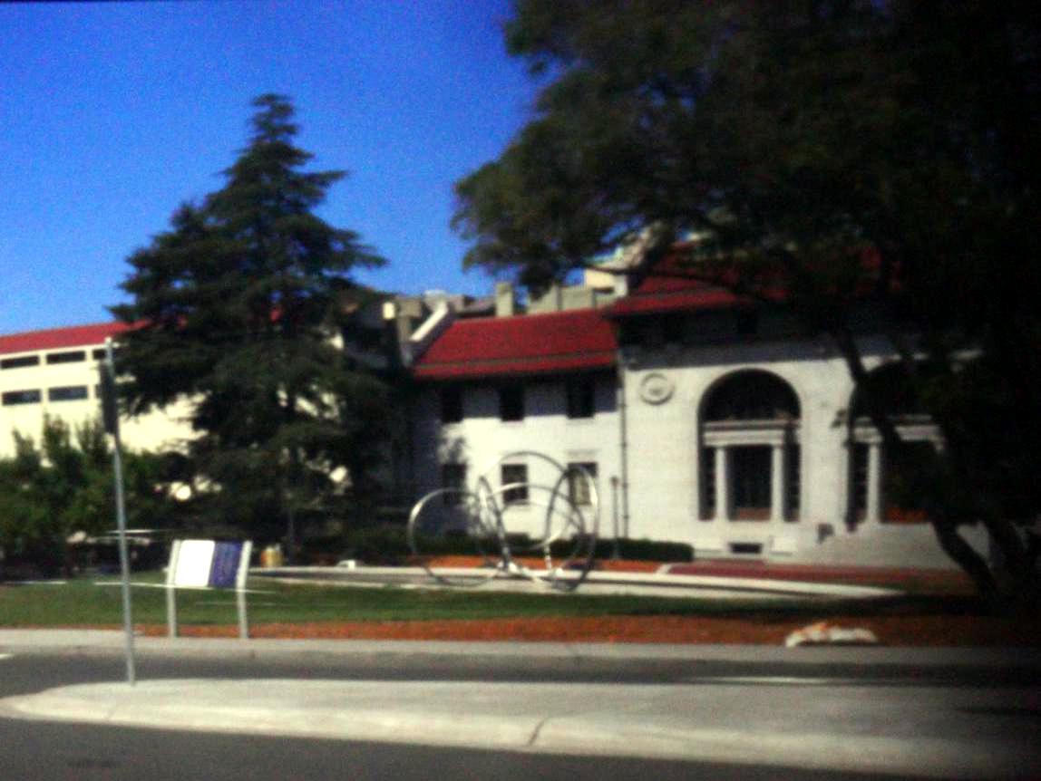
VLSB
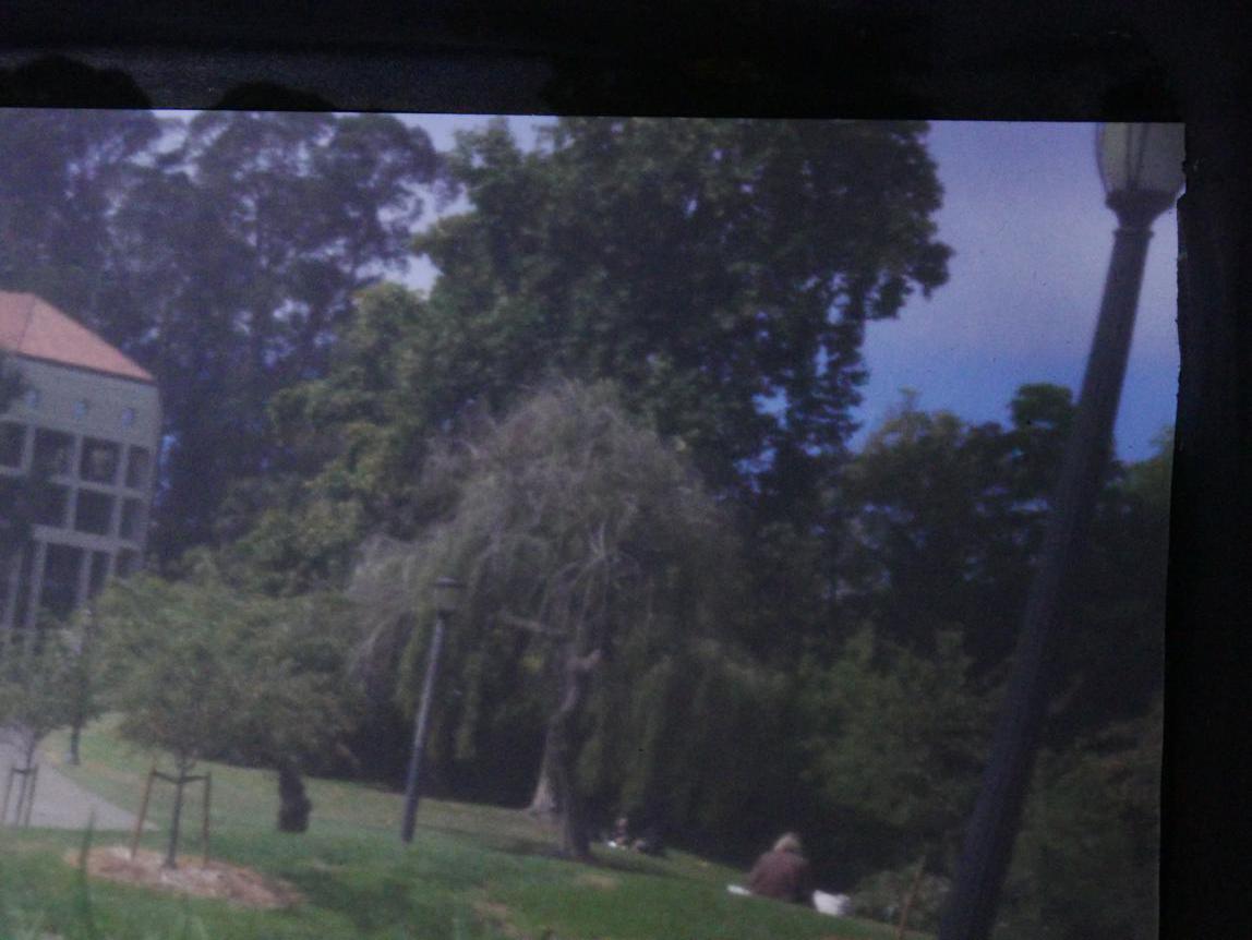
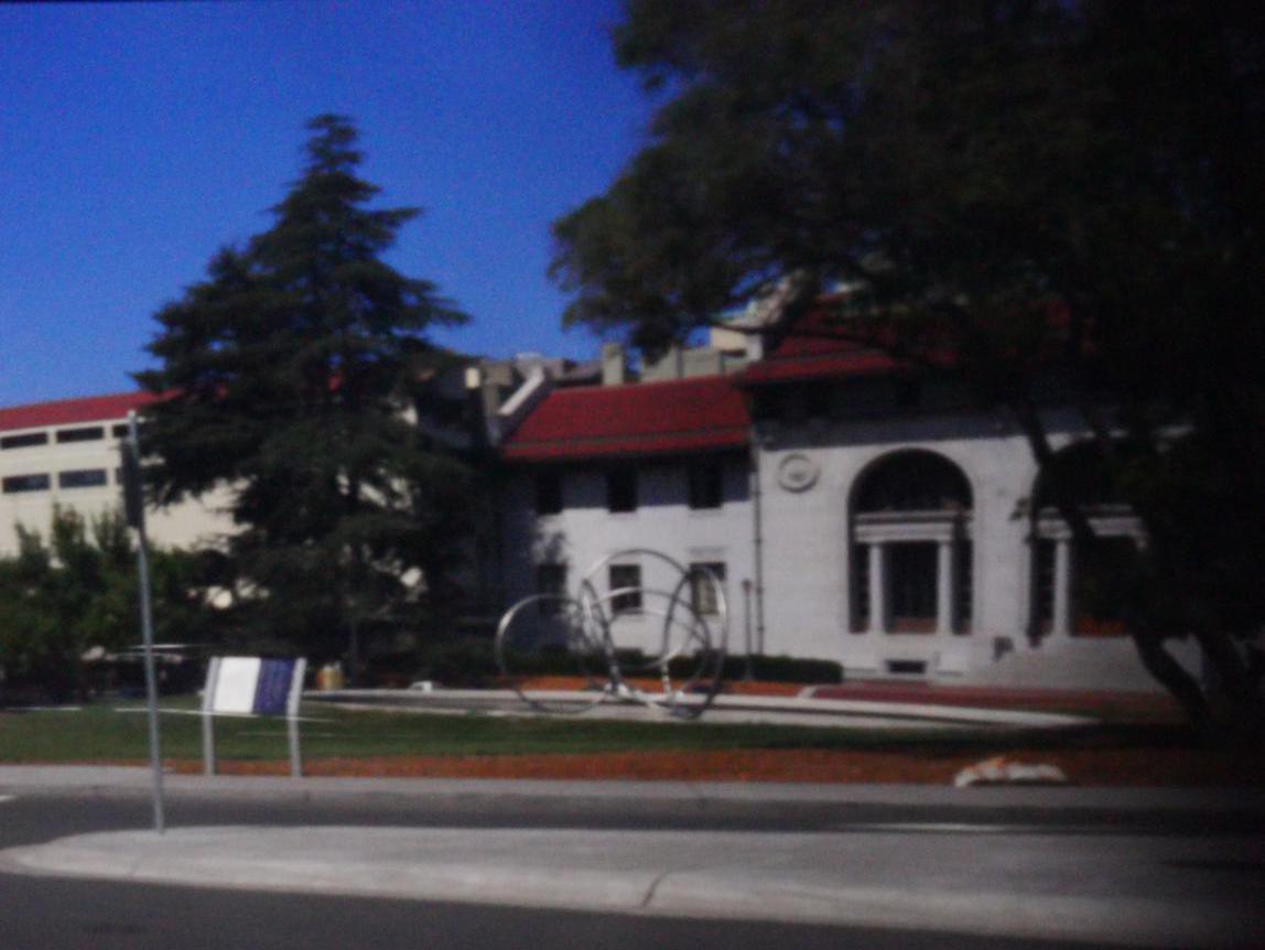
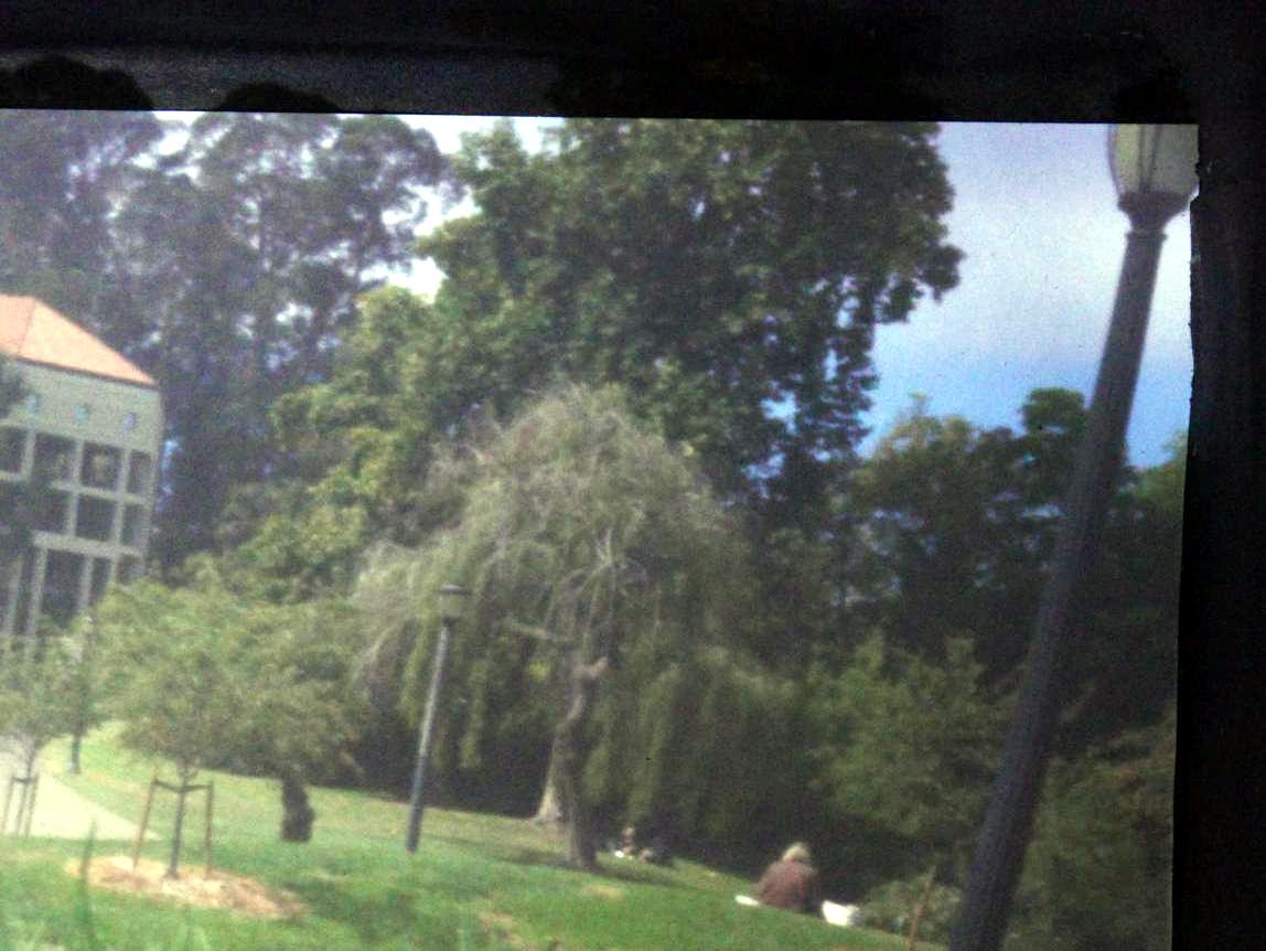
Mulford
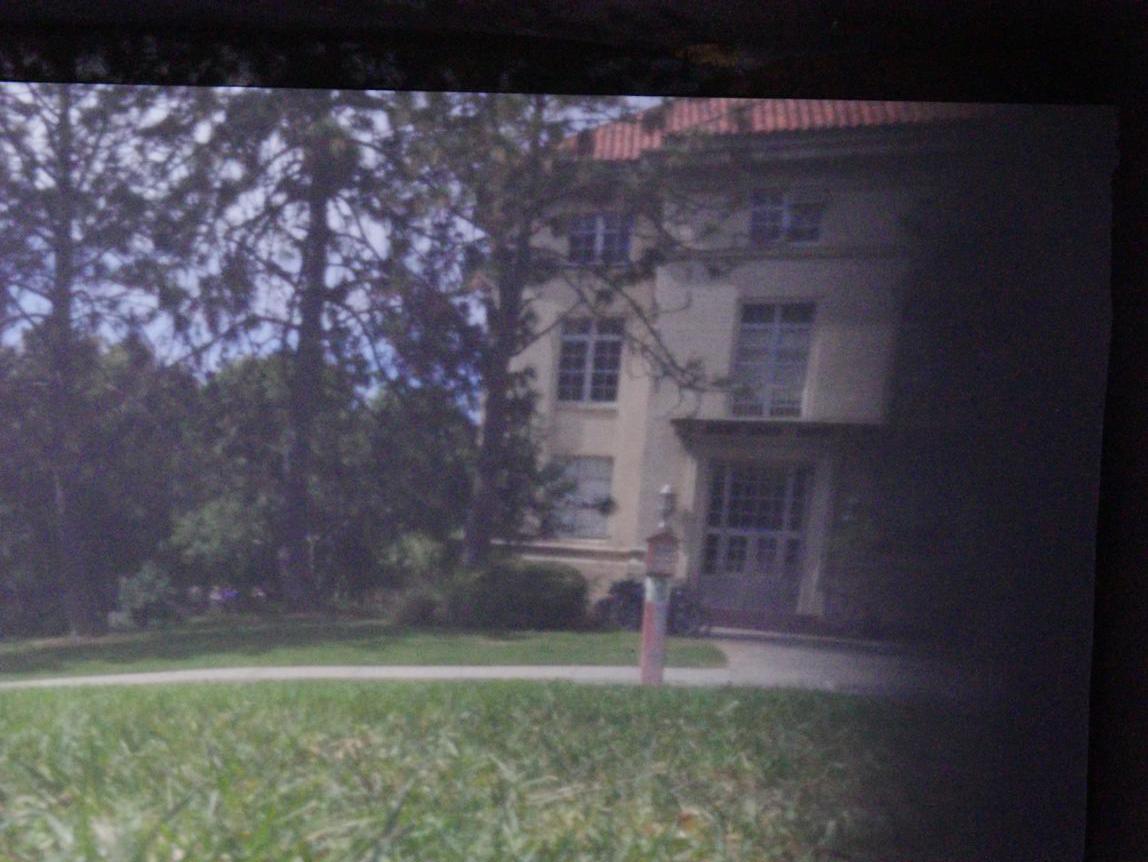
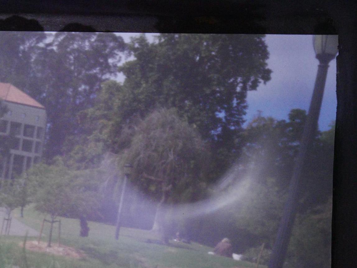
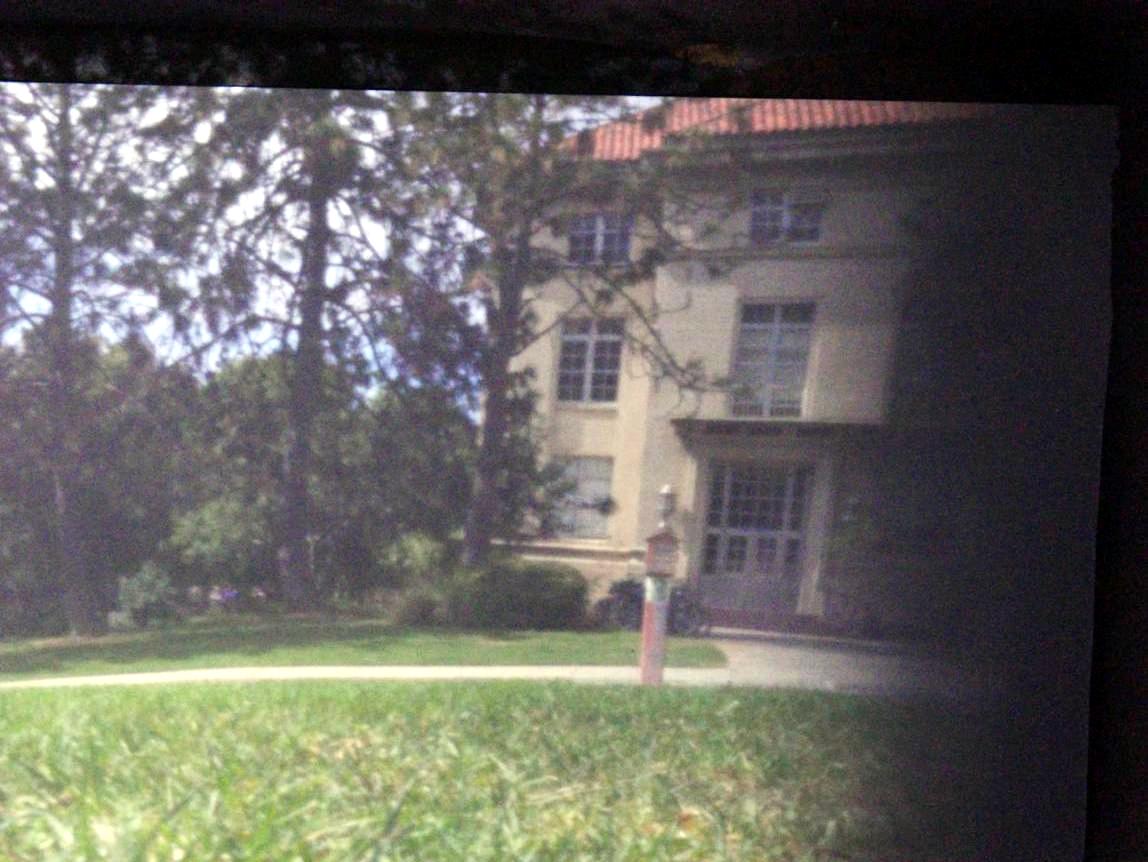
McCone and O'Brien Hall
Hearst Mining Circle
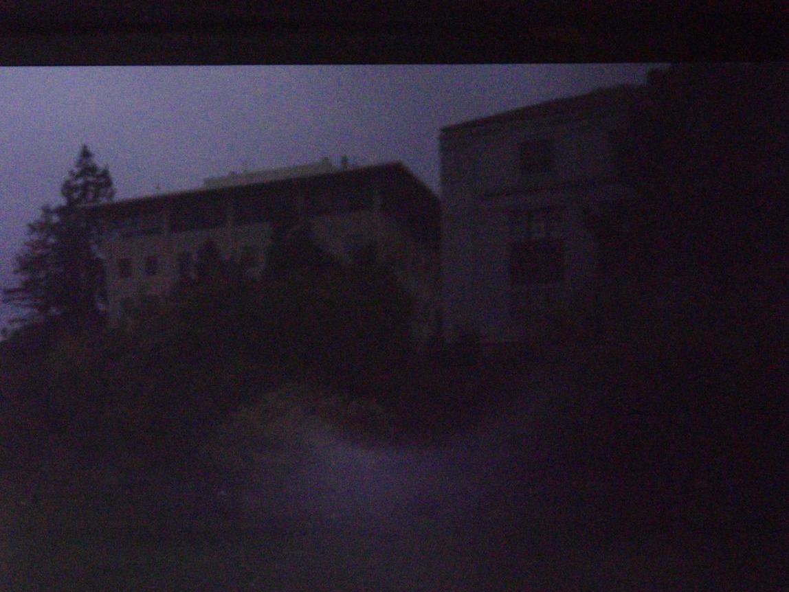
Failures
While taking these photos, we came across several failure cases
that resulted either from mistakes in taking the photos or simply
located in areas with low-light conditions that were not suited
for taking photos.
Light Leakage
This failure was the result of light leaking in from the hole we
made for the camera. We only noticed this issue rather late into
our photo taking particularly because the camera never faced into
the sun until this particular photo, makign the leakage fairly obvious.
The solution was rather simple - lay a sweater or piece of cloth
over the camera when taking the photo.
High ISO
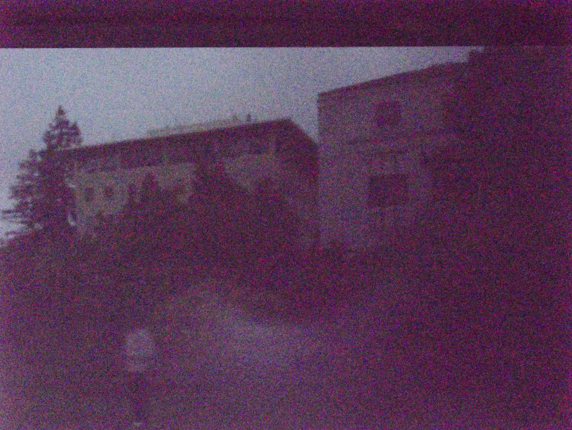
On the cloudy days, we tried to hack together a brighter image by
maxing out the ISO - in this photo we set the ISO to 25600. As you can
see this caused the camera to turn the entire image red and add lots
of noise to the image.
Bells and Whistles
White Balancing and median filtering
In order to make the look more vivid and less noisy, we used the white balancing algorithm from project 1 along with a smoothing median filter to enhance the images. The median filtering seemed not to help unless it was turned on so high that it was destroying image details. The results look like following:
Hearst Mining Circle
VLSB
McCone and O'Brien Hall
Mulford
Light Painting
We decided to dedicate our series of light painted photos to all things Cal.
Cal
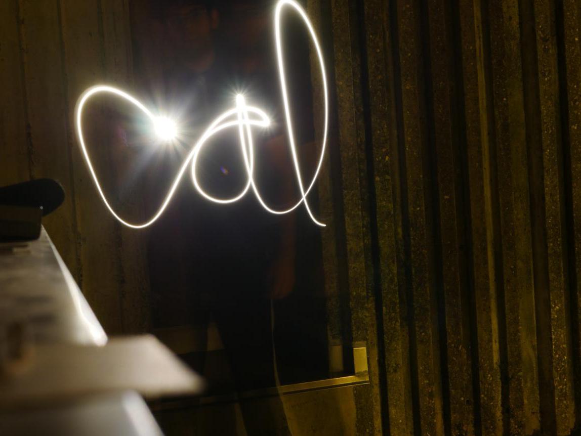
No Cal themed picture collection would be complete without a classic
Cal logo.
LuminOski
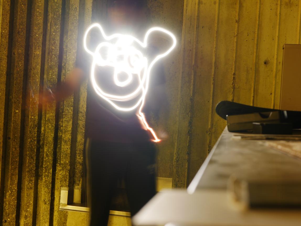
Of course we included the creepy and lovable Oski, emerging in his
new form as LuminOski
Protestor
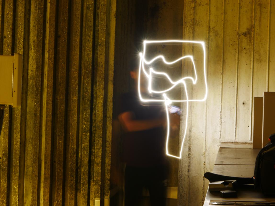
What would a trip through Berkeley be without an avid protestor.
You can almost hear the half-dozen helicopters flying overhead!
Vase
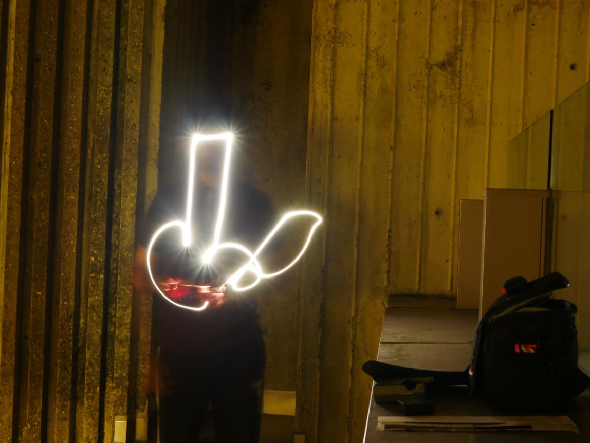
Finally, we can admire this amazing vase!
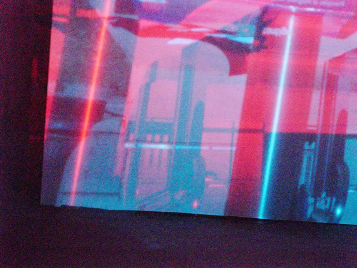
Stereoscopic Pinhole Camera
As an extension of the pinhole camera, we decided to add the functionality to take stereoscopic images.
To fascilitate this end, we added a second aperture to our box design (immediately vertical to the original pinhole)
and used red and cyan filters to take pictures.
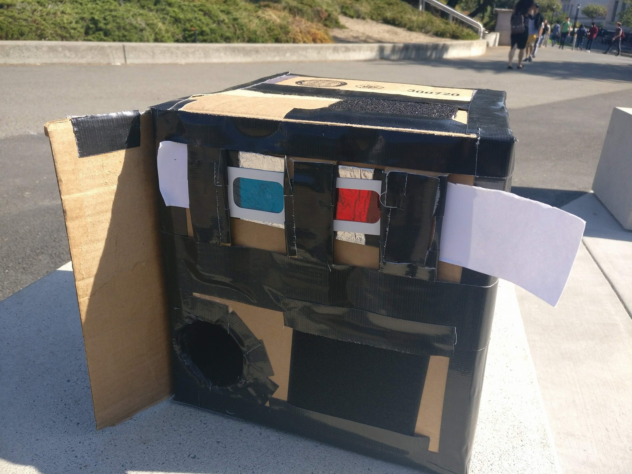
The setup for the Stereoscopic images.
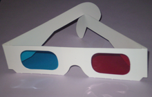
3D glasses for viewing the sterescopic pinhole images
You might remember this sort of technique from ground-breaking movies like Spy-Kids 3D and Shark Boy and Lava Girl. The basic idea is
that you project two different images through a red and cyan filter respectively. The apertures are set slightly apart to allow for stereoscopic
effects, mimicking how the eyes see the world. The resulting image can then be viewed using special 3d glasses with the same filters, as seen in the image above

Art in the most absolute sense.
The results of our tests were mixed. First we ran into the issue where we incorrectly setup our apertures. Originally we set our apertures to be vertical of one another, leading to the image below. This was unsatisfactory because viewing it with the proper glasses would lead you to go cross eyed.
Badly setup stereoscopic image.
We rectified this issue by simply tilting the camera.
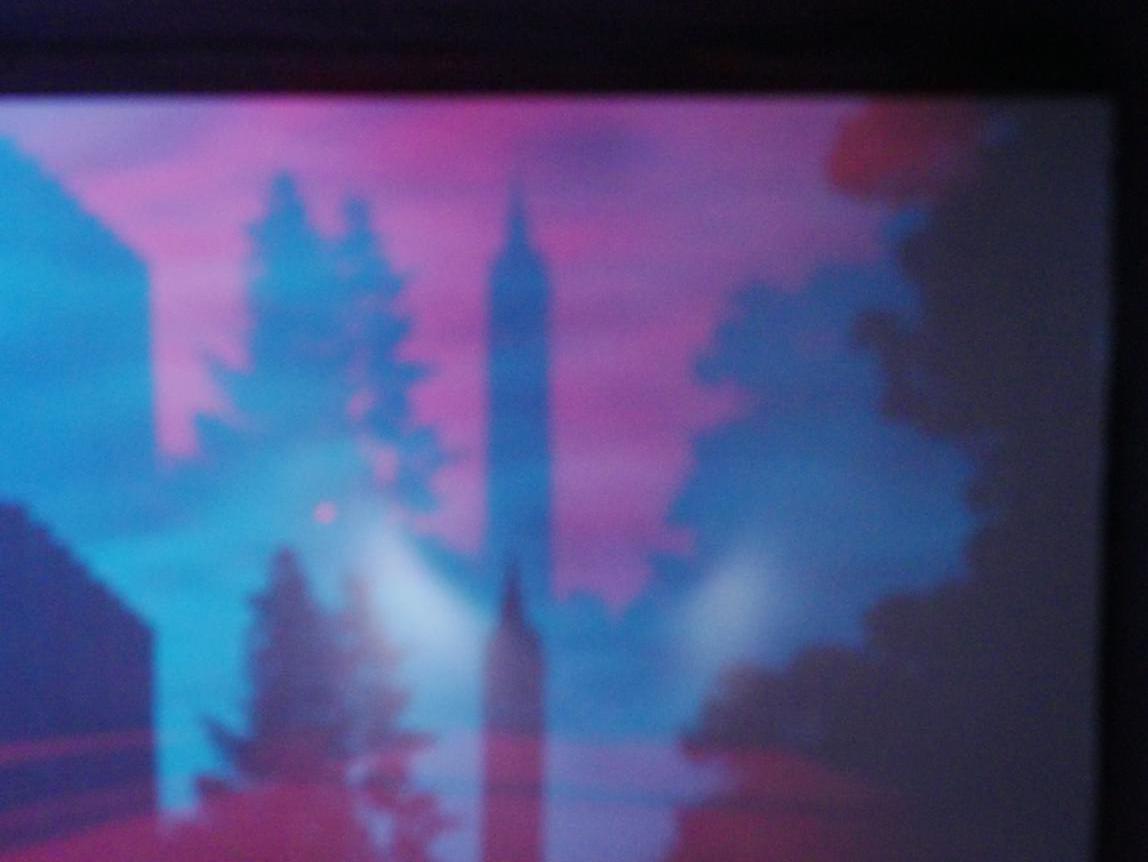
Next we ran into the issue where the projected images were much too far apart. We designed our camera too far ahead of time to
realize that the stereoscopic projections are meant to be right next to one another, instead of attempting to replicate the width.
As a result, we got images like the one below - where the background appears to be shifted far away from the intended direction.
Campanile better stereoscopy orientation - bad alignment
Picture of a tea thermos - still badly aligned
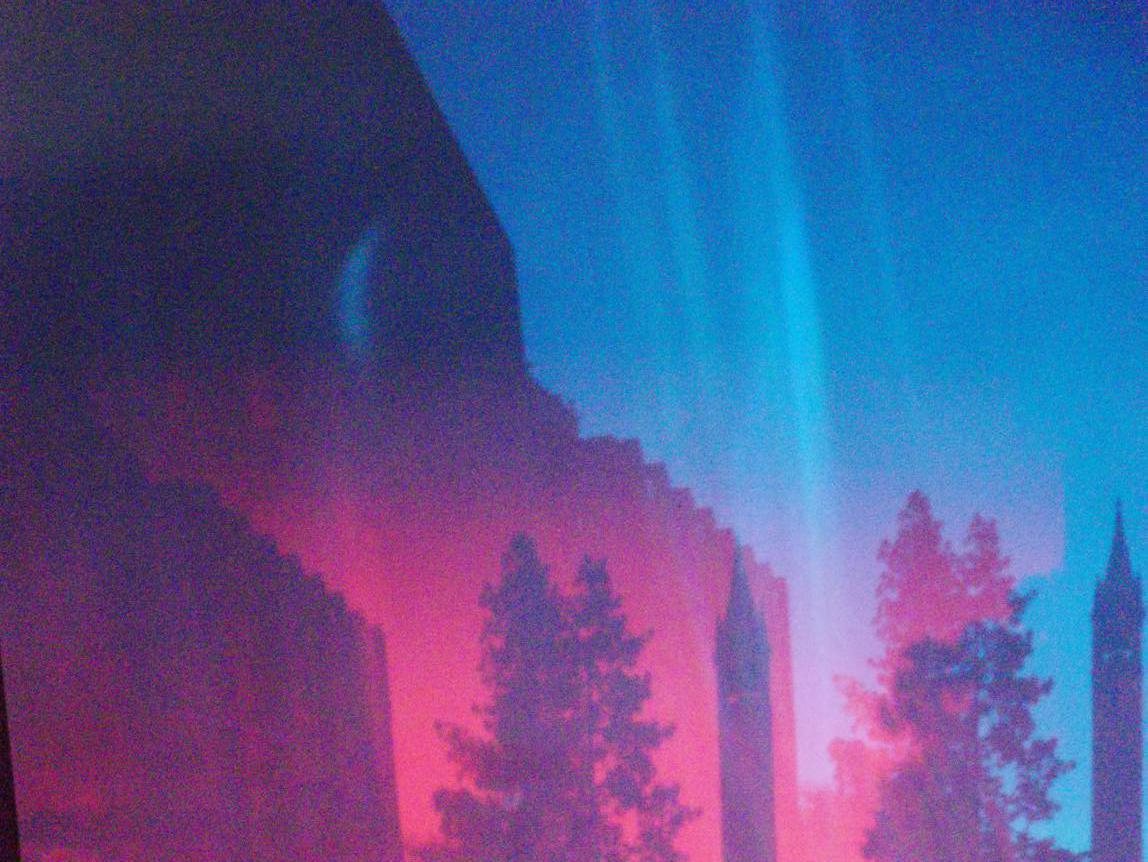
We tried to fix this by realigning using code from project 3, however when viewed through proper glasses, the 3d effect is still not quite there
Realigned image
If we had more time, we would redesign the sterescopic pinholes to put them much closer together to ensure that the field of
view was much better aligned.