Part 1
Recover Homographies
To do image rectification we must first calculate the transformation matrix also known as the homography matrix. This is an 3X3 matrix with 8 degrees of freedom. The last entry is just a scaling factor one. We provide user input for 4 points on one sample image and then 4 points on the other image, that are supposed to correspond to the same approximate square in the previous image. For frontal view rectification we treat our second set of points as (20,20), (110,20), (110,110), (20,110) - a pefect square. We then solve a system of equations with least squares to compute the values of the h matrix.
Image Rectification
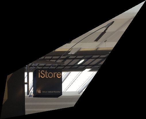
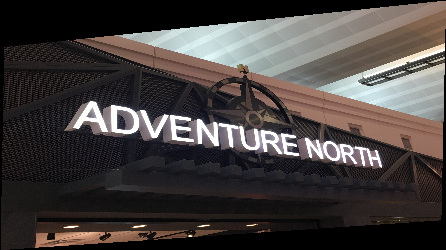
In image recitification we are warping images primarily taken from the side shot, so that they can be seen from a frontal view. To do this we take the image we want to warp and inverse map each pixel to the proper space in a new image. This is done by taking a coordinate on the new image and doing a dot product of this with the homography matrix. The coordinate values that result from this correpond to pixels in our previous image which will now be placed in a new slot in our resulting image. As you can see the sign for the i store warps very well onto a flat frontal plane, while the compass warps onto a frontal plane, but does not do as well because it is not as square of a symbol to work with initially.

|
|

|
|
Image Mosaics
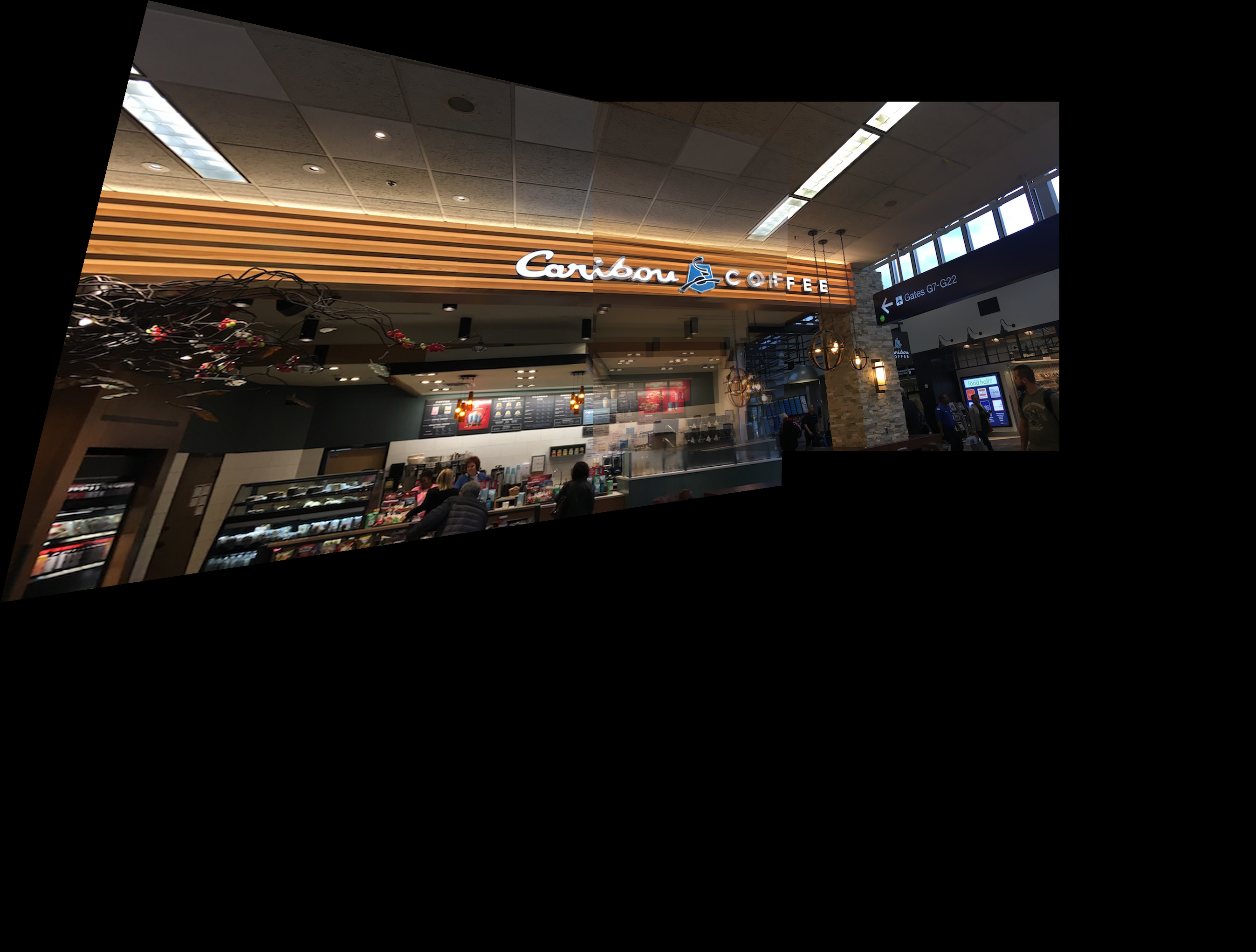
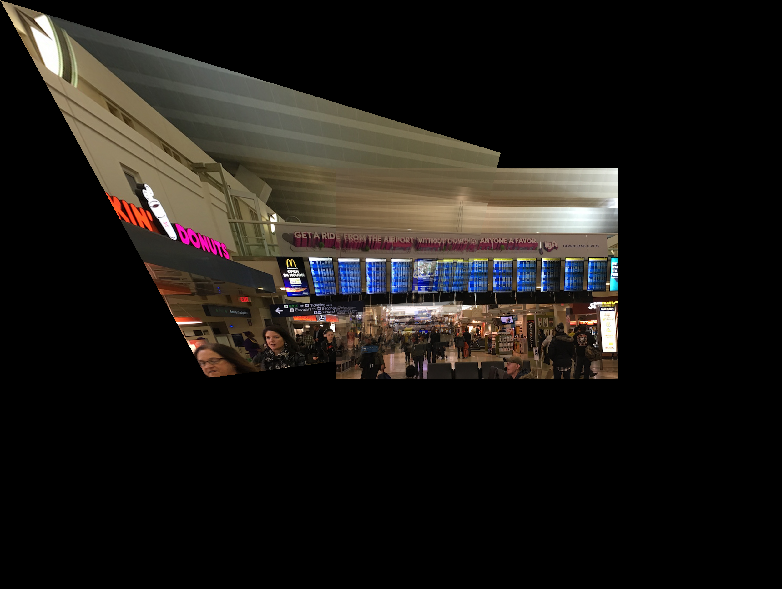
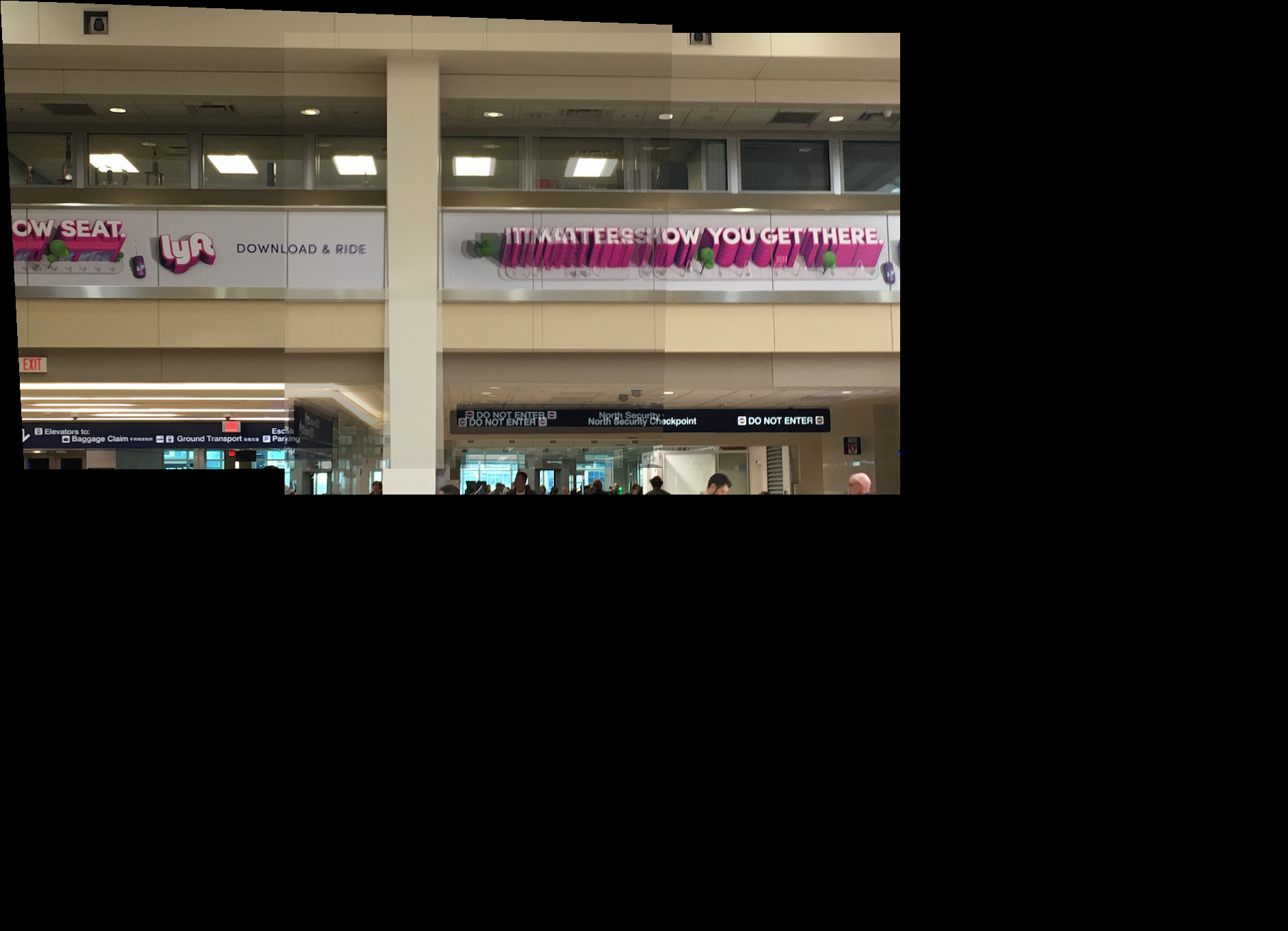
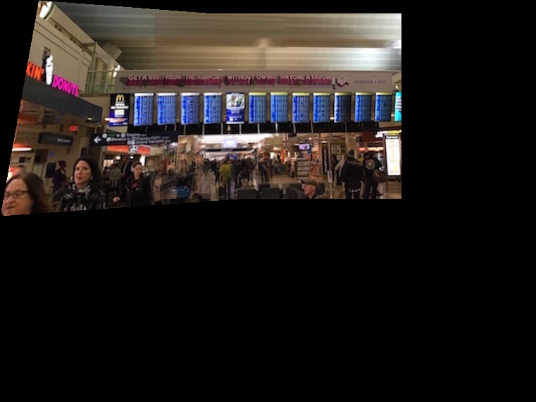
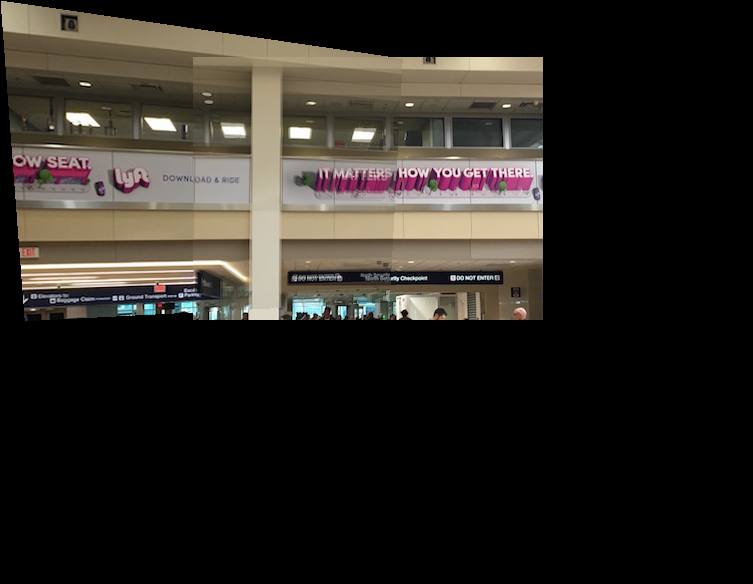
I created an image mosaic by warping a first image to a second image trying to choose my points as a square object that is visible in both images. Then I created a mask for this warped image and the second unchanged image. This was done so that I could see what parts of these images overlap. For the overlapping part I implemented averaging blending, so I multiplied the pixel values of each image by 0.5 and added them together. Then I placed the non-overlaping pixels of both images into the proper place on my new image, again using my mask by seeing what section of each picture don't overlap. This in the end creates a mosaic, panoramic like image. As you can see the caribou coffee and lyft label mosaics worked farily well because they are relatively simple pictures with a decent amount of natural squares in them. The natural squares allowed me to create a clean seem with my warp, and the realtive lack of noise in the image made the mosaic cleaner. The flight board picture had to much noise so the resulting mosaic is hazy. In addition to this the reference square objects for this image are relatively far away making the seem less clean.

|

|
|
|

|

|
|
|

|

|
|
Summary
I learned that one can use linear algebra techniques to artifically alter the view of a picture, and effectively splice multiple images together into a panorama. Note all pictures were taken in Minneapolis–Saint Paul International Airport because I was traveling for interviews.
Part 2
Harris Corners
You get our initial interest points by obtaining harris corners for our images using the get_harris_corner code given to use when starting the project. This involves looking at individual 3X3 windows of the image and finding the pixel with the maximum value for a given harris function in that window.
|
Adaptive Non-Maximal Suppression
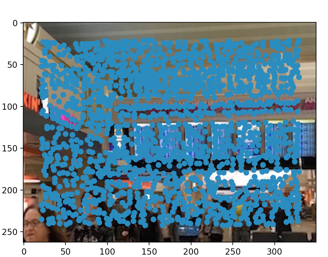
You use ANMS to narrow down a set of interest points, while ensuring that they are well distributed spatially. For each point in our set we find the closest point whose robustness value multiplied by corner strength is greater than our initial points robustness value. You gather the mininal supression r-value for each point and I picked the top 500 points.
|
Extraction and Feature Matching
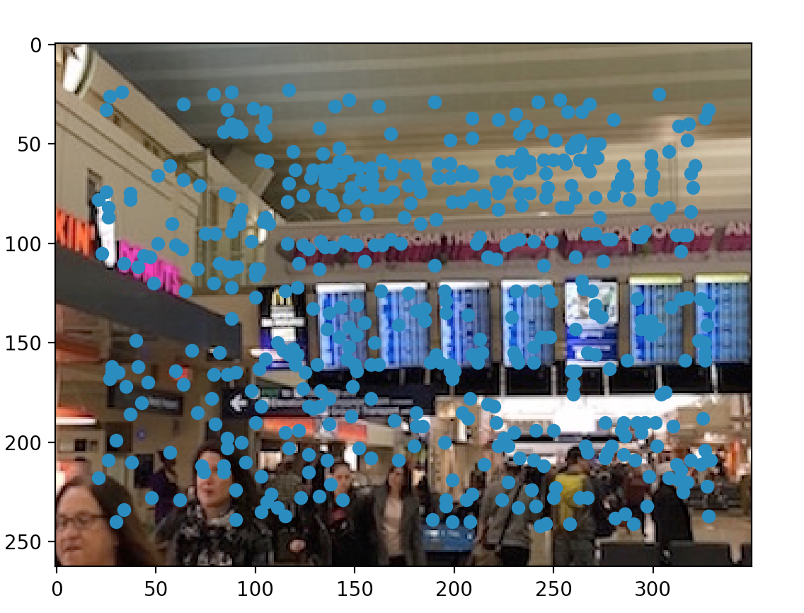
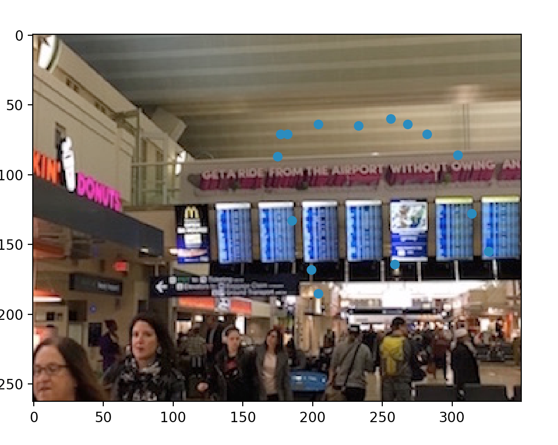
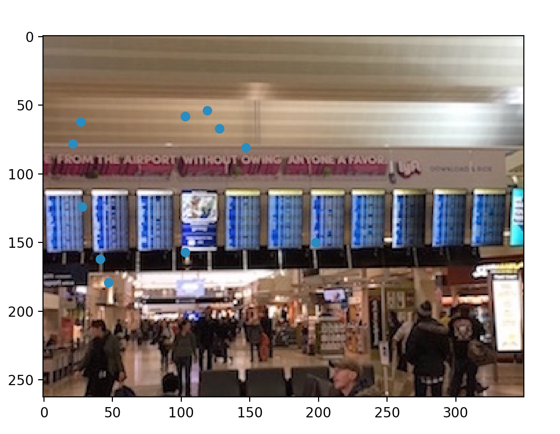
The last form of narrowing down points of interest is to only choose feature points that map between two images. You represent each point and the 40x40pixel around it as an 8x8 re-sized image. In the matching process for every point of interest left in our first image using SSD we find the best and second best matching point in the second image. For my personal function if the first_match/second_match < .35 then I kept the feature points as matching feature points. As you can see in the images below there is a semi circle of points that match around the words "From The Airport Without" on the above banner, and there is a significant matching point right under the center monitor.
|
|
RANSAC
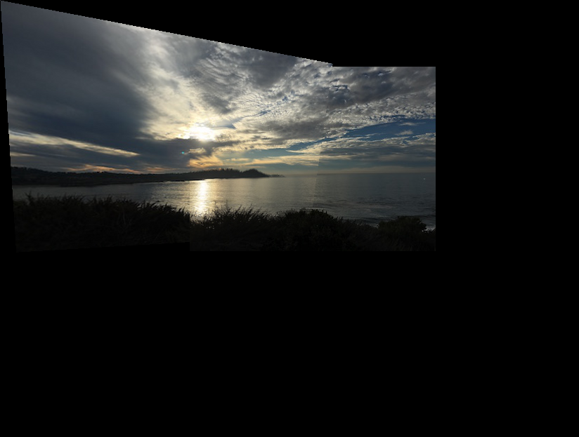
For RANSAC randomly select four pairs of points from our remaining matching points to compute a homography matrix like in partA. Then you find all inliers for that homography matrix which are when a warped point in image 1 that relative to SSD is within some threshold of closeness to the real point in the other image. We run this for 1000 iterations and at the end we take the largest set of inliers and use it for a final homography matrix which is used to complete mosaics of our images. As you can see the mosaics produced by this automated alignment are far better aligned and less skewed than the mosaics produced by manual alignment in part A. This is especially apparent if you look at the board mosaic pictures. I was also able to make a mosaic picture of the carmel beach ocean scene that I was unable to do with manual alignment.
|
|
|
Summary
I learned that automatic feature alignment is far more effective for creating panoramic image mosaics than manual alignment. Even if you pick points that seem to perfectly correspond across two images, the automatic alignment seems like it will most likely be better.