Project 1: Images of the Russian Empire
Franklin Heng, cs194-26-aaw
I. Project Background: Selfies in the 1900's?
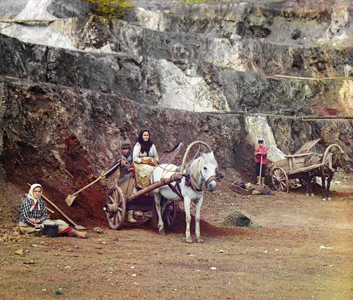
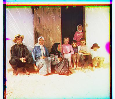
Everyday, when we wake up, we are deeply integrated into a society that has been significantly influenced by social media and entertainment - no matter what profession or educational background we hold. Fundamentally, we are all able to express our thoughts and perceive all this information because of highly innovative cameras that allow us to capture any moment in a matter of seconds. Soon enough, we will literally be experiencing each others past events (VR and Haptic Feedback!). But, do you ever wonder, how were things being captured in the 1900's? Lets use the image above as an example, after that shot, did they all crowd together with a selfie stick and hashtag 'sqaud goals' and 'chillin with my horse'? Probably not.
In fact, the photo taker had to slide a glass plate into his camera and snap the photo three times, with each shot representing the R, G, and B channel, just to properly capture one scene. The man who captured the photo above was Sergei Mikhailovich Prokudin-Gorskii. Although this technology seems (and is) very outdated, capturing color photos using his technique was revolutionary at the time. It was so revolutionary, that he received permission from Tzar to travel across the Russian Empire to take photos of various building, plants, and people.
Now, given three different photos, how does one combine them to create a single colored image? In the following sections below, I will explain how we utilized digital image processing techniques to generate colored images from three different image channels.
II. Image Alignment Algorithm: Lets Keep It Simple
First, lets start with the simple approach. The following steps below outlines the naive steps I took in order to take three photos (each representing R, G, and B), and stack them on top of each other in a way that it creates one clean, colored photo.
- Usually, three images are put together in one photo. Since they are equal sizes, we just split the photos height by 3, and extract each photo individually.
- Since the photos usually have weird borders on the edges, we just manually tok off 20% of the image on all four sides.
- We take one of the channels as the reference channel and compare against the other two channels. Since the blue channel was very bright, we just arbitrarily picked the green channel to be reference.
- Now, for both the green and red channel images, we have to find the best allignment against the green image channel. The two mathematical metrics that are traditionally used are Sum Squared Difference (SSD) or Normalized Cross Correllation (NCC). I used NCC - because it sounds cooler. $$NCC = {image1 \over ||image1||} \bullet {image2 \over ||image2||}$$ $$SSD = {\sum \sum (image1 - image2)^2 }$$ To find the best alignment against the reference image, we took the comparing image (blue and red), and shifted in the x, y direction with a displacement of [-15:15]. For every displacement shift, we computed the NCC, and shifted the image based on the direction/displacement that gave the max NCC value.
- Lastly, once we have the best alignments, we stack them together. The final result is then a color photo!
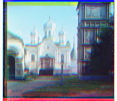
III. Examples: Using the Simple Aproach
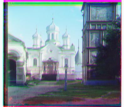
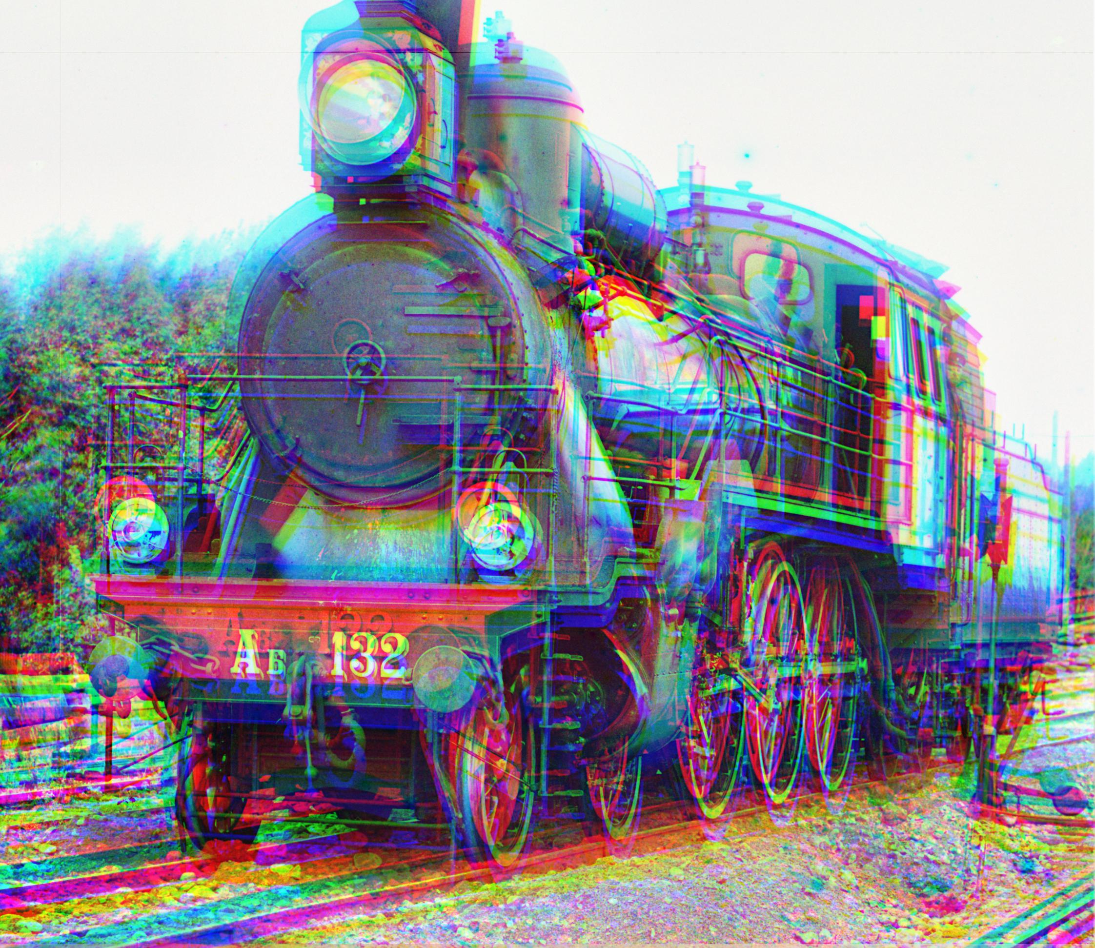
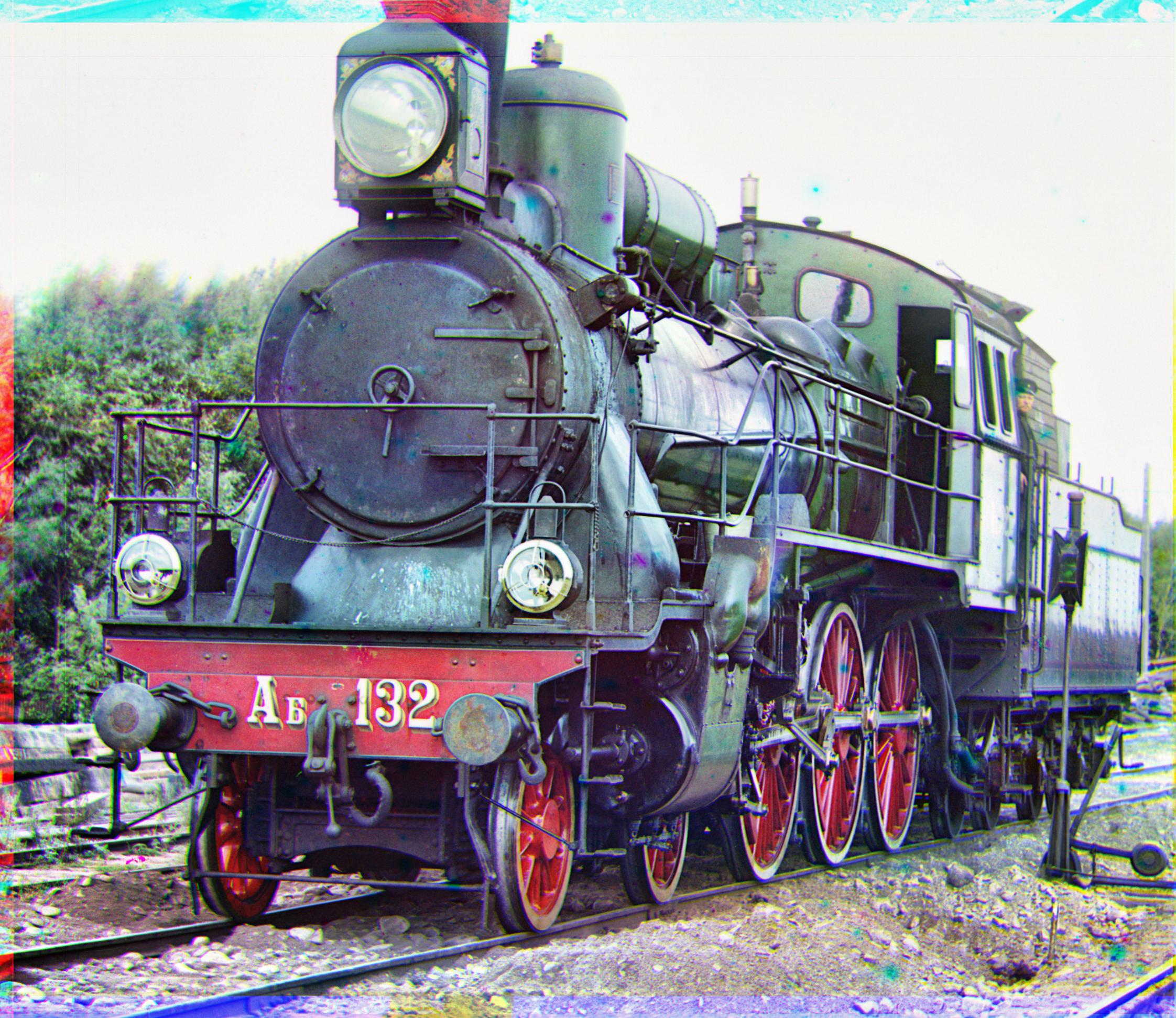
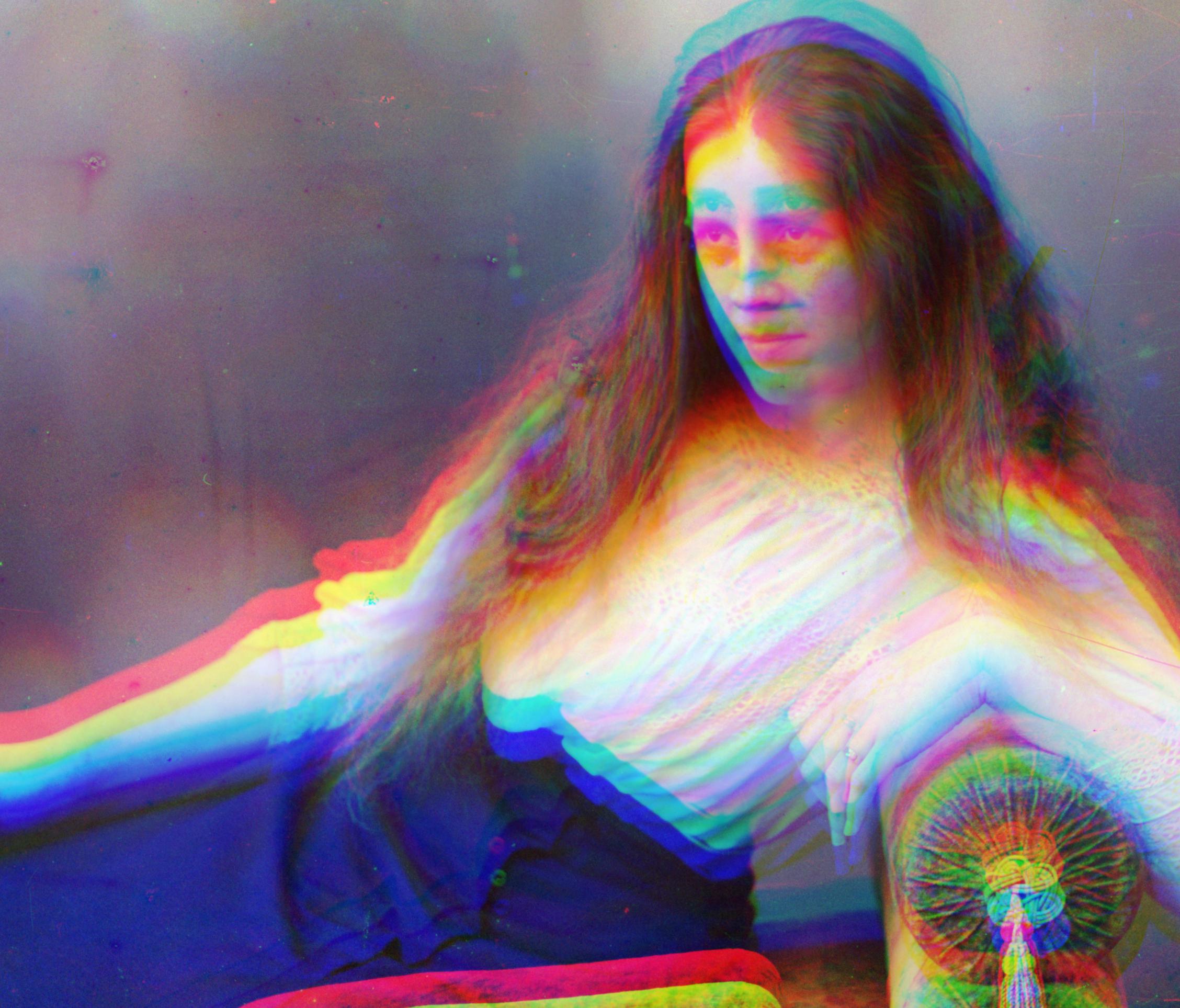
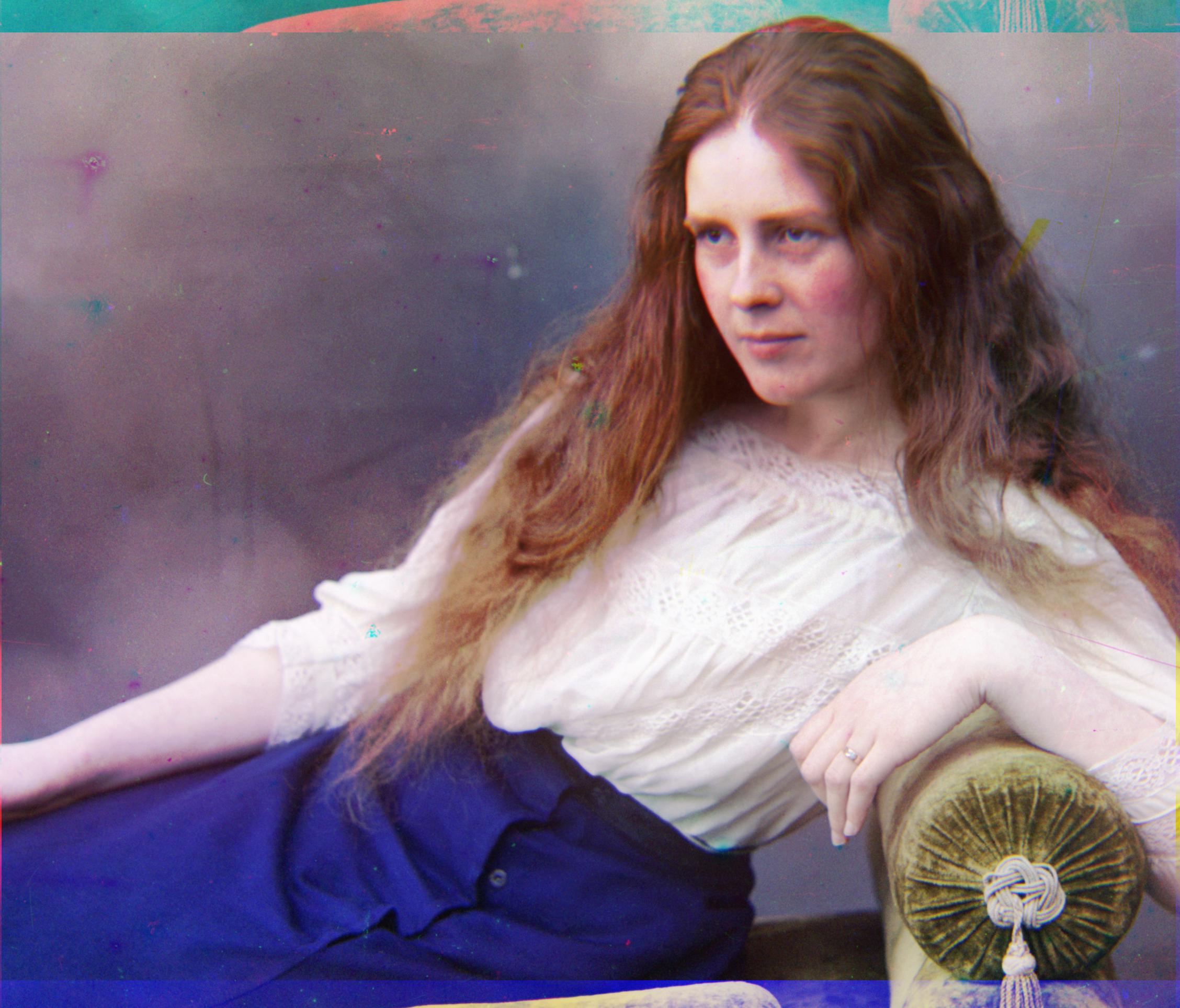
| Without Alignment | After Alignment |
|---|---|
 |
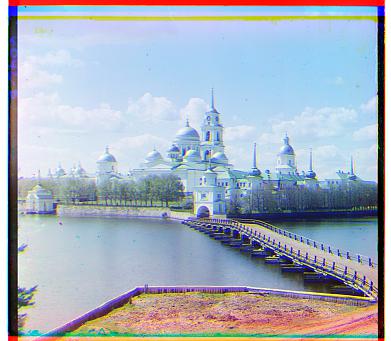
Green: (0, -6), Red: (0, -8) |
 |
Green: (0, -1), Red: (0, -8) |
 |
Green: (0, -7), Red: (0, -14) |
 |
Green: (0, -3), Red: (0, -7) |
|
Green: (0, -1), Red: (0, -8) |
IV. Image Pyramid: Unfortunately, The Simple Algorithm Is Not Enough!
Based on the results above, the naive approach works pretty well. However, if we have a large .tif file (over 3000 x 3000 pixels in size) the naive approach takes a long time! Therefore, we introduce the image pyramid. Below is a visual demonstration of one.
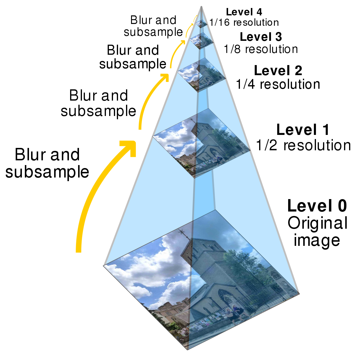
As shown in the illustration, an image pyramid is a structural term used to represent downsizing an image multiple times. By doing this, we can compute an accurate estimate of the displacement on the smallest image, and use it for the rest of the pyramid levels until we reach the original image size. The following below outlines how we used the pyramid algorithm:
- We created an image pyramid, with constant factor of .5 on each level.
- Starting with the smallest image size, we pass it into the alignment function, with an initial search range of [-15:15].
- Once we obtained the shift direction and displacement that was associated with the largest NCC value, we grab the next image in the pyramid, and shift it by the computed displacement * 2 (since each level was rescaled by .5)
- Then we pass the modified image into the equation recursively, however this time with a search range of [-5:5], and repeat the steps until we reach the last pyramid level (original image size).
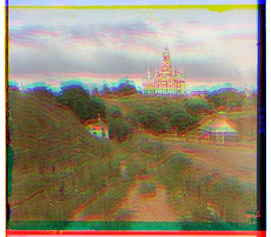
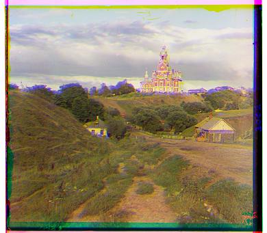
V. Some Examples: Using the Image Pyramid Algorithm
Note: all the images below include all optimizations (color contrast, cropping, edge gradient)
| Without Alignment | After Pryamid Level Alignment |
|---|---|
 |
Blue: (-5, 42), Red: (26, -43) |
Blue: (-14, 40), Red: (5, -48) |
|
 |
Blue: (-8, 53), Red: (3, -62) |
VI. More Optimizations (Extra Credit)
1. Gradient Feature Metric
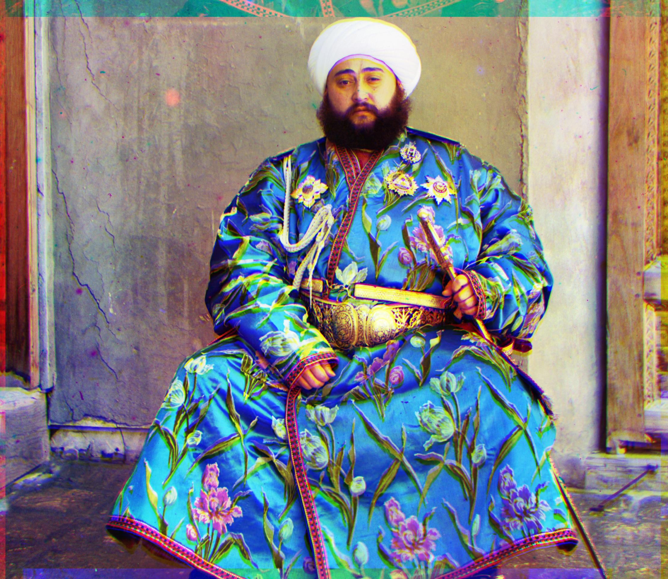
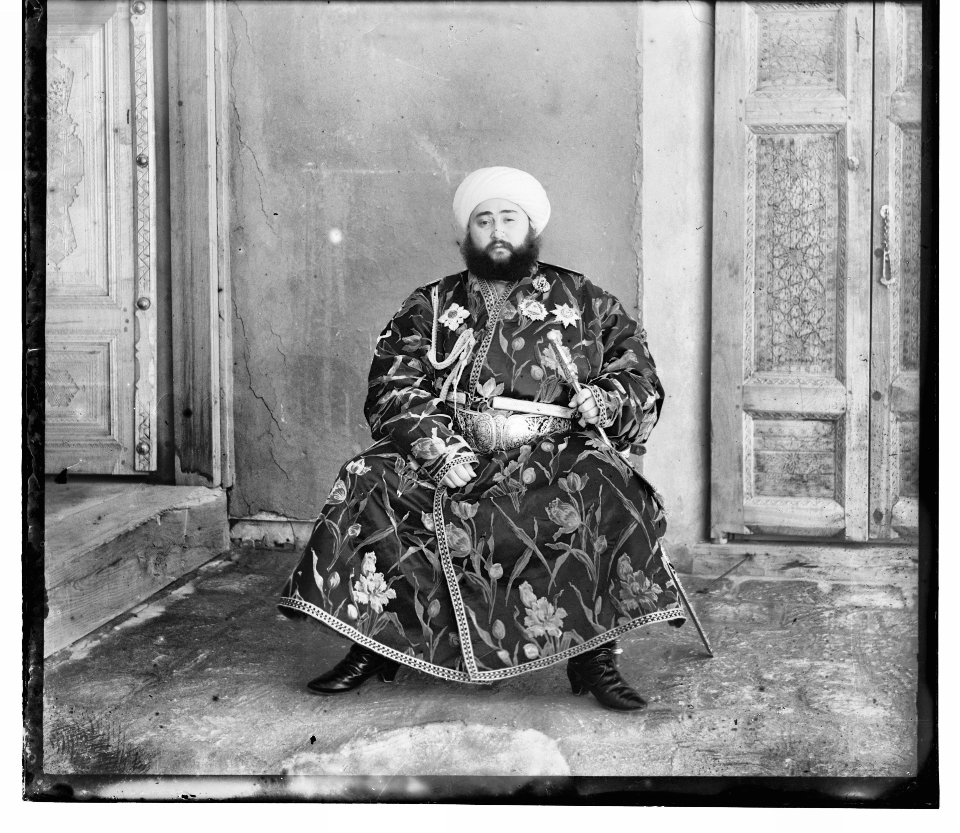
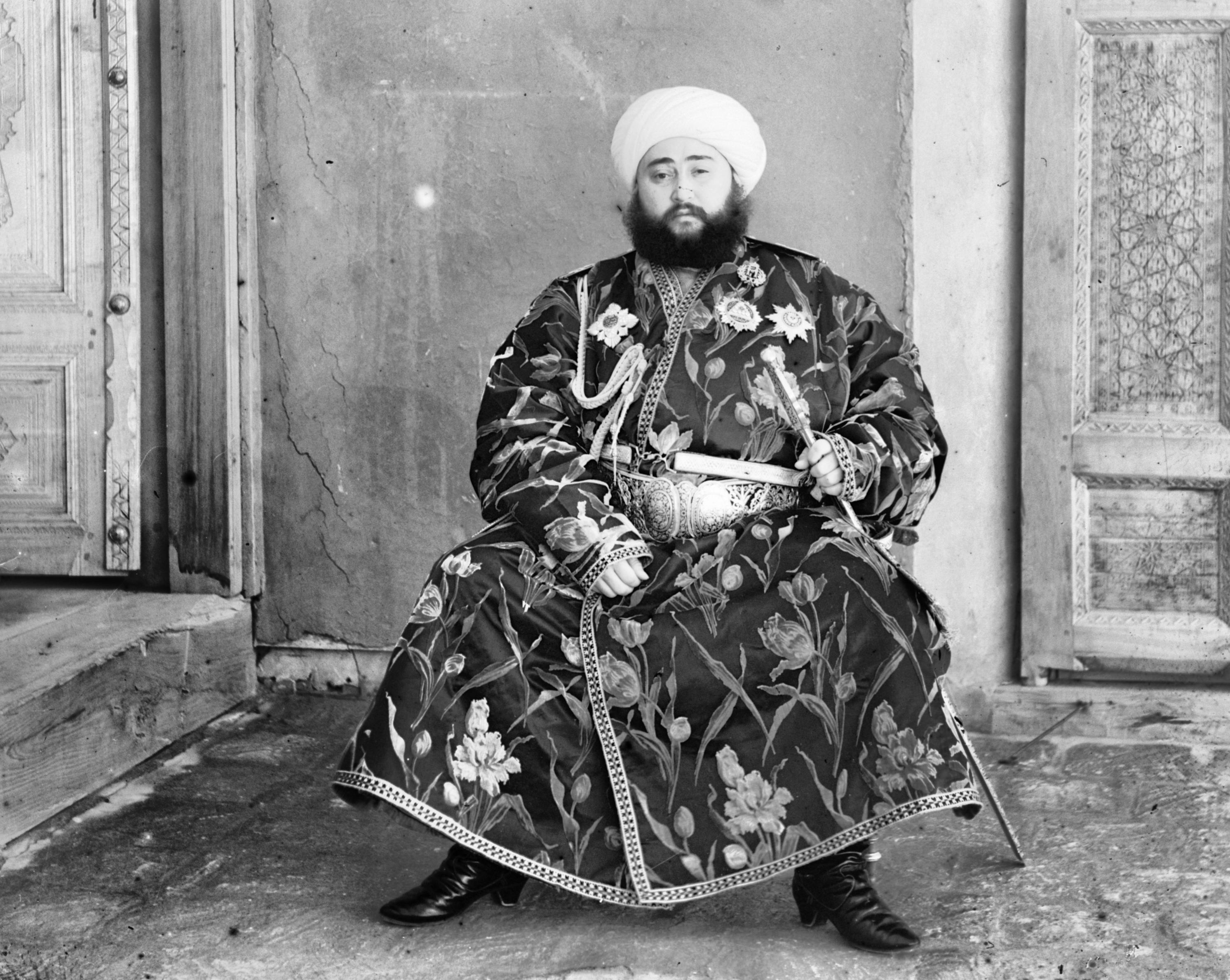
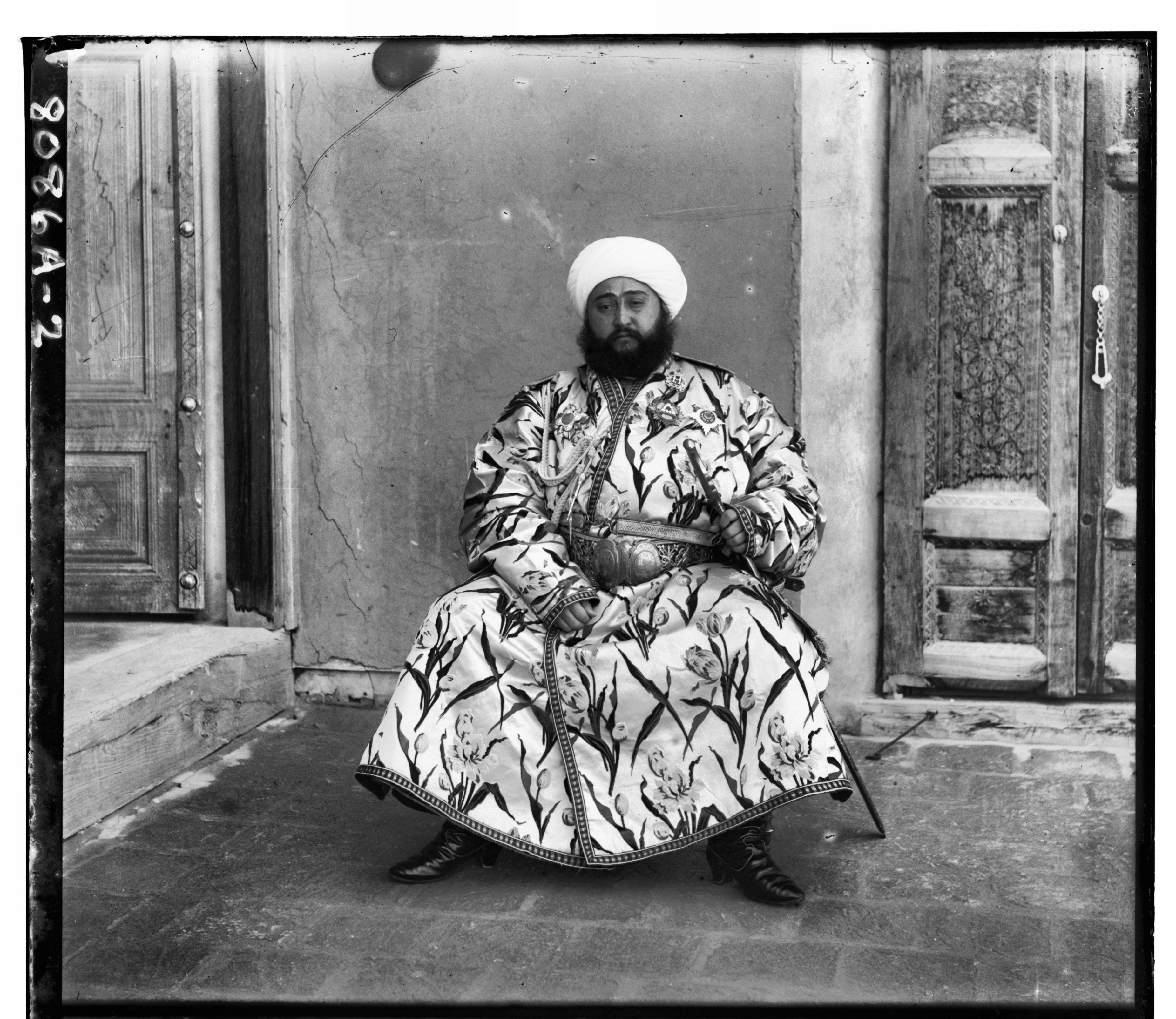
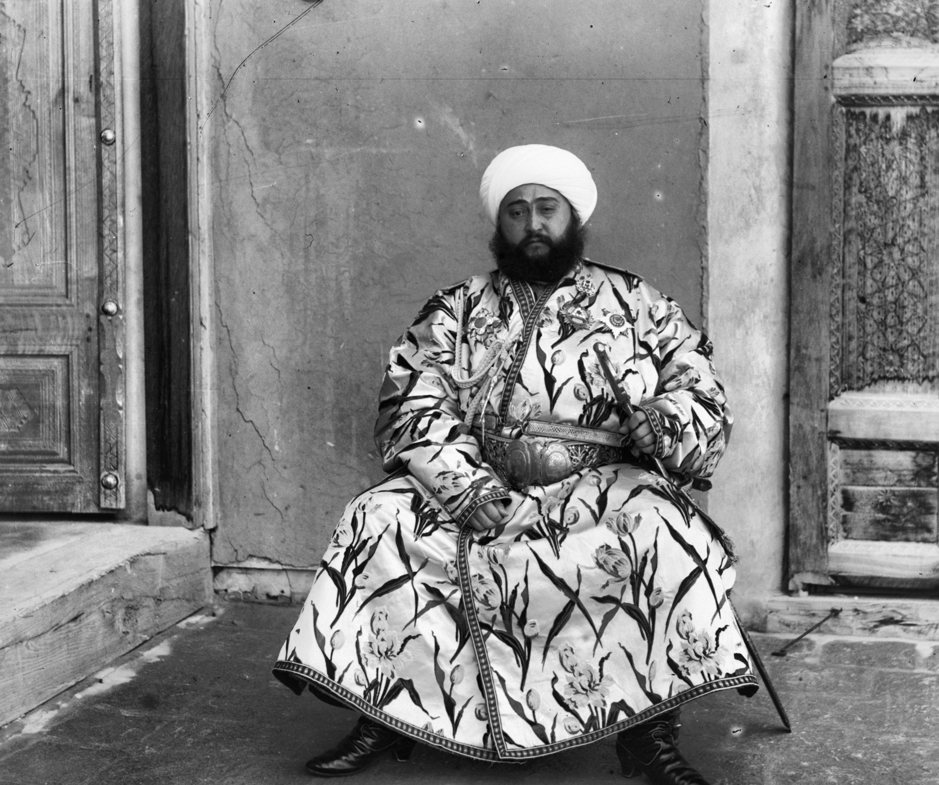
On some images, such as emir.tif, using the pixel values as the alignment metric was not enough. Since the varying brightnesses in the image channels can disrupt the accuracy of the alignment algorithm, using the images gradients significatly improved results. In order to do this, we applied roberts edge operator the images in each pyramid level and added the NCC value to the NCC value computed in pixel metric.
Below is a comparison between emir.tif without gradient metric and with gradient metric. On the left image, there is a subtle blur on the face that is caused by slight misallignment of image channels. After adding the gradient metric, the images aligned more neatly and the overall image is clearer.
| Before Adding Gradient Metric | After Adding Gradient Metric |
|---|---|
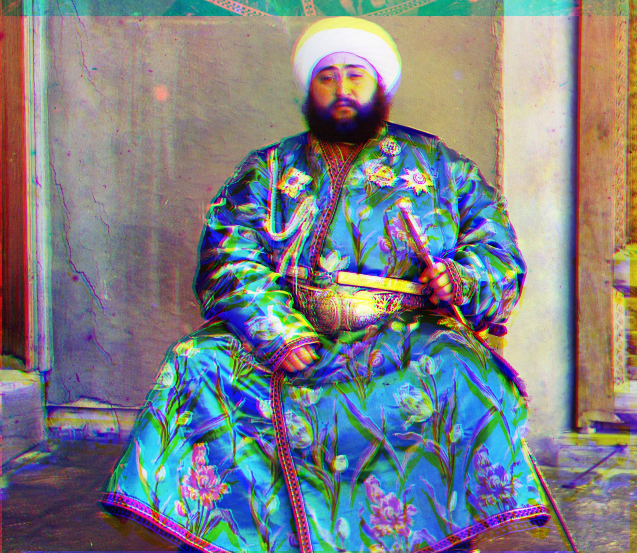 |
Blue: (-24, 32), Red: (18, -57) |
2. Automatic Color Contrasting
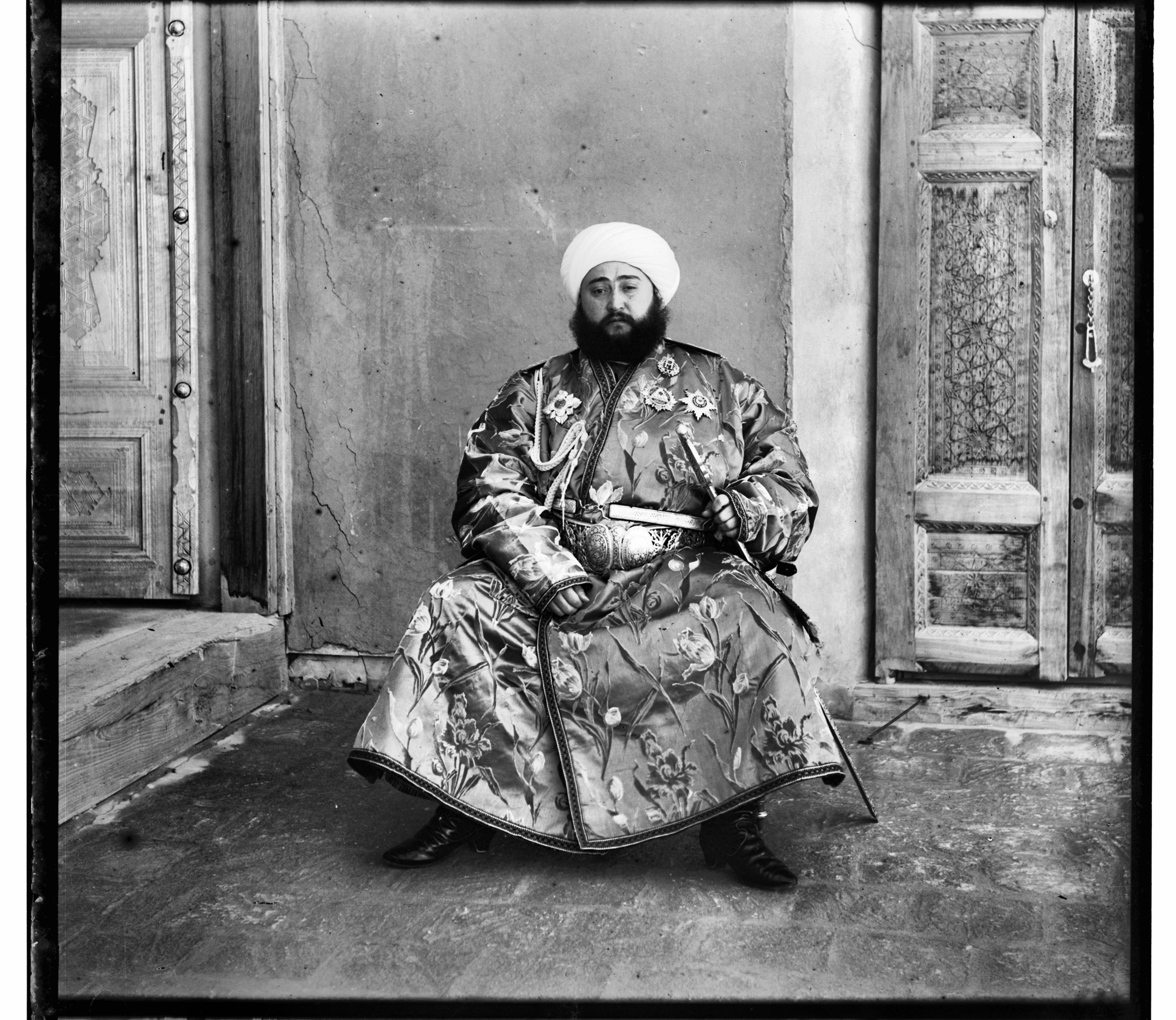
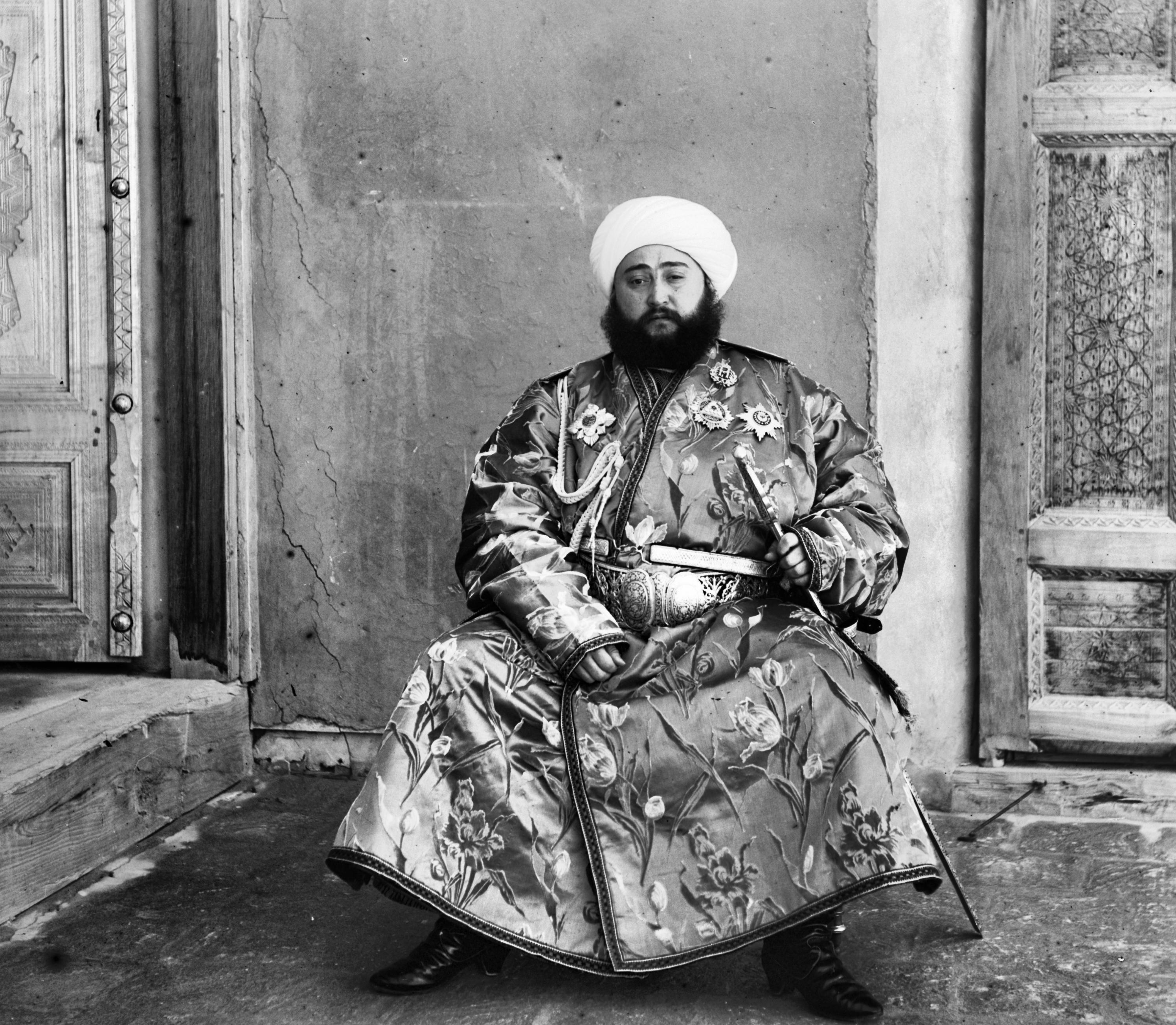
Color contrasting exposes many features and edges within the image by artificially emphasizing the constrast between the light and dark pixels. In order to accomplish this, I iterated through the image and made the brightest pixels white and the lowest pixel values black.
The image below compares the subtle differences between color contrasting and non color contrasting. Without color contrasting, the whole image is much lighter. For example if you compare the faces, you can see that the faces appear much whiter without color contrasting. On the other hand, with color contrasting the color seem to be more enhanced and exposed.
| Before Color Contrasting | After Color Contrasting |
|---|---|
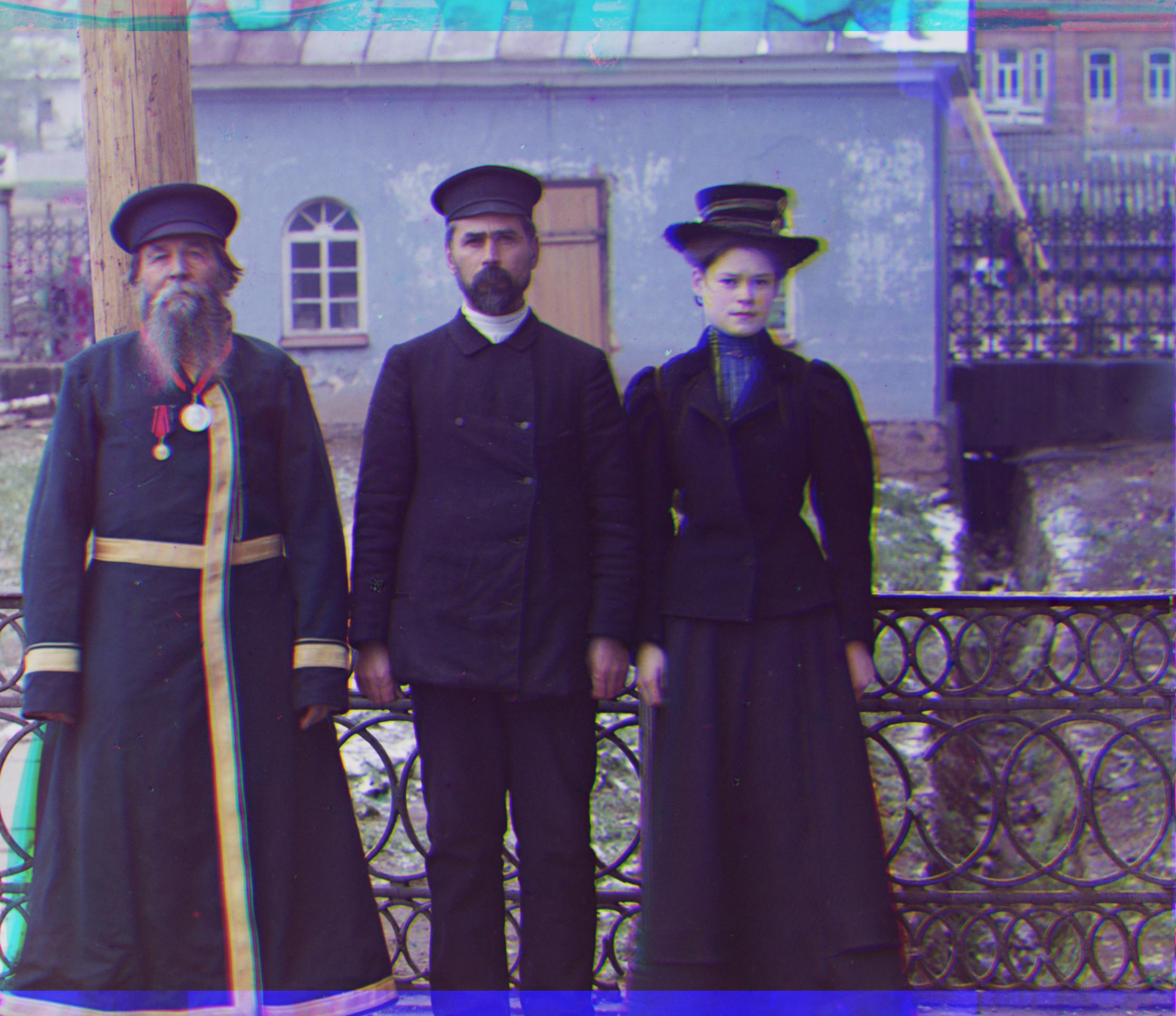 |
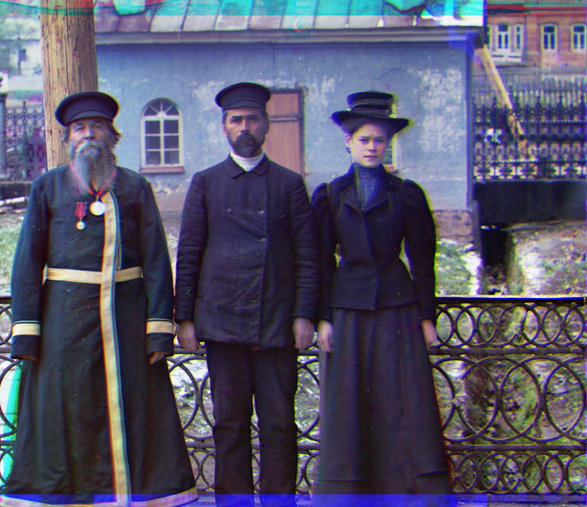
Blue: (-14, 52), Red: (-4, -59) |
3. Automatic Edge Cropping
Personally, this task gave me the most problems. Mainly because each image channel had to be cropped differently, thus creating different image sizes. In order to make the images the same size, I would have to resize the images, which ultimately effected the quality, and significantly hurt the alignment accuracy. Therefore, I left this out from my code.
In order to detect the border, I utilized canny edge detection. I would obtain the distance between each side and the closest edge detected, and remove that distance. After repeating this process for a few iterations, the borders would be removed. Below shows a result for each channel of emir.tif:
| Before Cropping | After Cropping |
|---|---|
 |
 |
 |
 |
 |
 |
VII. More Results
The following images below are results of images that were provided in the project files but I did not show in the examples above. In addition, I also used images that I found off the internet.
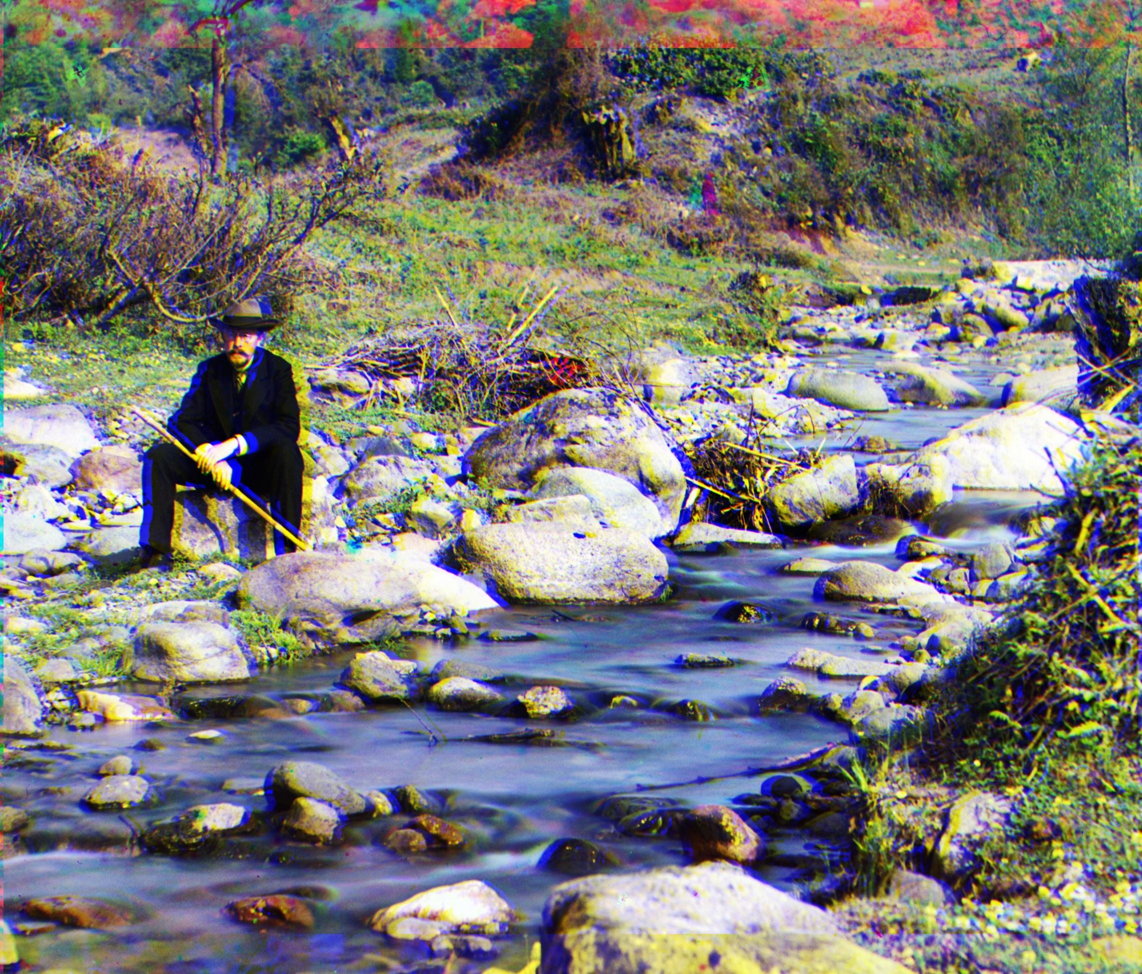
Self Portrait
Blue: (-29, 78), Red: (8, -98)

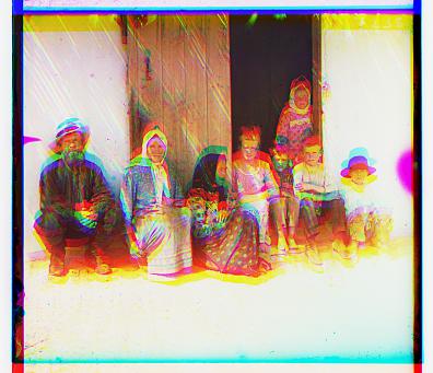
Turkmen
Blue: (-21, 56), Red: (7, -60)
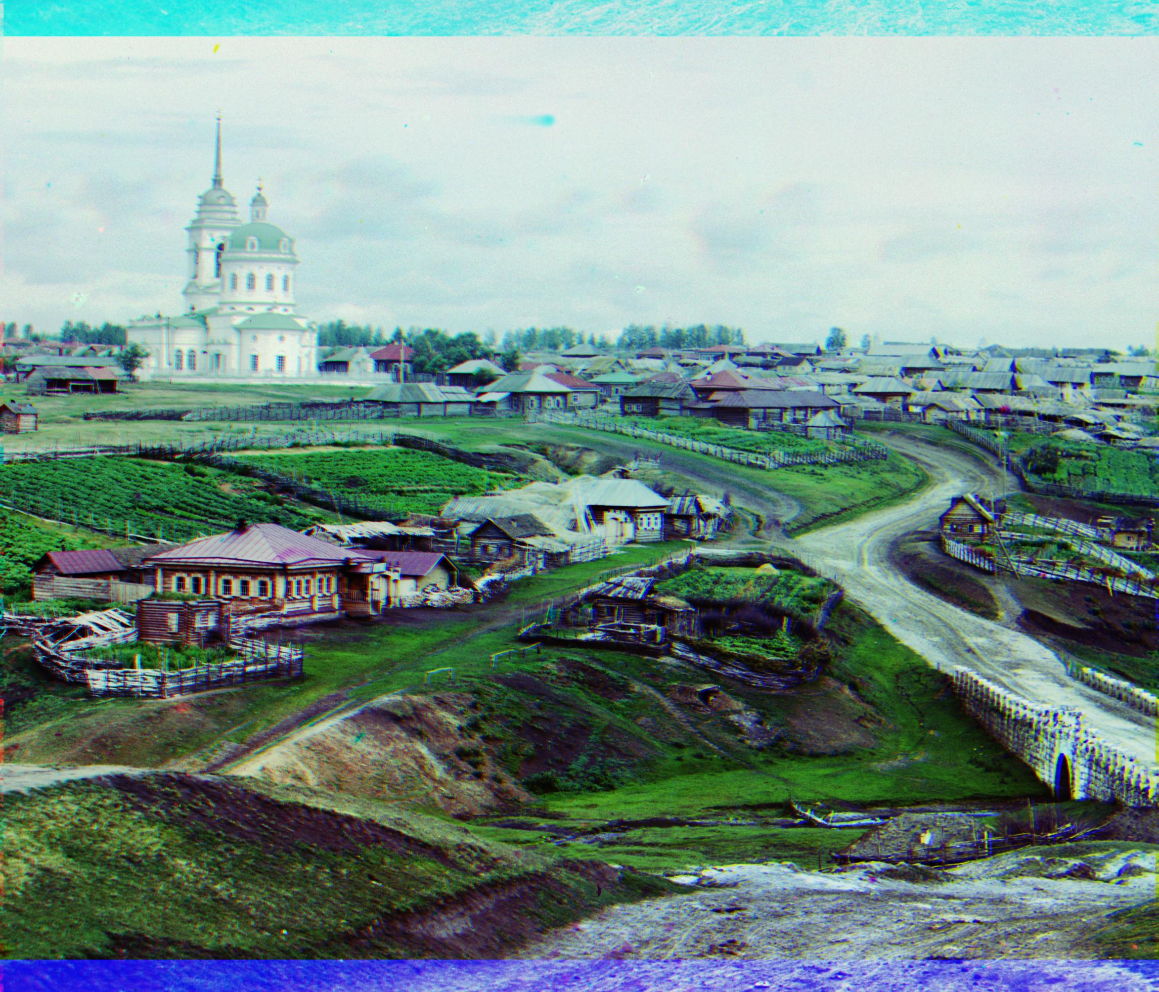
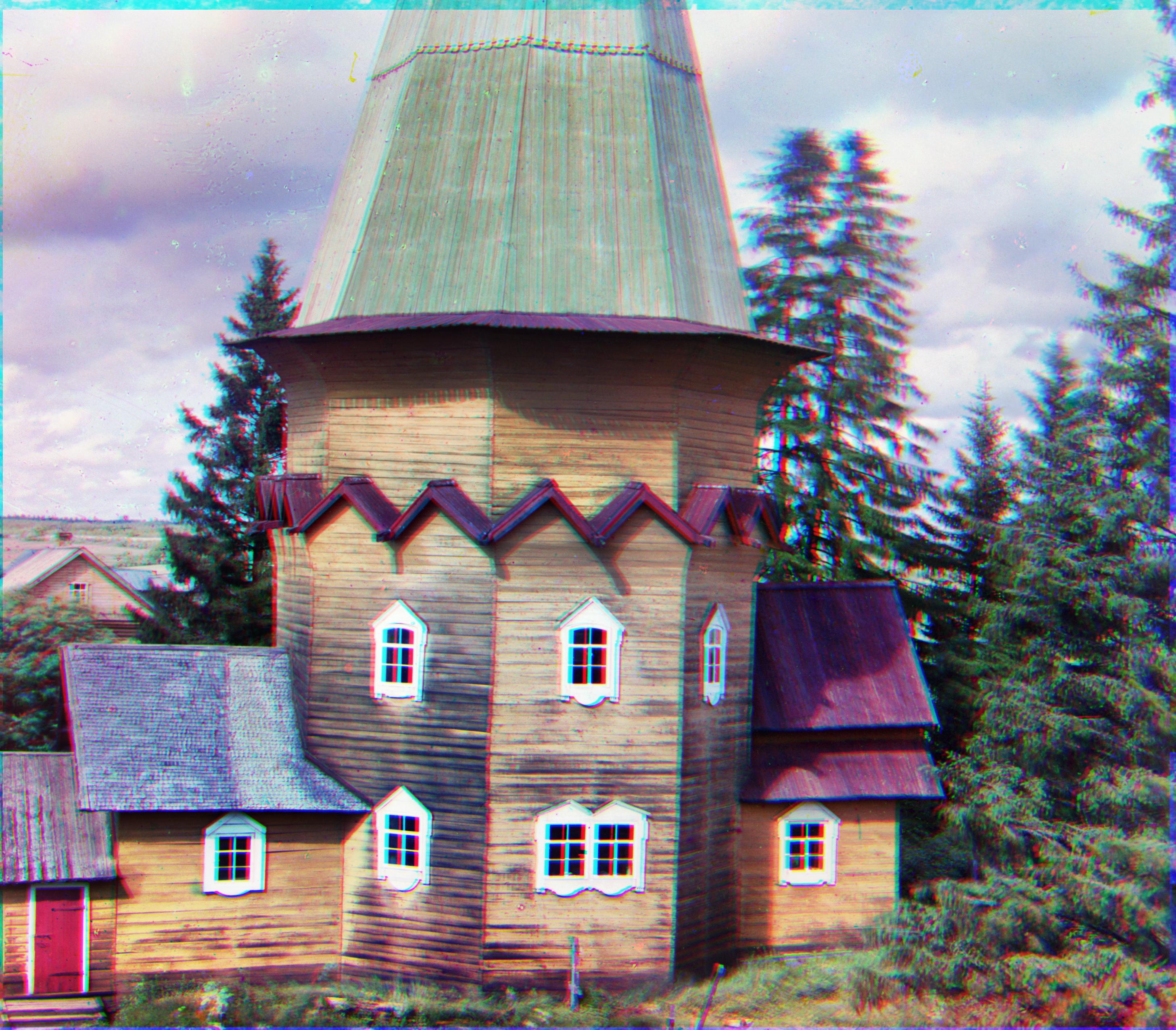
Village
Blue: (-12, 65), Red: (10, -73)
house
Blue: (-19, 10), Red: (19, -26)