In this project, we attempt to colorize glass negatives from the Prokudin-Gorskii collection. A man ahead of his time, Prokudin-Gorskii accurately predicted the use of red, green and blue color channels to represent color photos. Using these historic negatives, we attempt to recreate scenes from Russia in the early 1900s. The challenge is correctly aligning these negatives, and orienting them in the correct color channels to create a lifelike image.
Naive Image Alignment
Our first approach is to exhaustively test a set of displacement vectors in the range of [-15,15] pixels to try and find an (x,y) displacement vector that correctly aligns each set of color channels. To check the validity of each displacement, we use a measure of the sum of squared differences (SSD) between the two channels we are comparing. I parallelized the process of calculating the SSD for each set of displacement vectors, and chose the lowest SSD displacement between the green and blue channel and the red and blue channel (the blue channel is treated as fixed in this case). For small images, this worked fairly well, as you can see below.
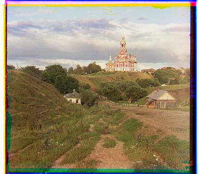 Cathedral.jpg, with our naive approach
Offsets: Green (5,2), Red (12,3)
Cathedral.jpg, with our naive approach
Offsets: Green (5,2), Red (12,3)
|
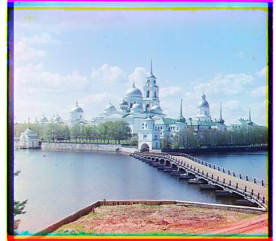 Monastery.jpg, with our naive approach
Offsets: Green (-3,2), Red (3,2)
Monastery.jpg, with our naive approach
Offsets: Green (-3,2), Red (3,2)
|
However, this approach falls flat for larger tif files, who span sizes of roughly 3000x3000. For these larger images, the potential displacement is much greater than the previous range of [-15,15] pixels, and calculating the SSD for each of these displacements is incredibly costly to perform on 3000x3000 images. To solve this, we look to an image pyramid approach.
Adding an Image Pyramid
To implement an image pyramid, we downscale the image and use our previous naive implementation. Then, we slowly calculate the correct displacement on higher quality versions of our image until we know the correct displacement on the full image. This approach is also great because it can be implemented recursively - we try to calculate the correct displacement on smaller and smaller versions of our image until we reach an image of roughly size 350x350, and then tweak our displacement as we run back up the stack and exhaustively test displacements in the range of [-3,3] pixels from the 'best guess' that we calculate from the most recently downsampled version of the image. Basically, we're able to obtain a best guess from a downscaled version of our image, and tweak the correct displacement on higher and higher quality versions of our image until we know the correct displacement for our full image.
This implementation works great for the small images that worked with our naive implementation as before, and works great on a subset of our larger images. A couple of the larger images are fairly "off", and I attribute this to a combination of the larger size (more variance in SSD), larger displacements (sometimes, the SSD search on the downscaled versions is off), and overall more detail in the picture (whcih could also throw off the SSD of the downscaled version). Take a look below:
 Lady.tif, with pyramid implementation
Offsets: Green (56,8), Red (102,15)
Lady.tif, with pyramid implementation
Offsets: Green (56,8), Red (102,15)
|
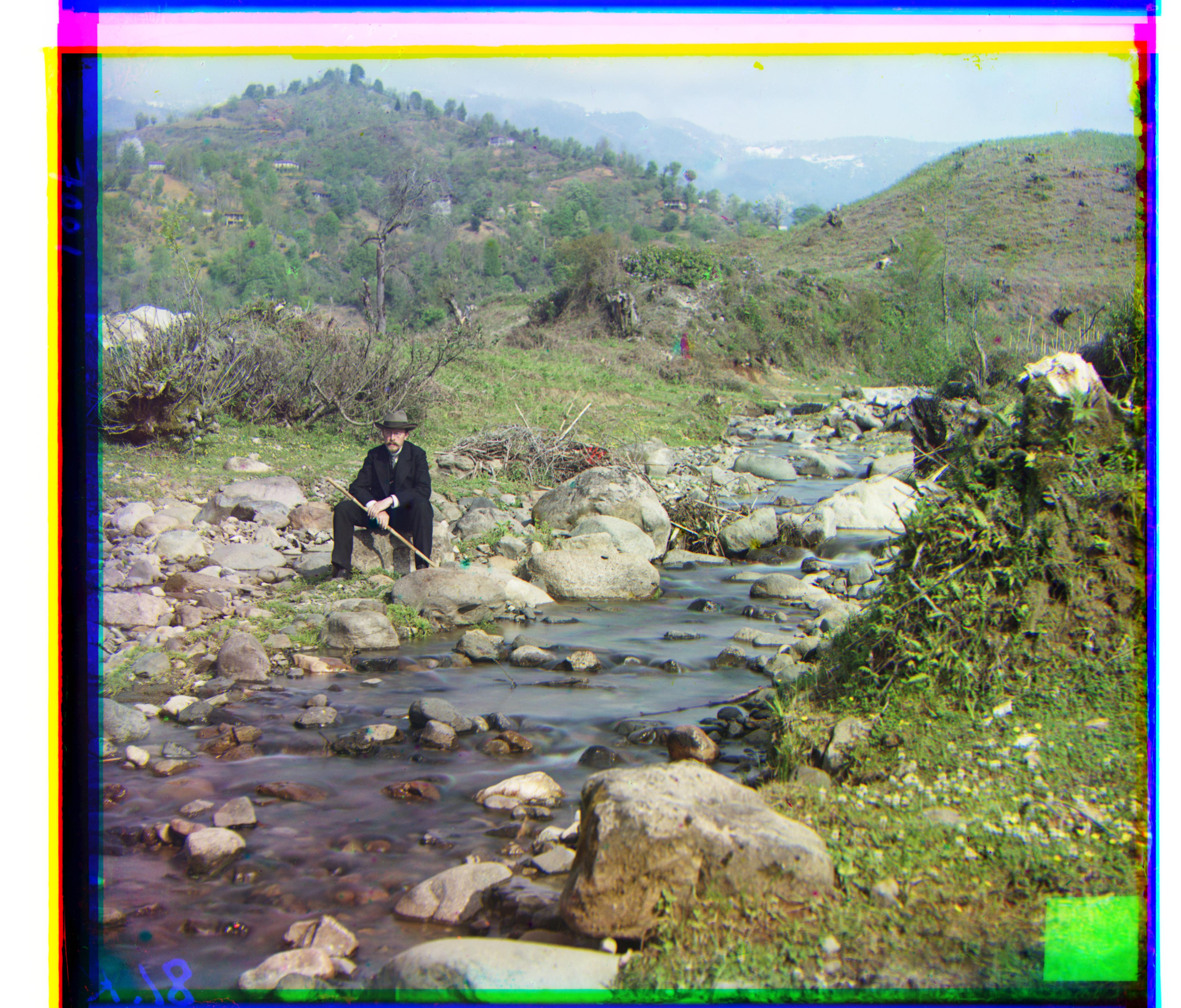 Self_portrait.tif, with pyramid implementation
Offsets: Green (76,28), Red (172,37)
Self_portrait.tif, with pyramid implementation
Offsets: Green (76,28), Red (172,37)
|
However, this approach runs into issues on a few of the images:
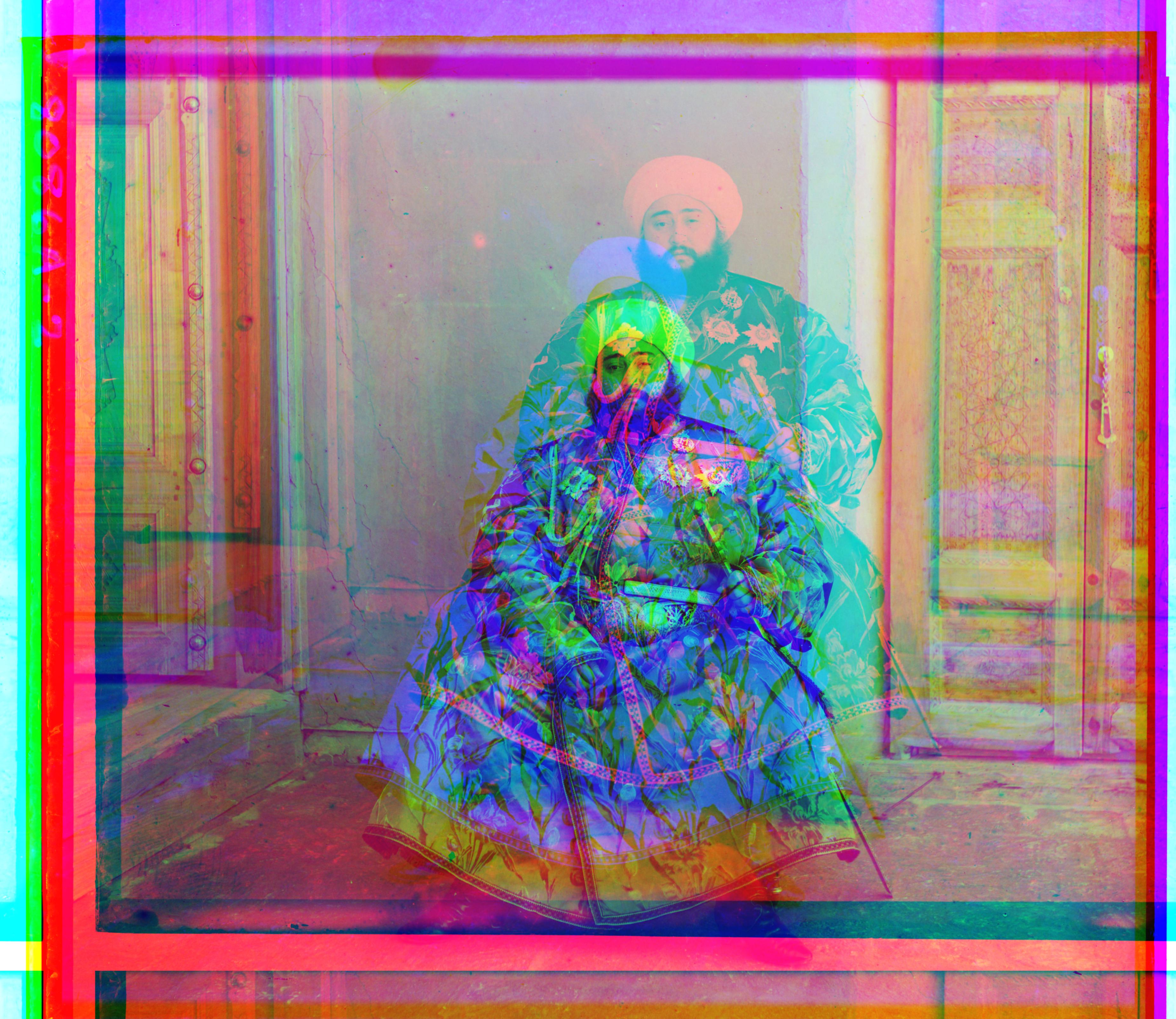 emir.tif, with pyramid implementation
Offsets: Green (241,47), Red (-152,215)
emir.tif, with pyramid implementation
Offsets: Green (241,47), Red (-152,215)
|
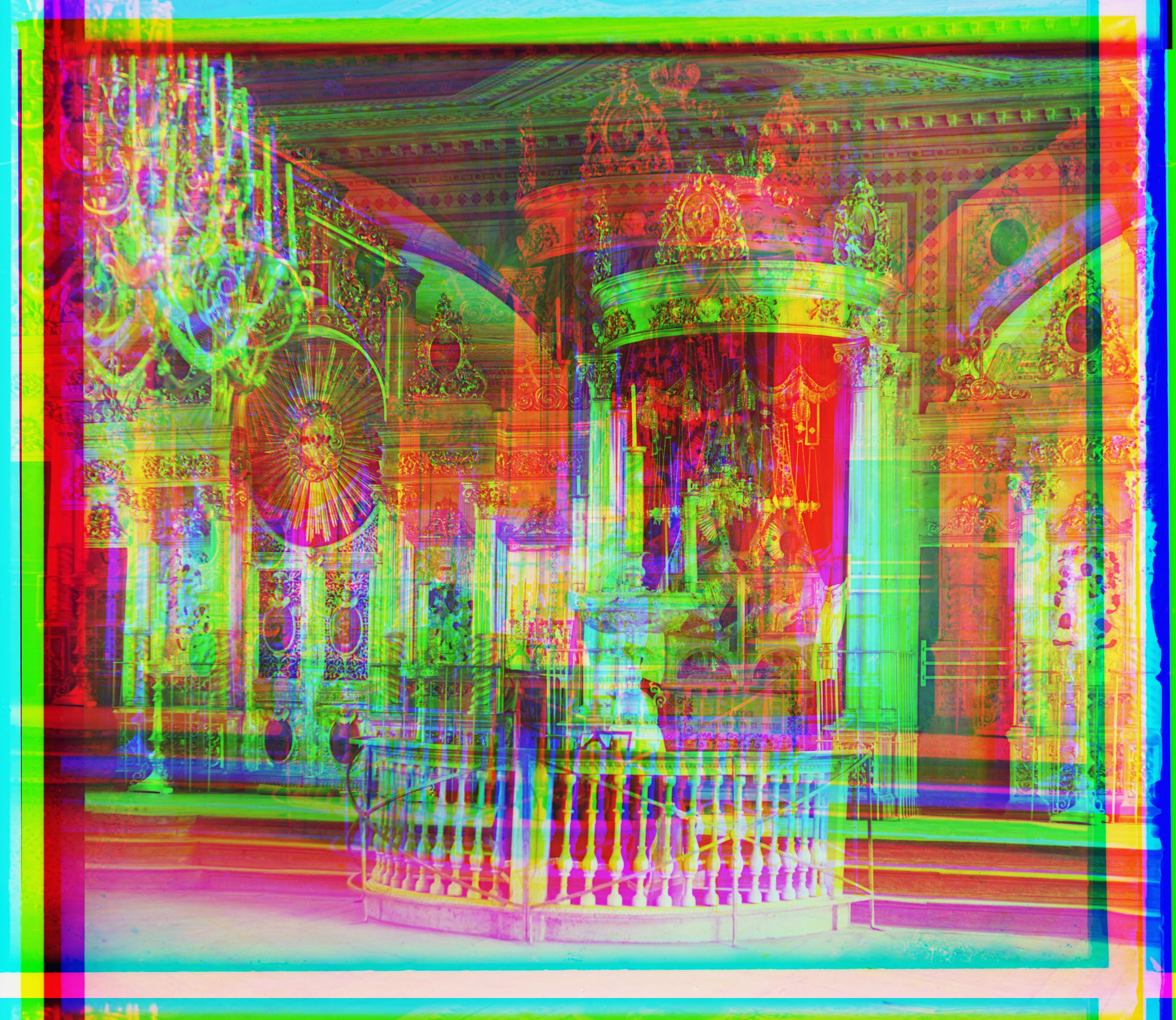 Icon.tif, with pyramid implementation
Offsets: Green (157,69), Red (-70,-166)
Icon.tif, with pyramid implementation
Offsets: Green (157,69), Red (-70,-166)
|
Bells and Whistles
To combat the inaccuraces in the image pyramid approach, I decided that better features were needed than the raw pixels. I ran a sobel filter over the images before running the image pyramid and SSD scheme that was used before, and this improved accuracy drastically. In addition, I was able to relax some of the conditions that I set previously in the interest of accuracy, and this also improved overall runtime.
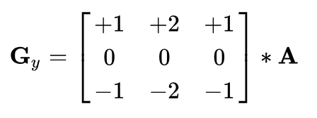
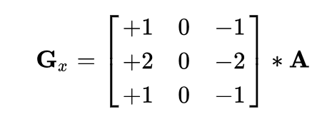
A sobel filter is a fairly naive edge detector that is produced from a composite of the result of a horizontal edge detector and a vertical edge detector. The horizontal and vertical edge detectors are shown below:
 Horizontal edge detector
|
 Vertical edge detector
|
The image is convolved with each detector, and the product of the sobel filter is found by taking the square root of the addition of the squares of the horizontal and vertical edge detector images. This provides much greater accuracy and efficiency, and the final images can be seen below (contrast the before and after emir.tif and icon.tif):
Final Images
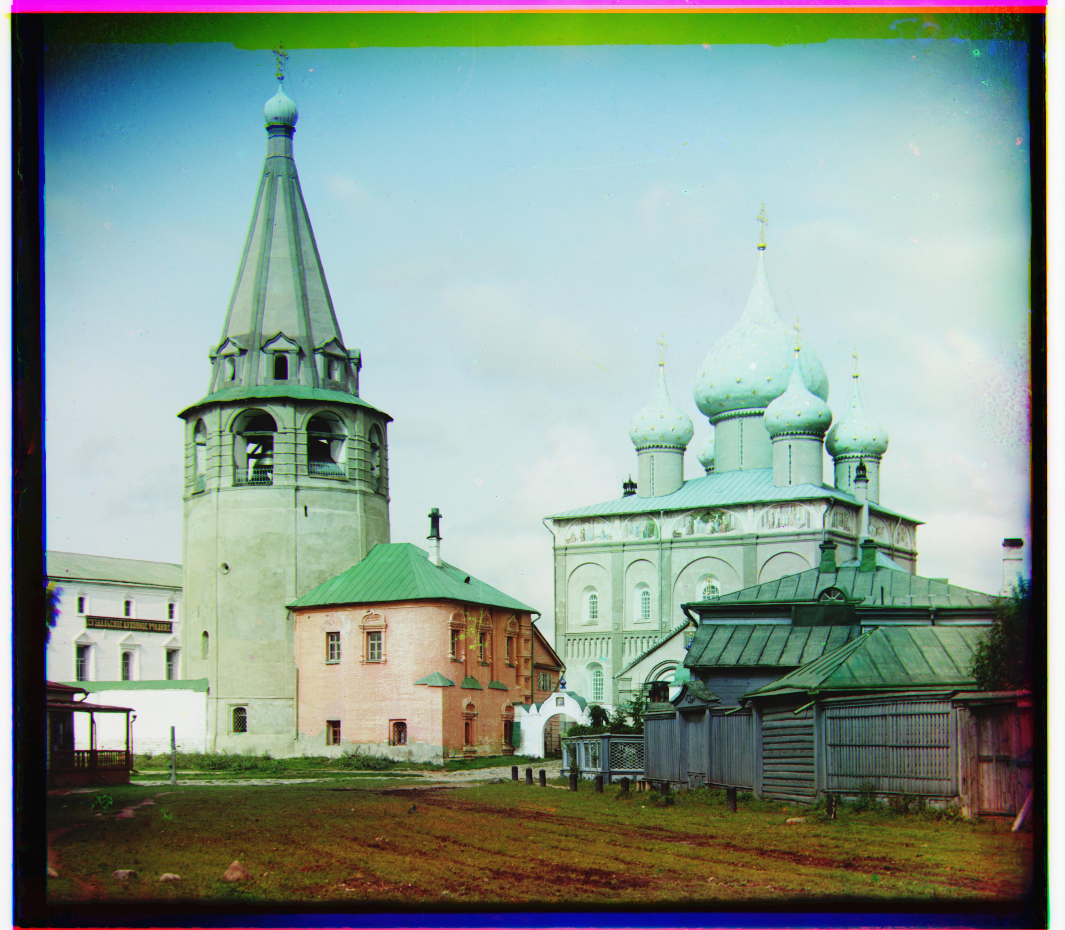
 cathedral.jpg
Offsets: Green (5,2), Red (12,3)
cathedral.jpg
Offsets: Green (5,2), Red (12,3)
|
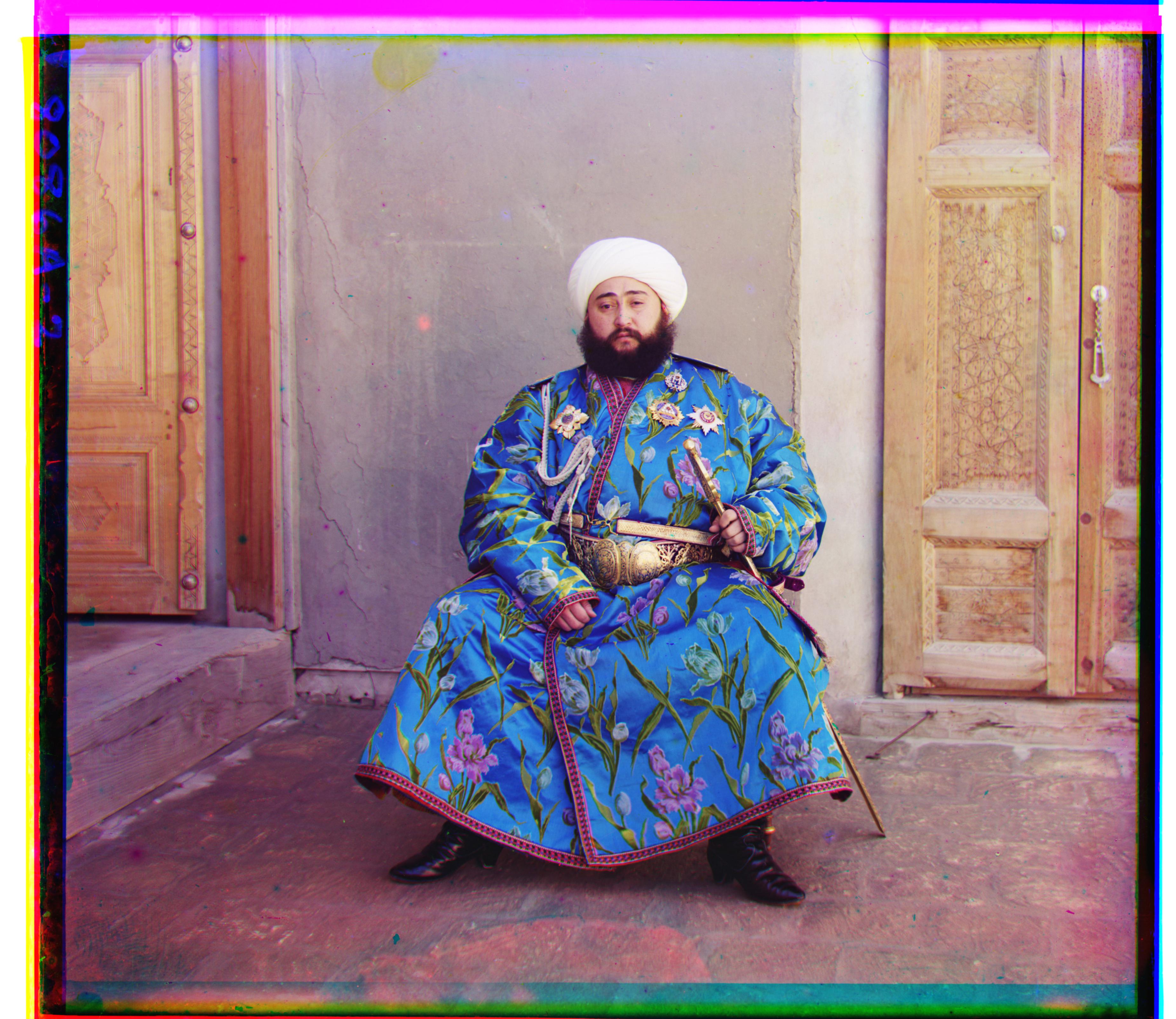 emir.tif
Offsets: Green (49,24), Red (107,40)
emir.tif
Offsets: Green (49,24), Red (107,40)
|
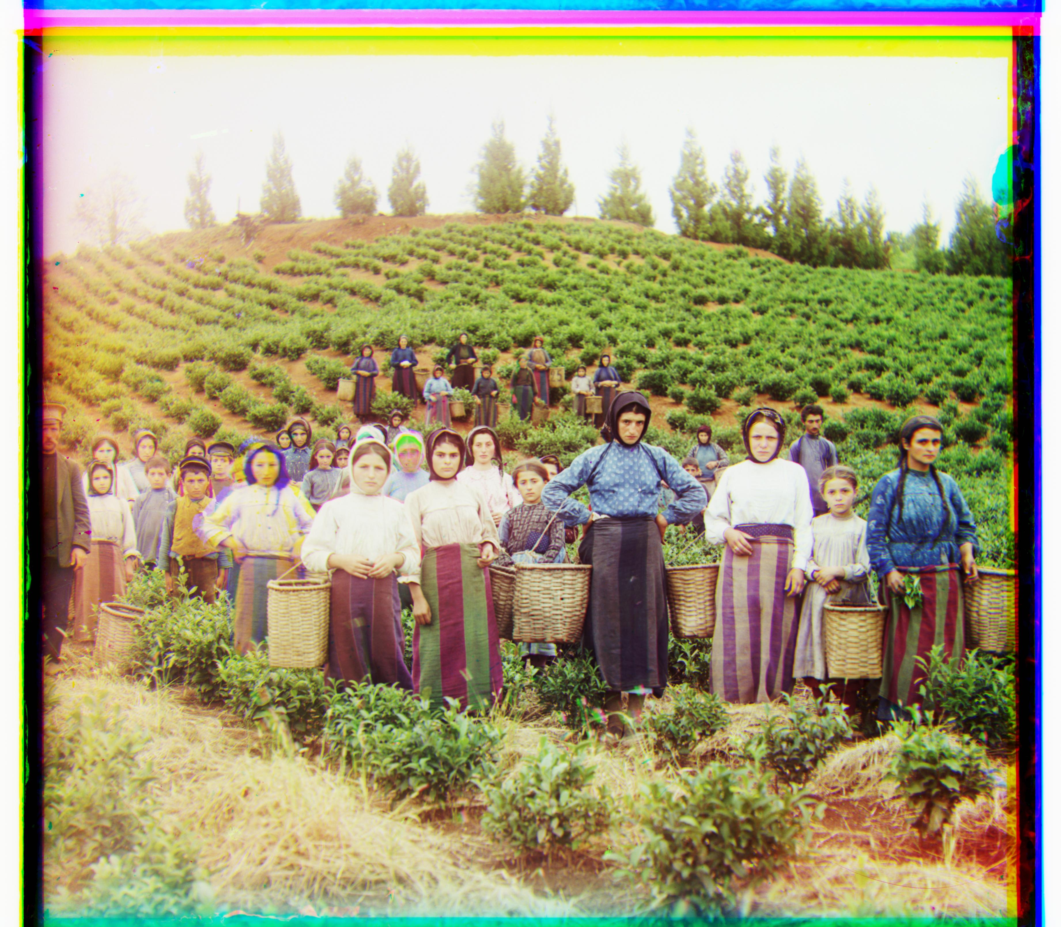 harvesters.tif
Offsets: Green (60,17), Red (124,14)
harvesters.tif
Offsets: Green (60,17), Red (124,14)
|
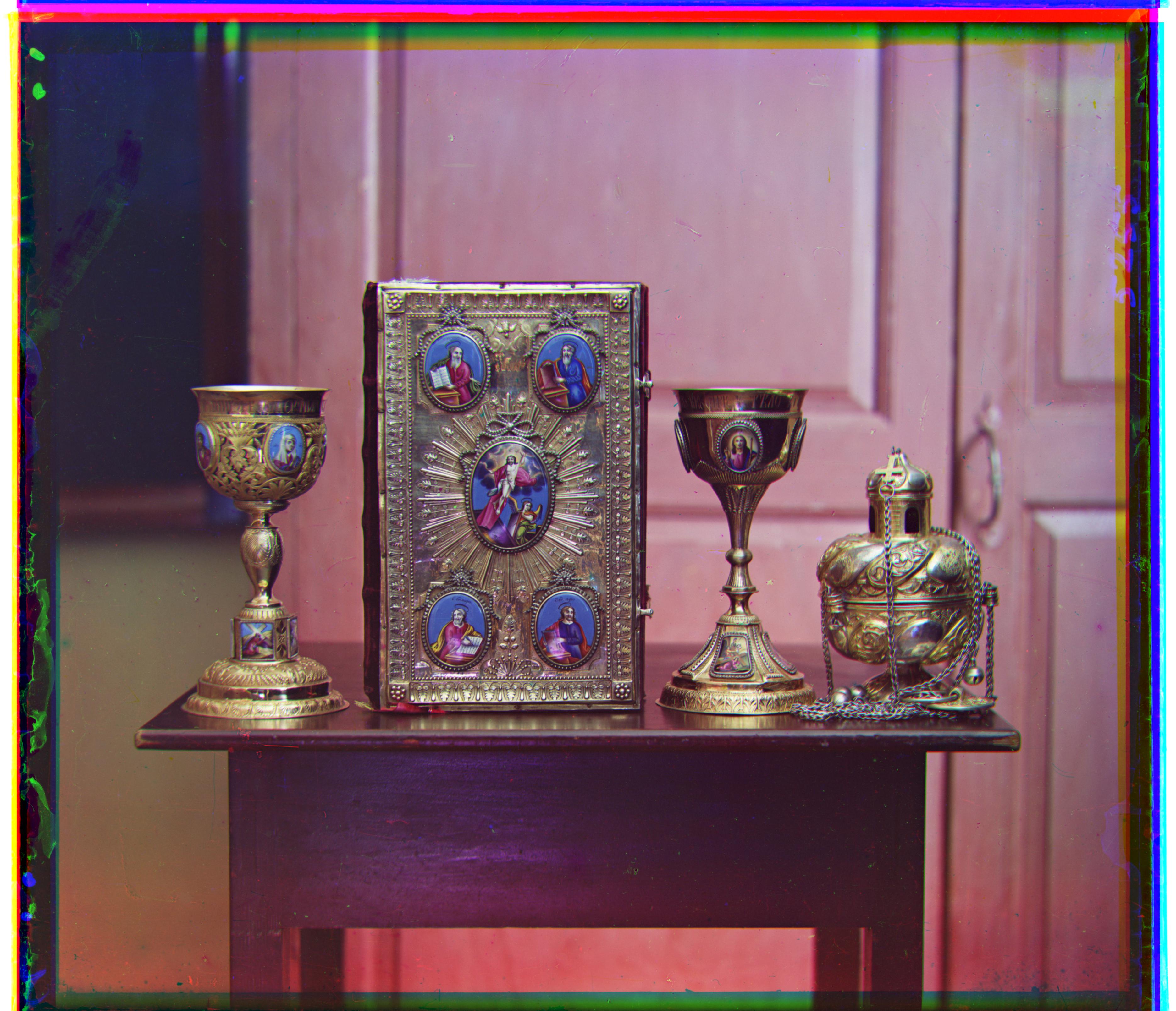
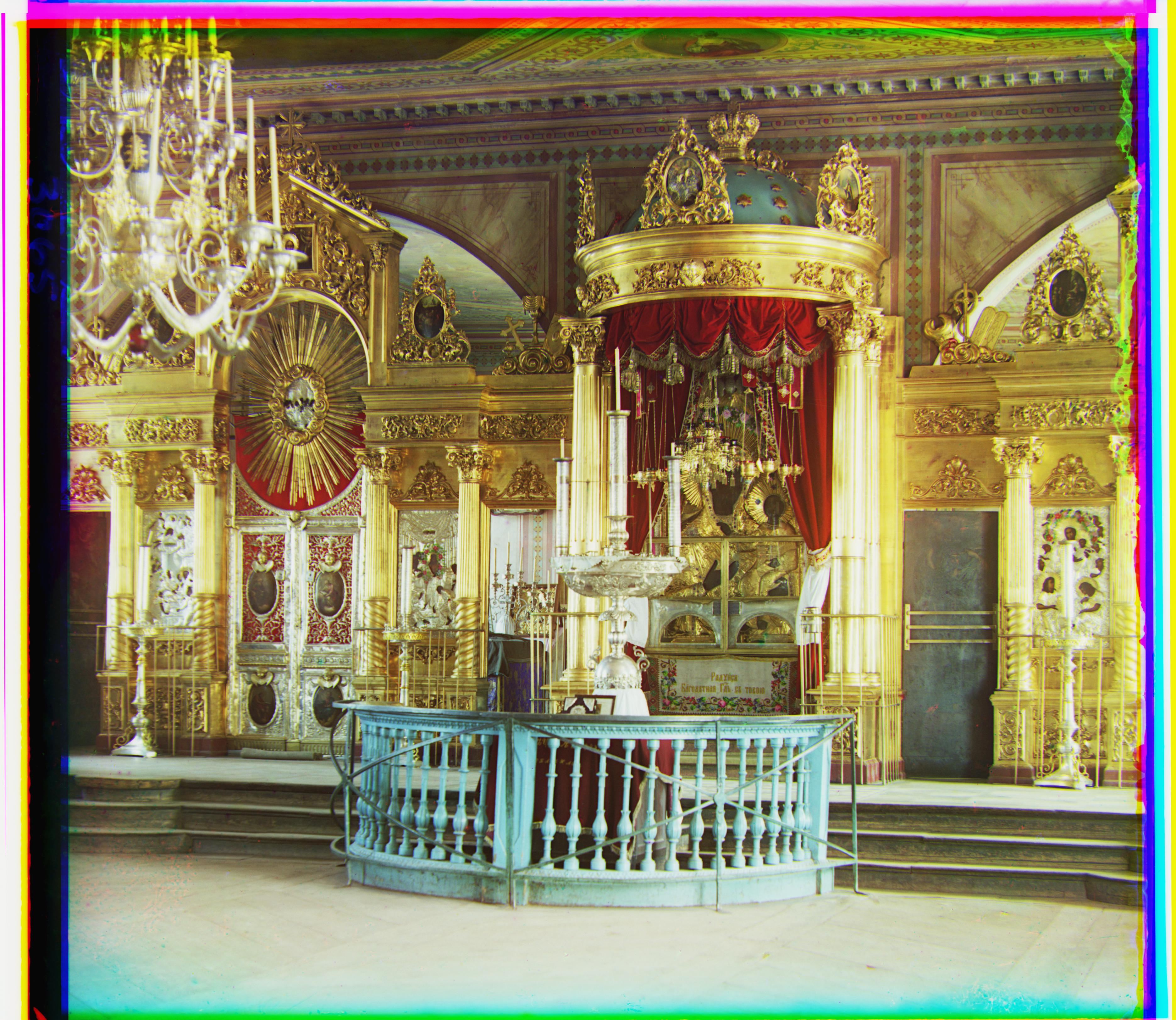 icon.tif
Offsets: Green (42,17), Red (90,23)
icon.tif
Offsets: Green (42,17), Red (90,23)
|
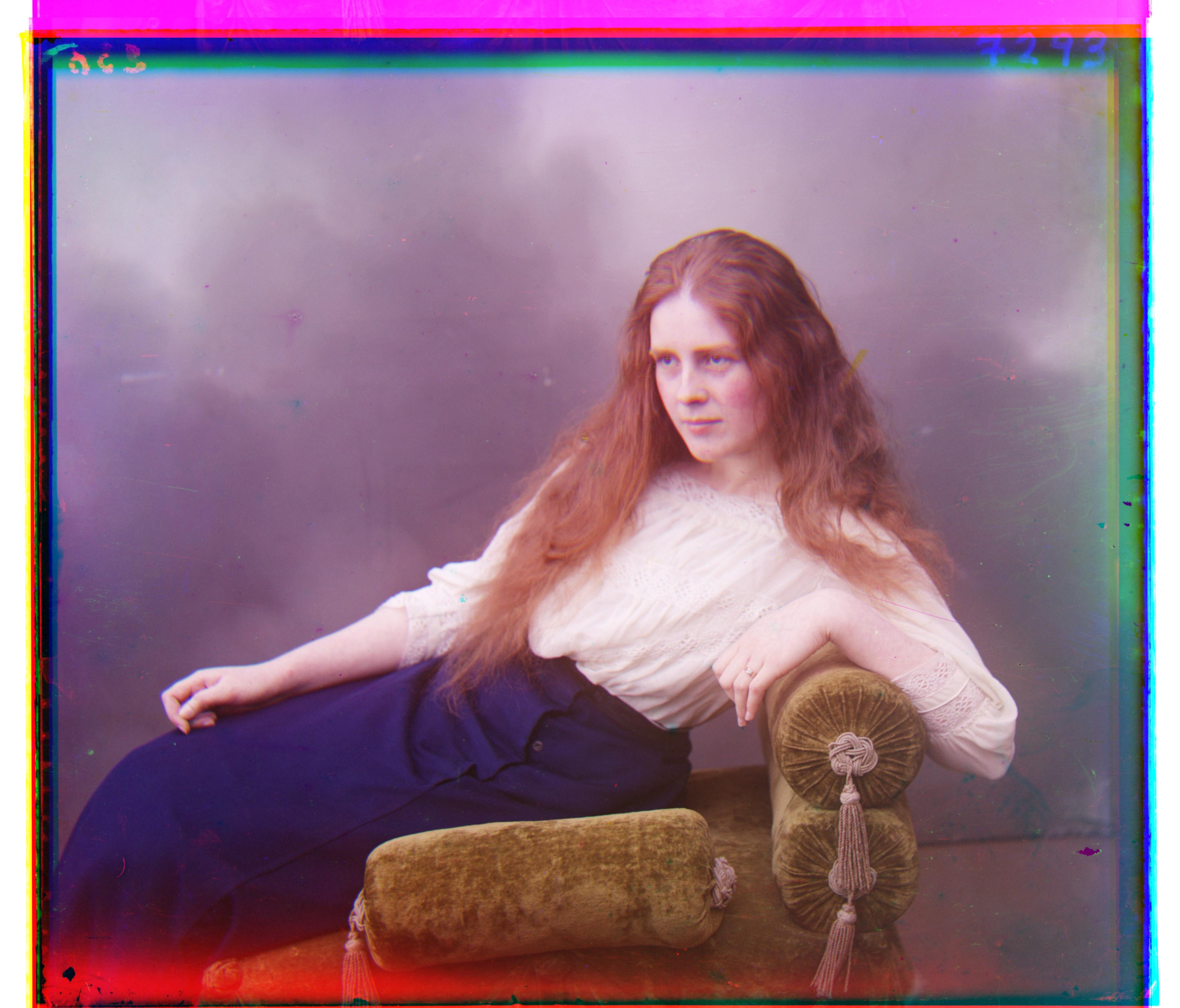 lady.tif
Offsets: Green (56,9), Red (120,13)
lady.tif
Offsets: Green (56,9), Red (120,13)
|
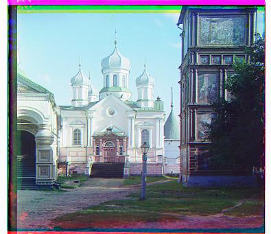
 monastery.jpg
Offsets: Green (-3,2), Red (3,2)
monastery.jpg
Offsets: Green (-3,2), Red (3,2)
|
 nativity.jpg
Offsets: Green (3,1), Red (7,1)
nativity.jpg
Offsets: Green (3,1), Red (7,1)
|
 self_portrait.tif
Offsets: Green (78,29), Red (176,37)
self_portrait.tif
Offsets: Green (78,29), Red (176,37)
|
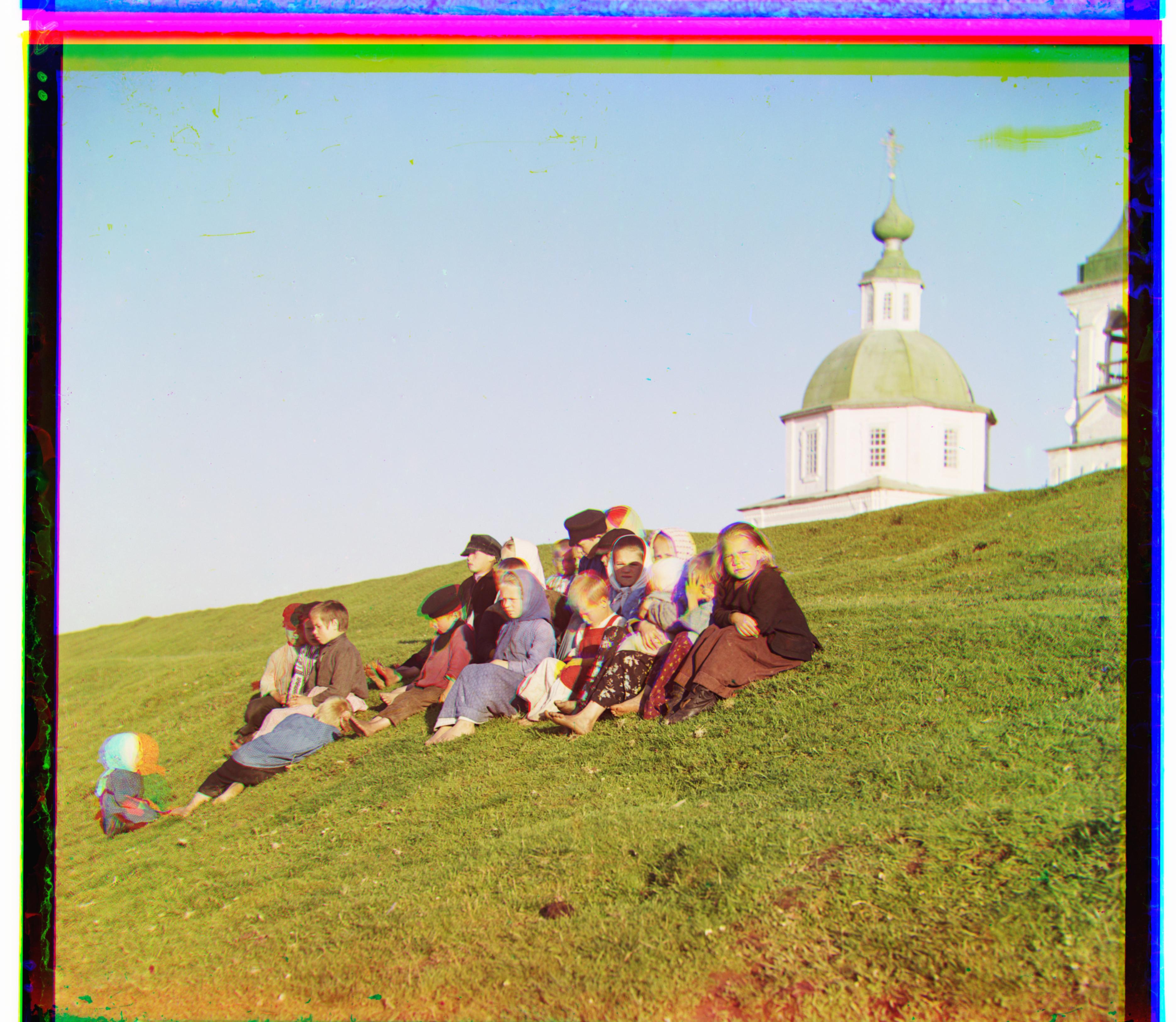
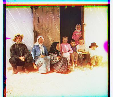 settlers.jpg
Offsets: Green (7,0), Red (14,-1)
settlers.jpg
Offsets: Green (7,0), Red (14,-1)
|
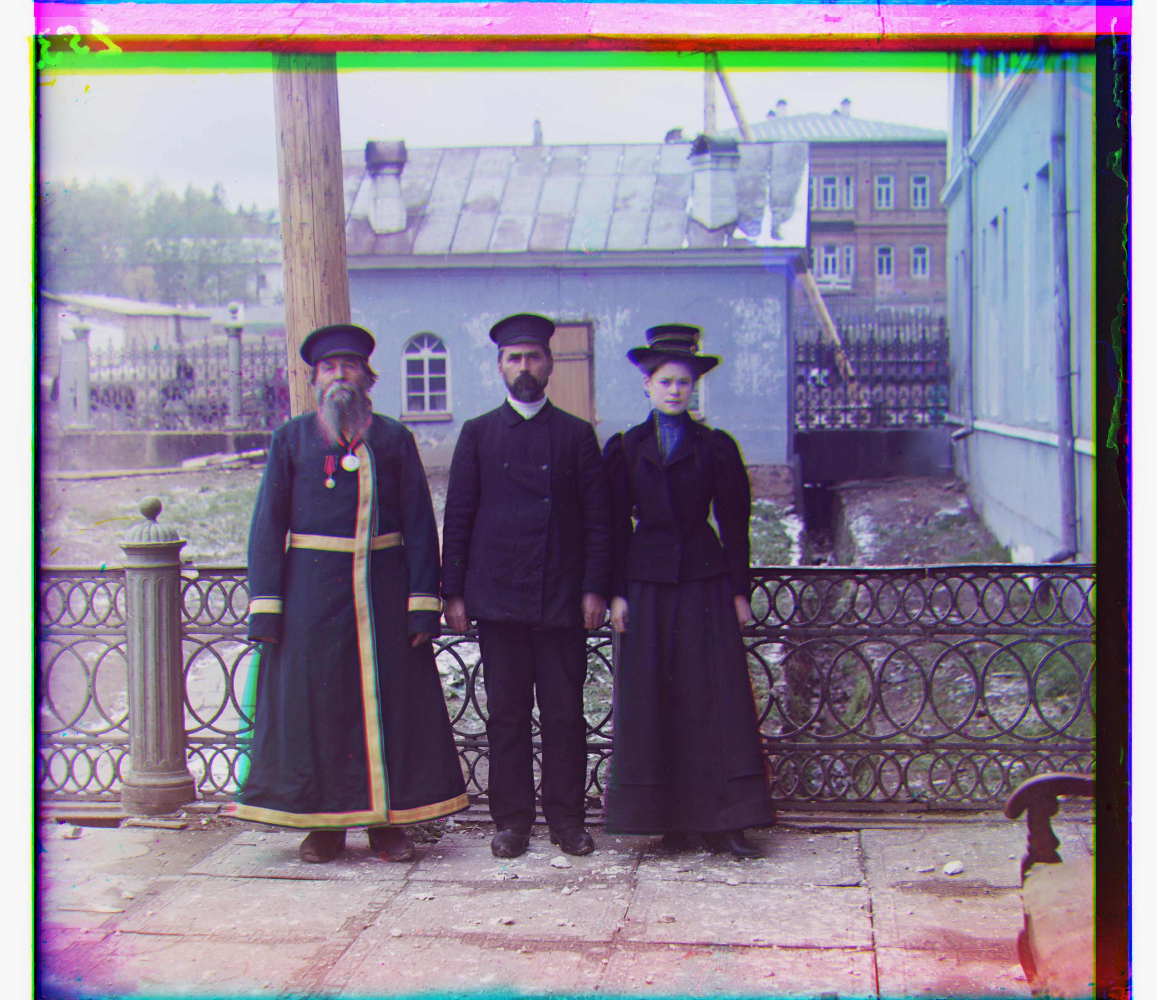 three_generations.tif
Offsets: Green (54,12), Red (111,9)
three_generations.tif
Offsets: Green (54,12), Red (111,9)
|
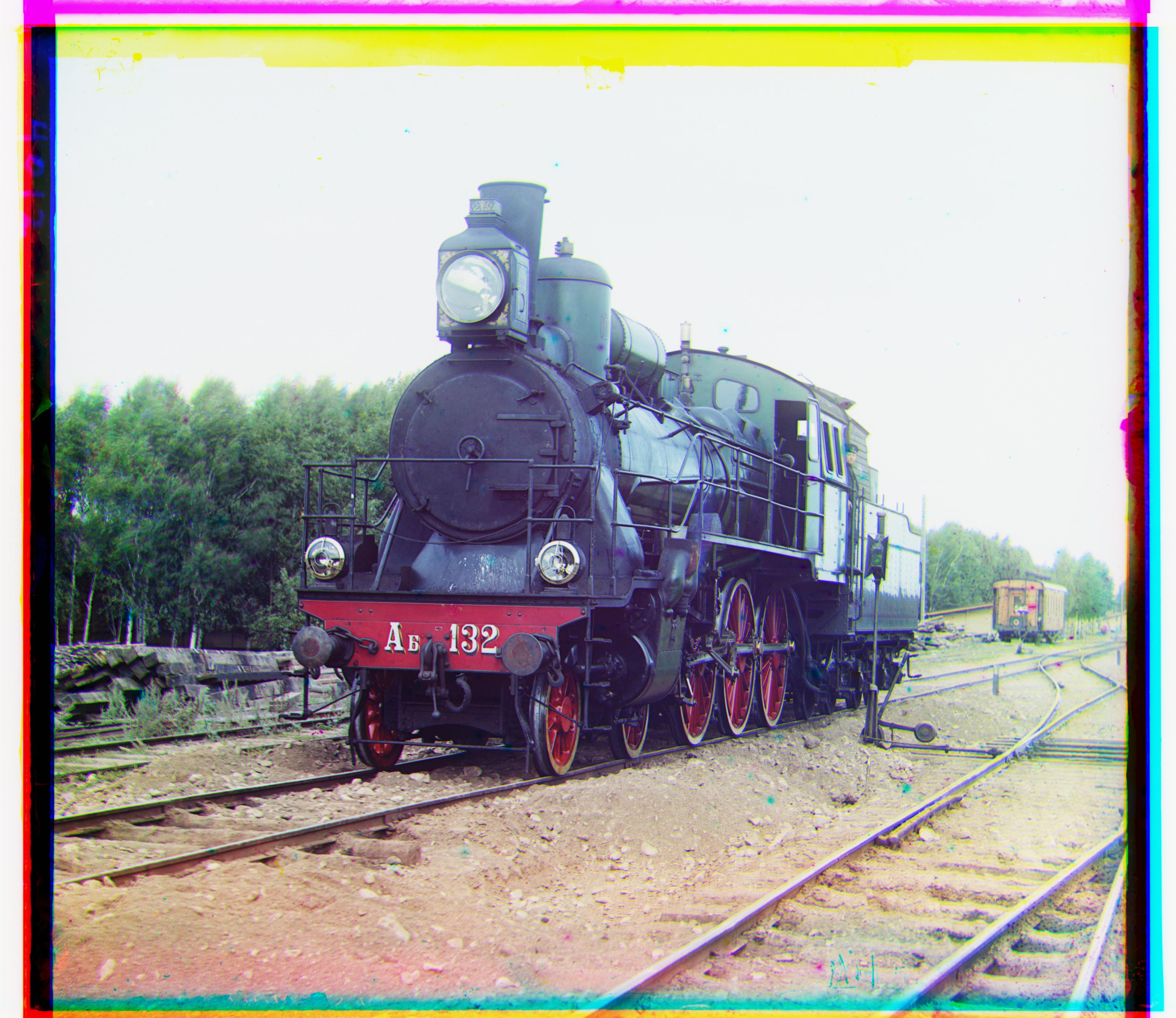 train.tif
Offsets: Green (42,3), Red (85,29)
train.tif
Offsets: Green (42,3), Red (85,29)
|
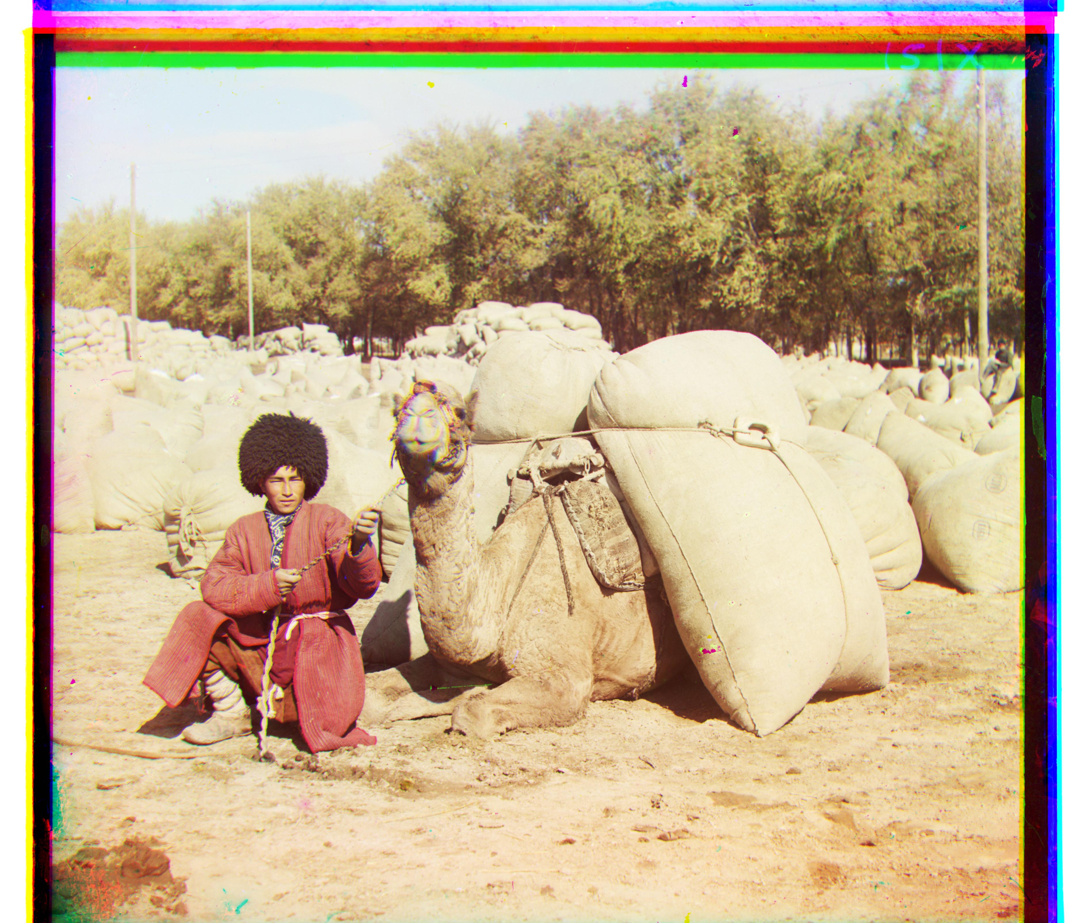 turkmen.tif
Offsets: Green (57,22), Red (117,28)
turkmen.tif
Offsets: Green (57,22), Red (117,28)
|
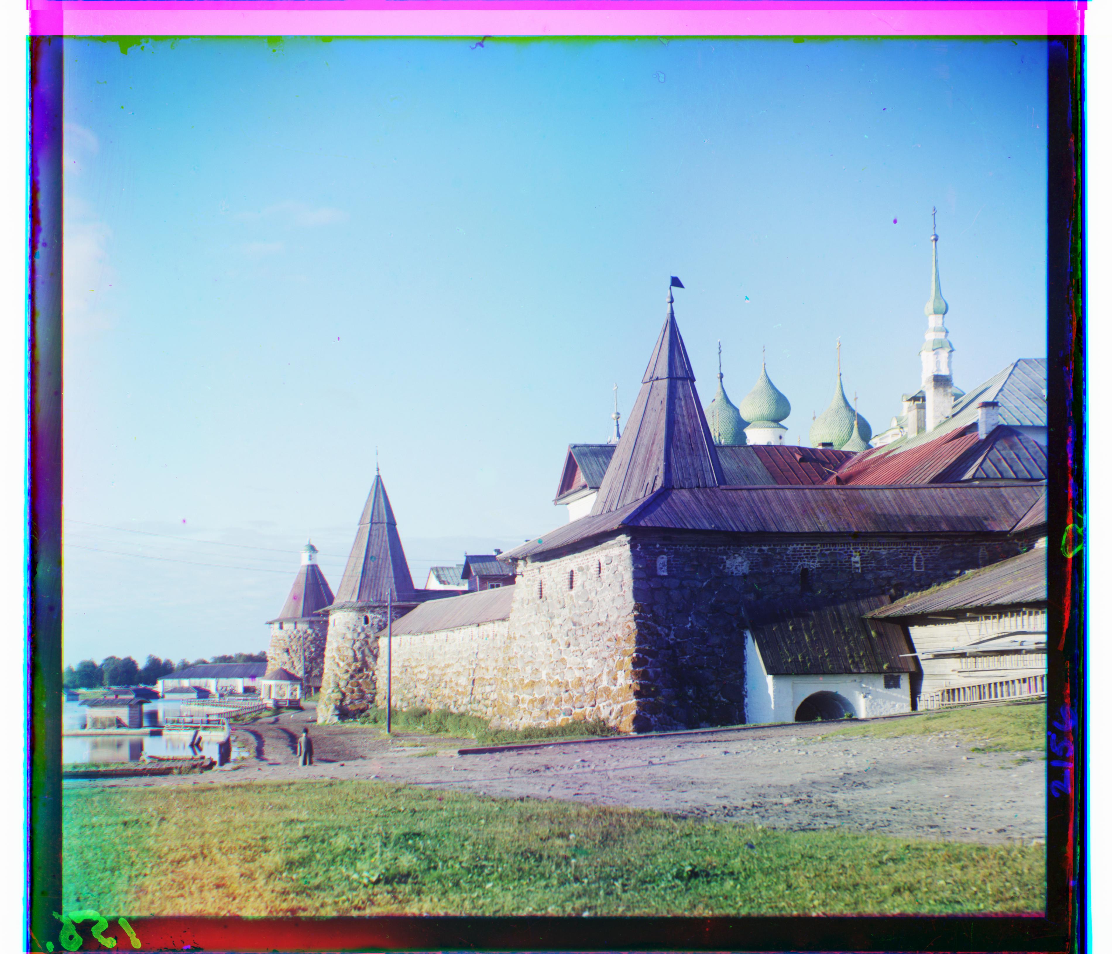
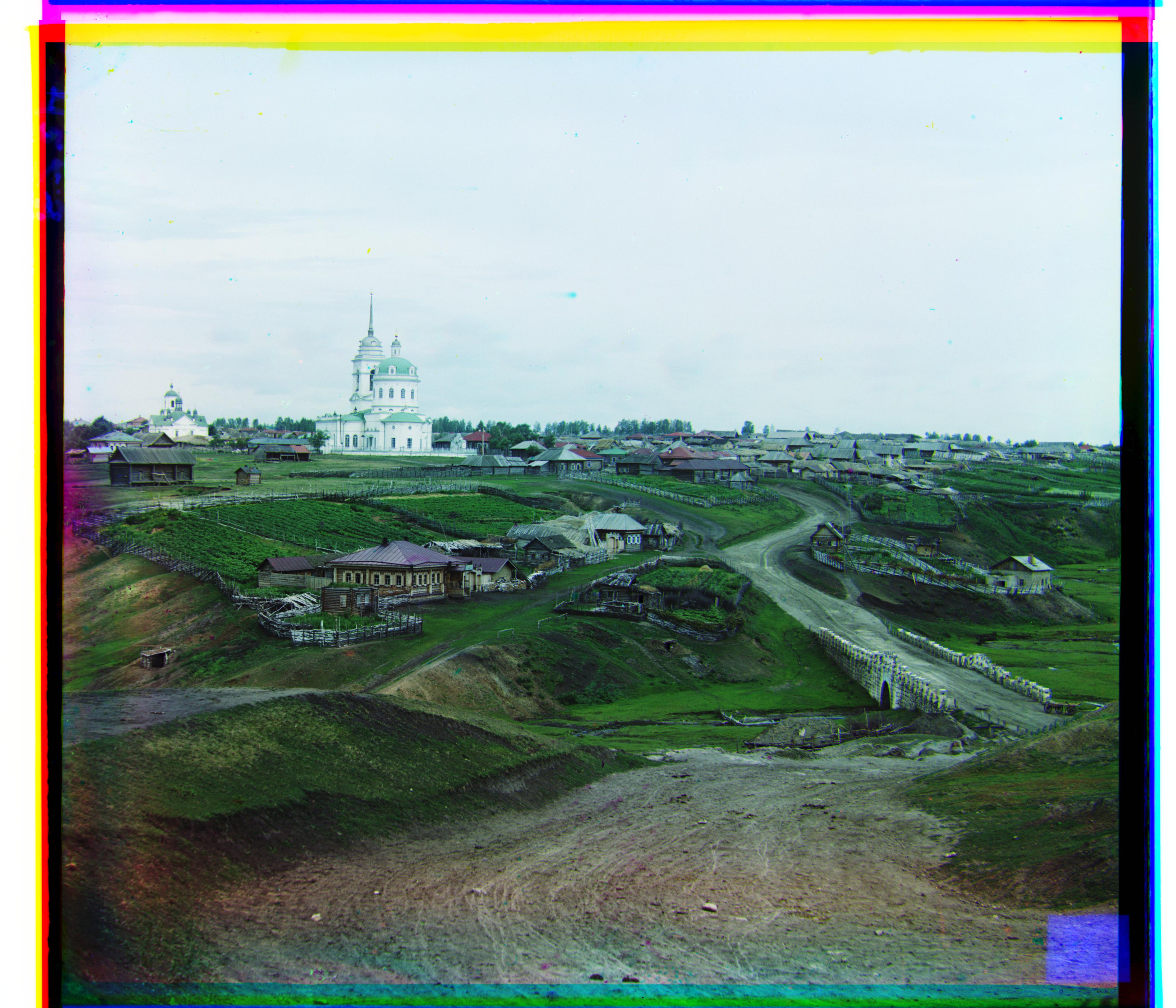 village.tif
Offsets: Green (64,10), Red (137,21)
village.tif
Offsets: Green (64,10), Red (137,21)
|
Extras from the Prokudin-Gorskii