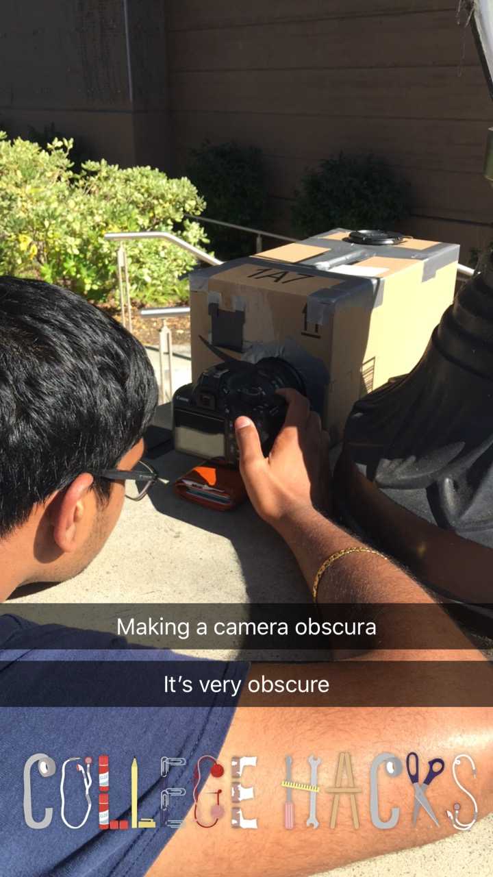
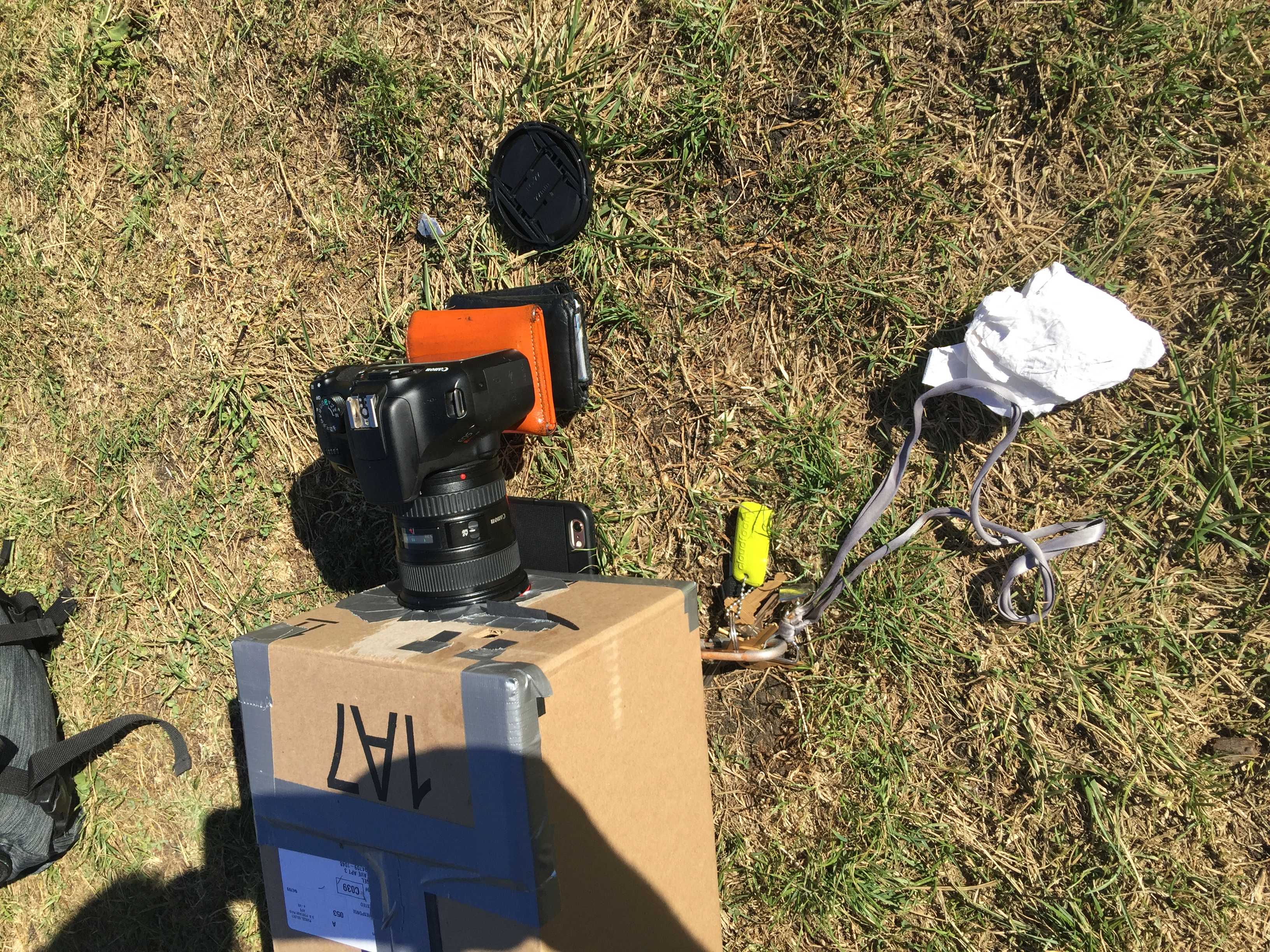
iPhone
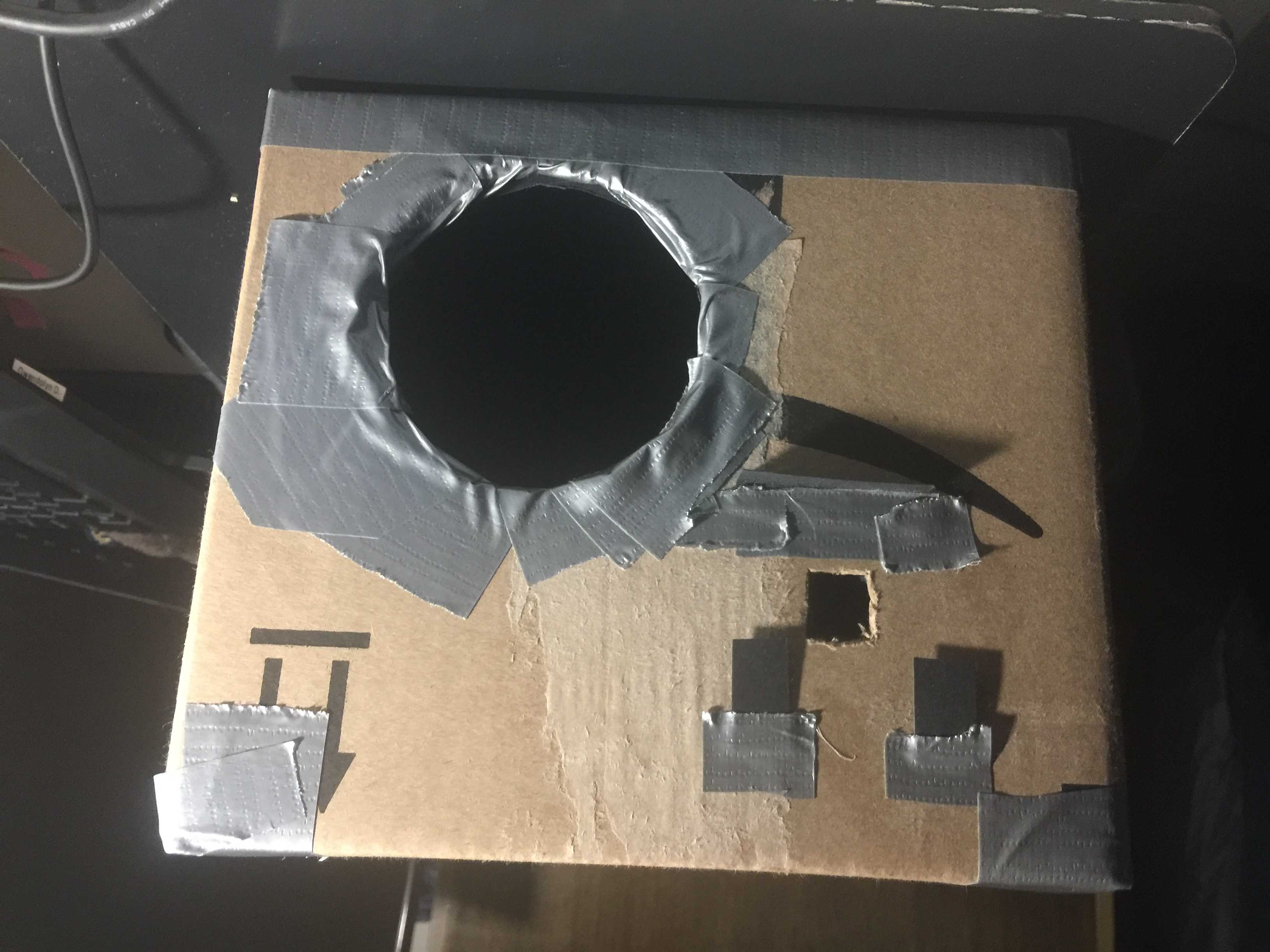
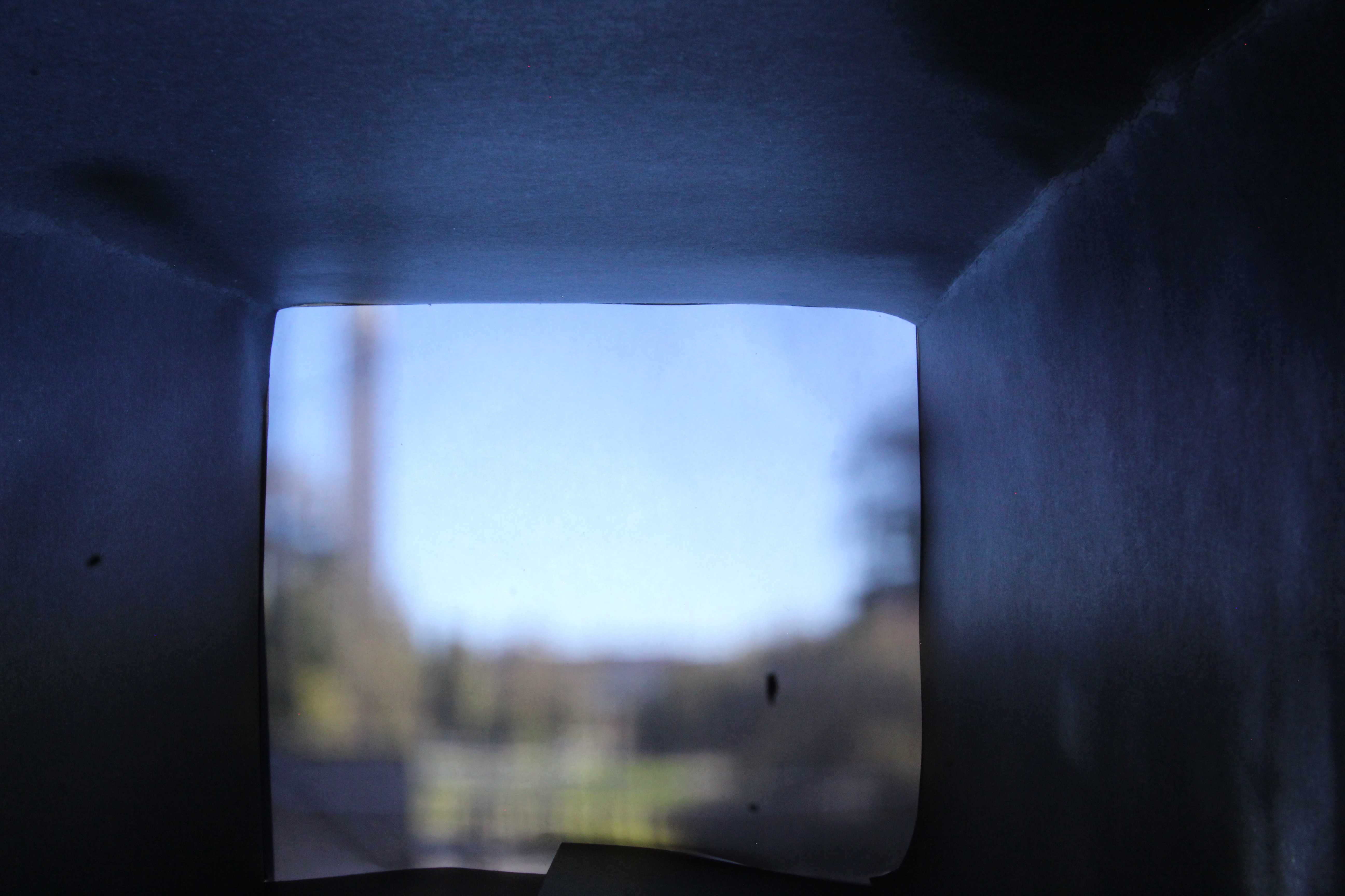
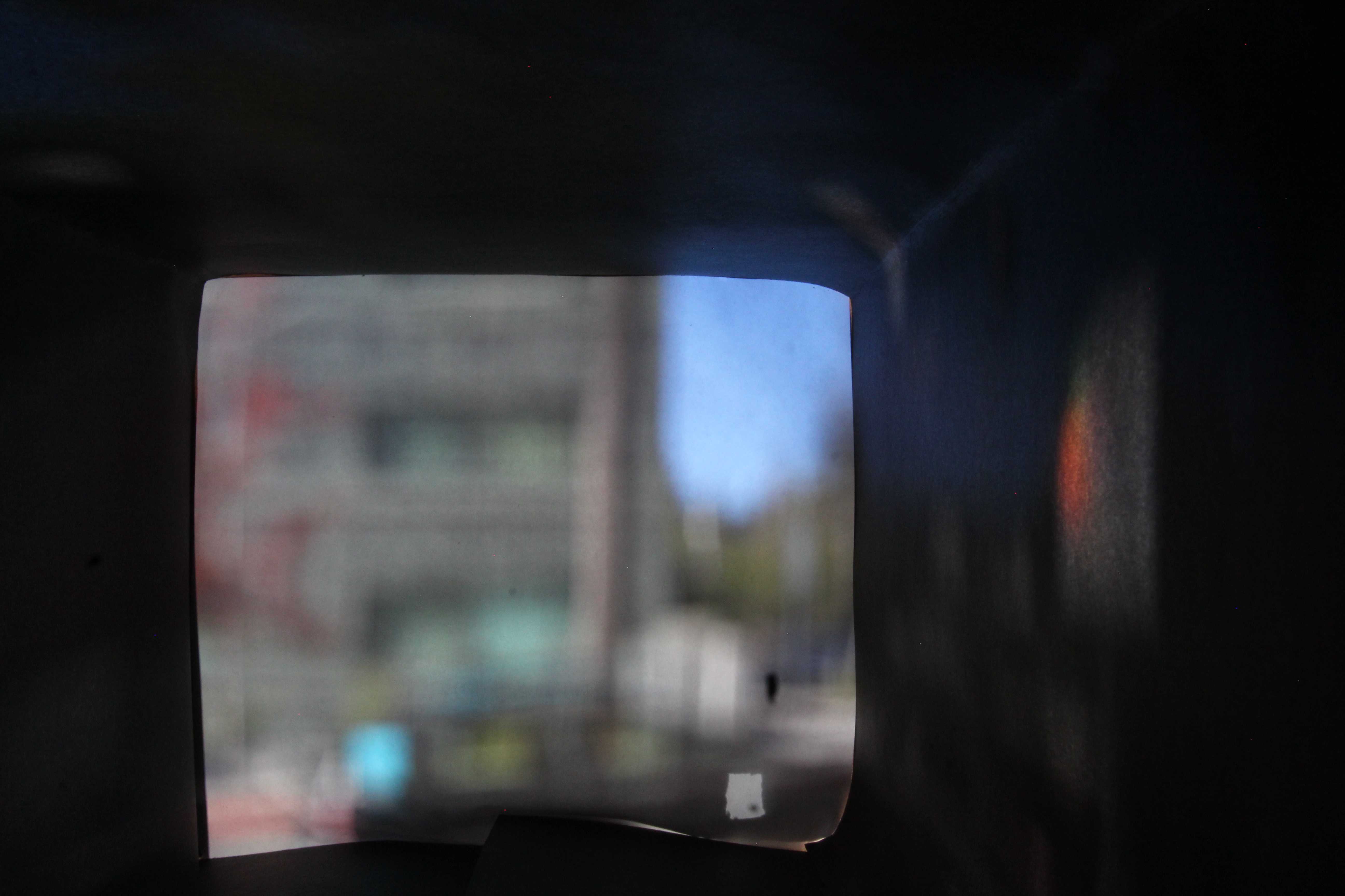
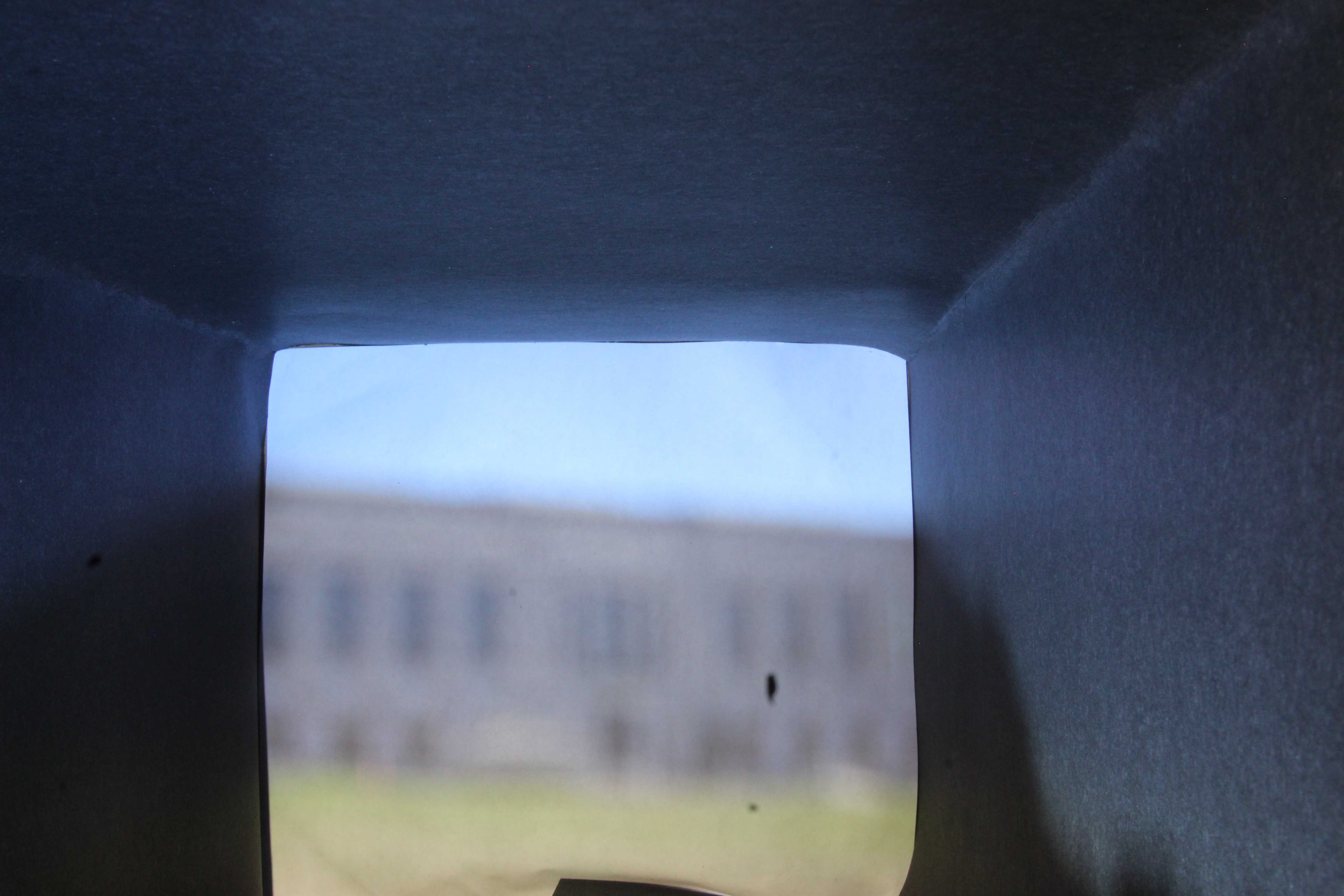
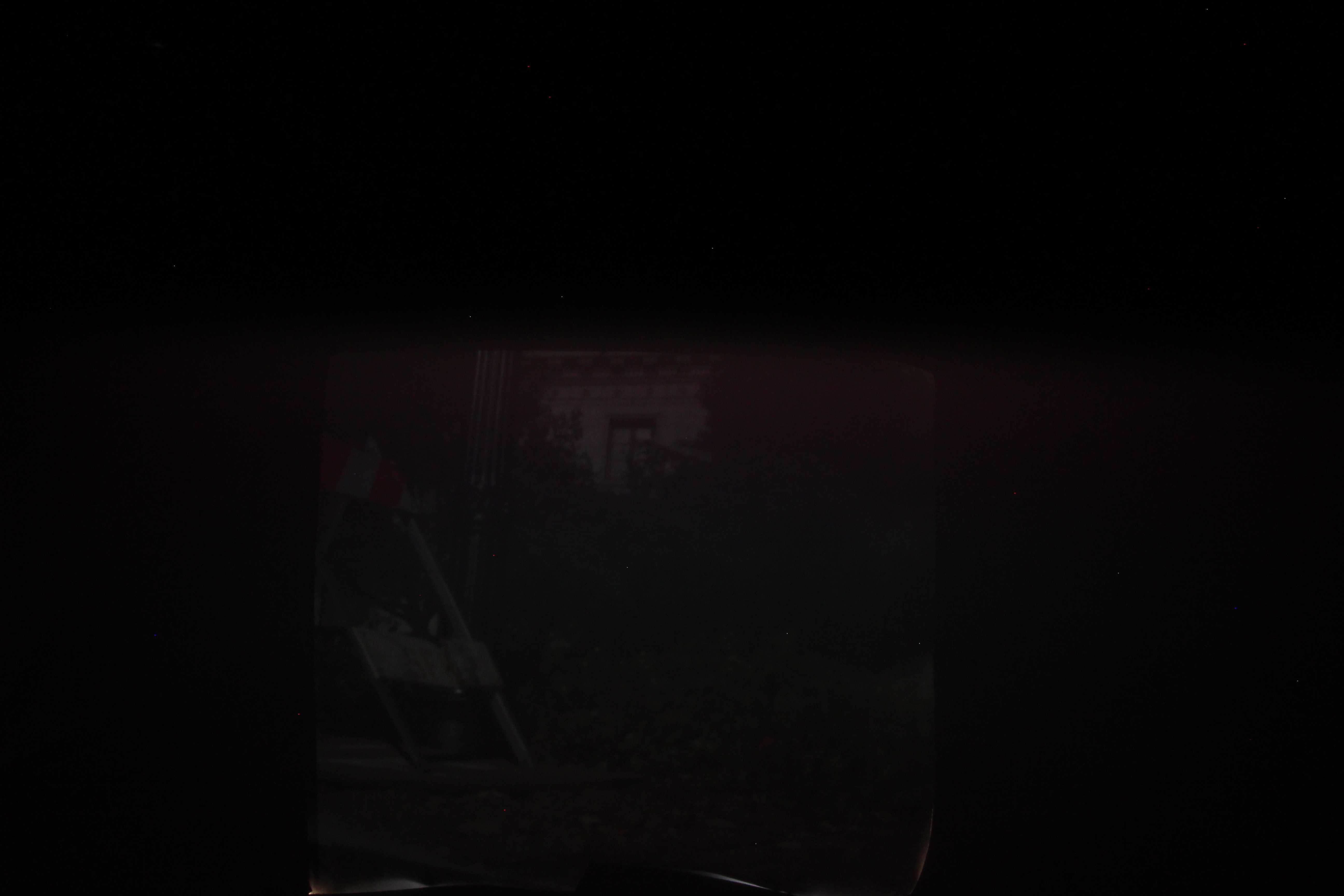
Width: Open ~3x3cm square
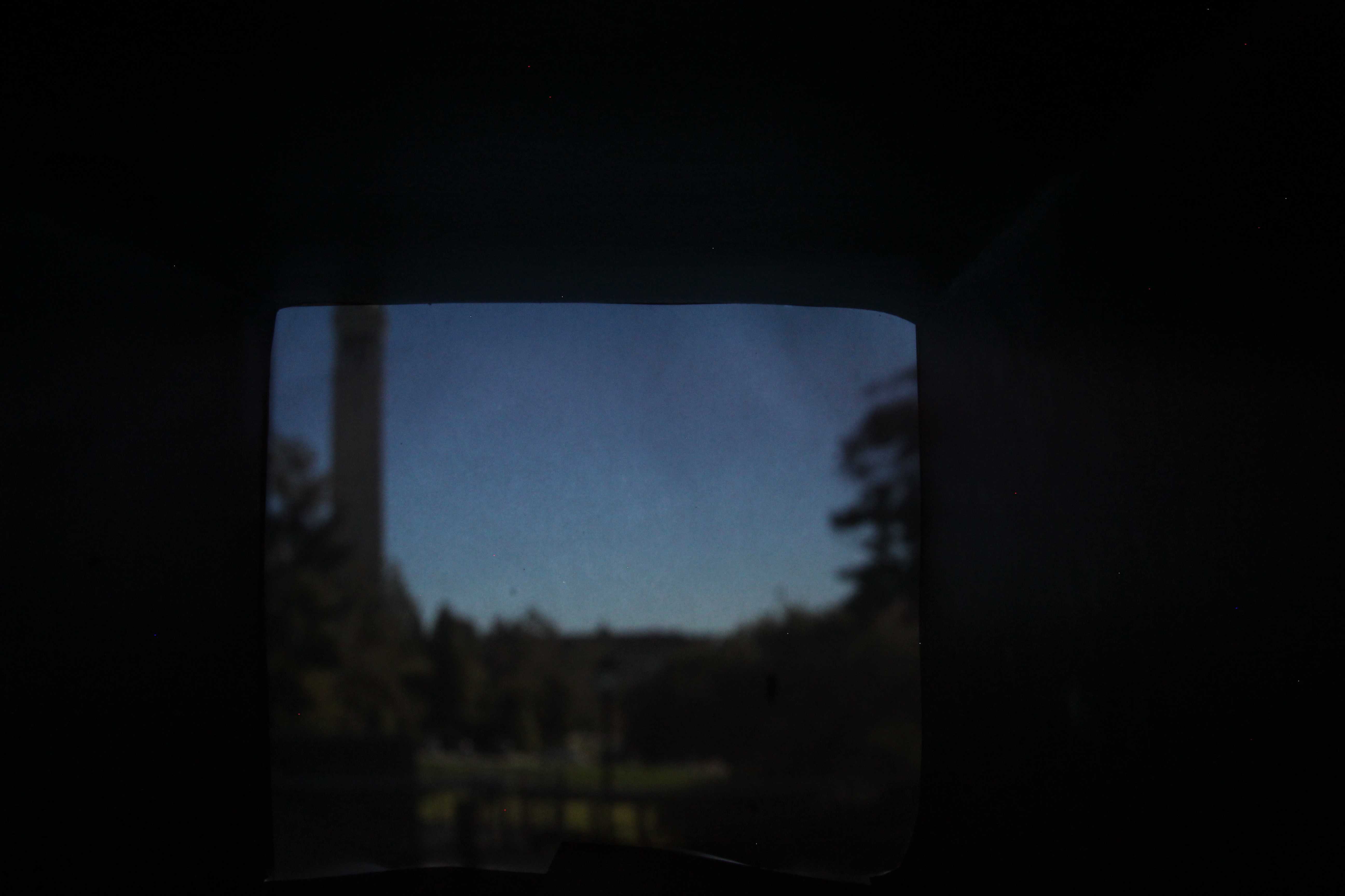
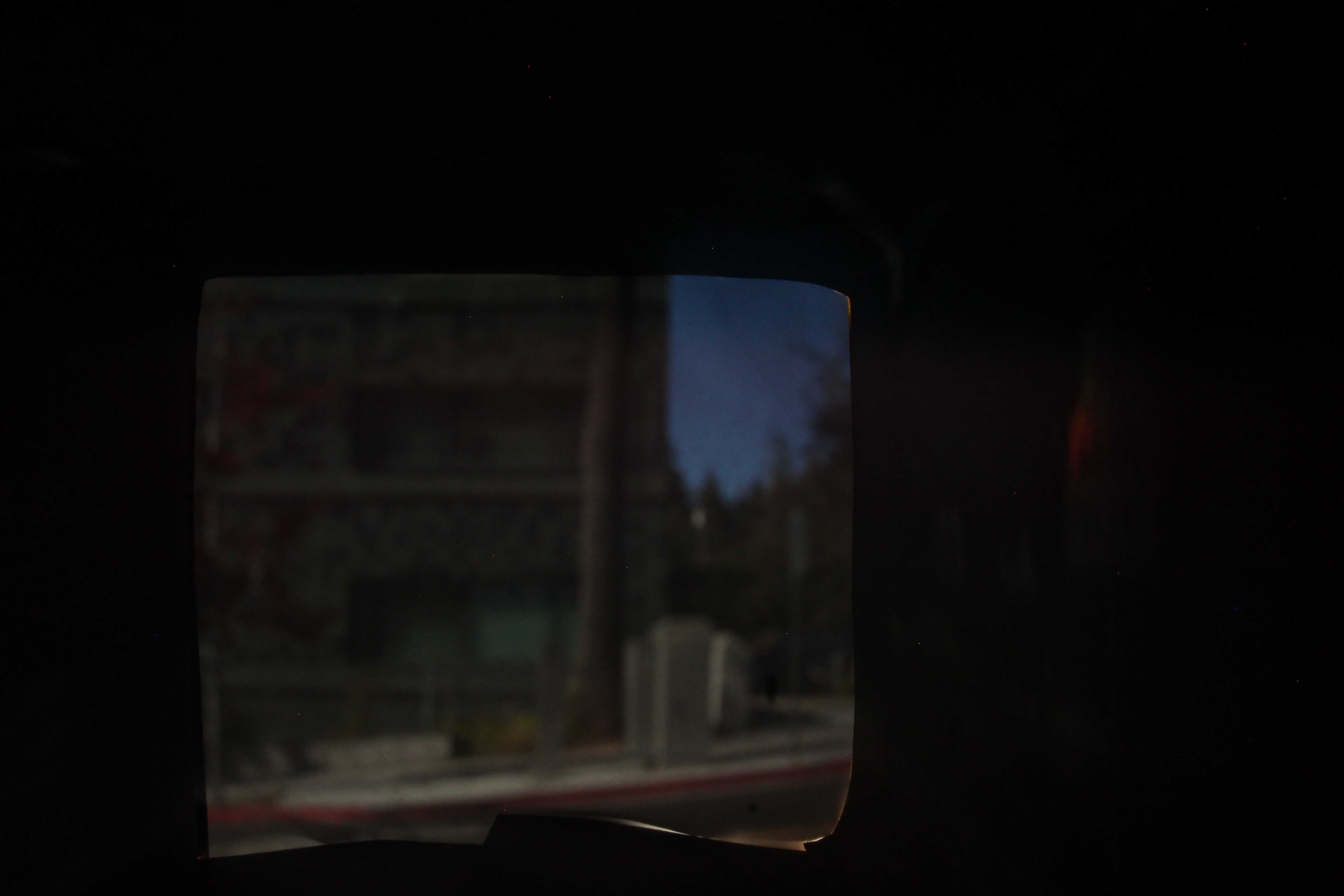
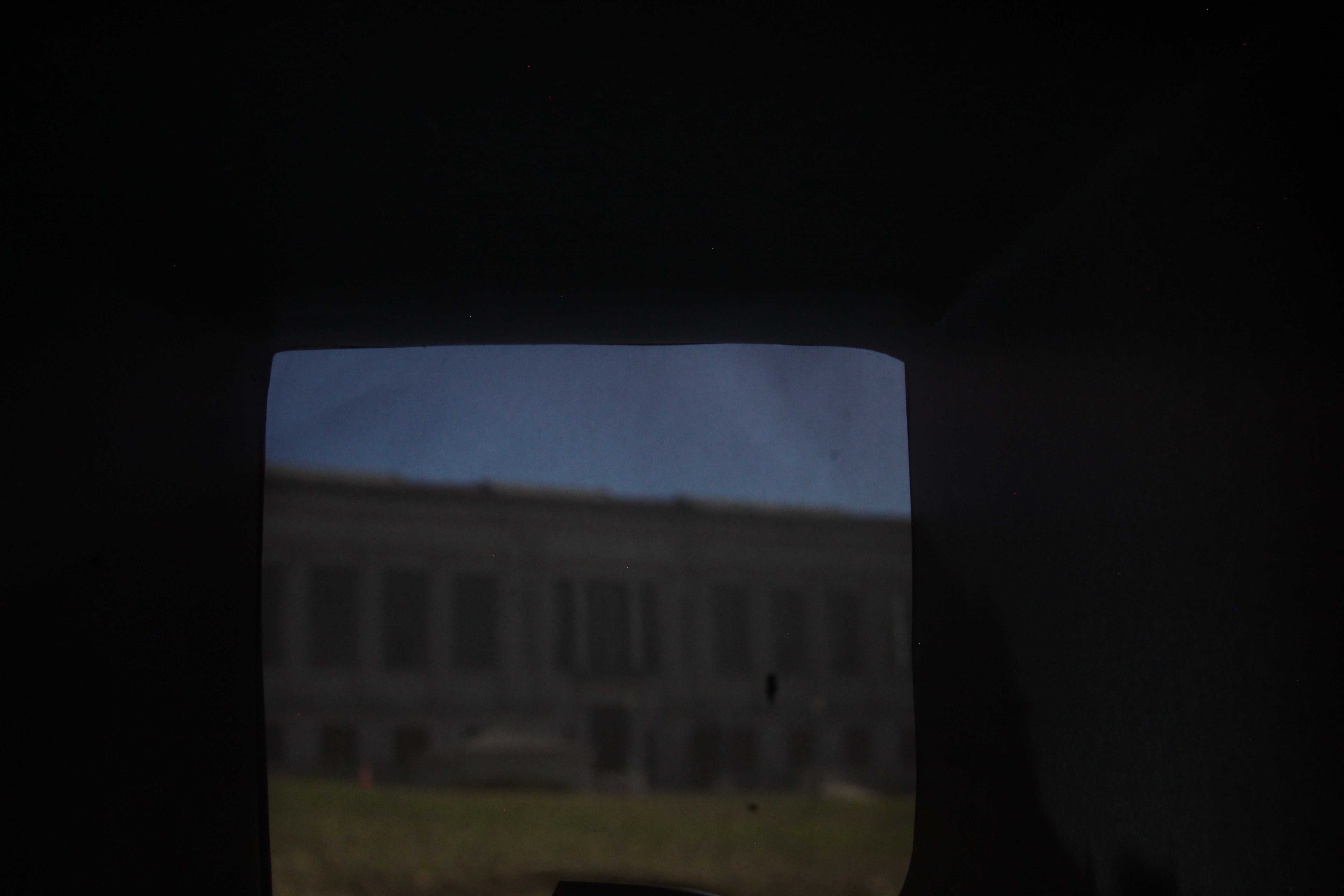
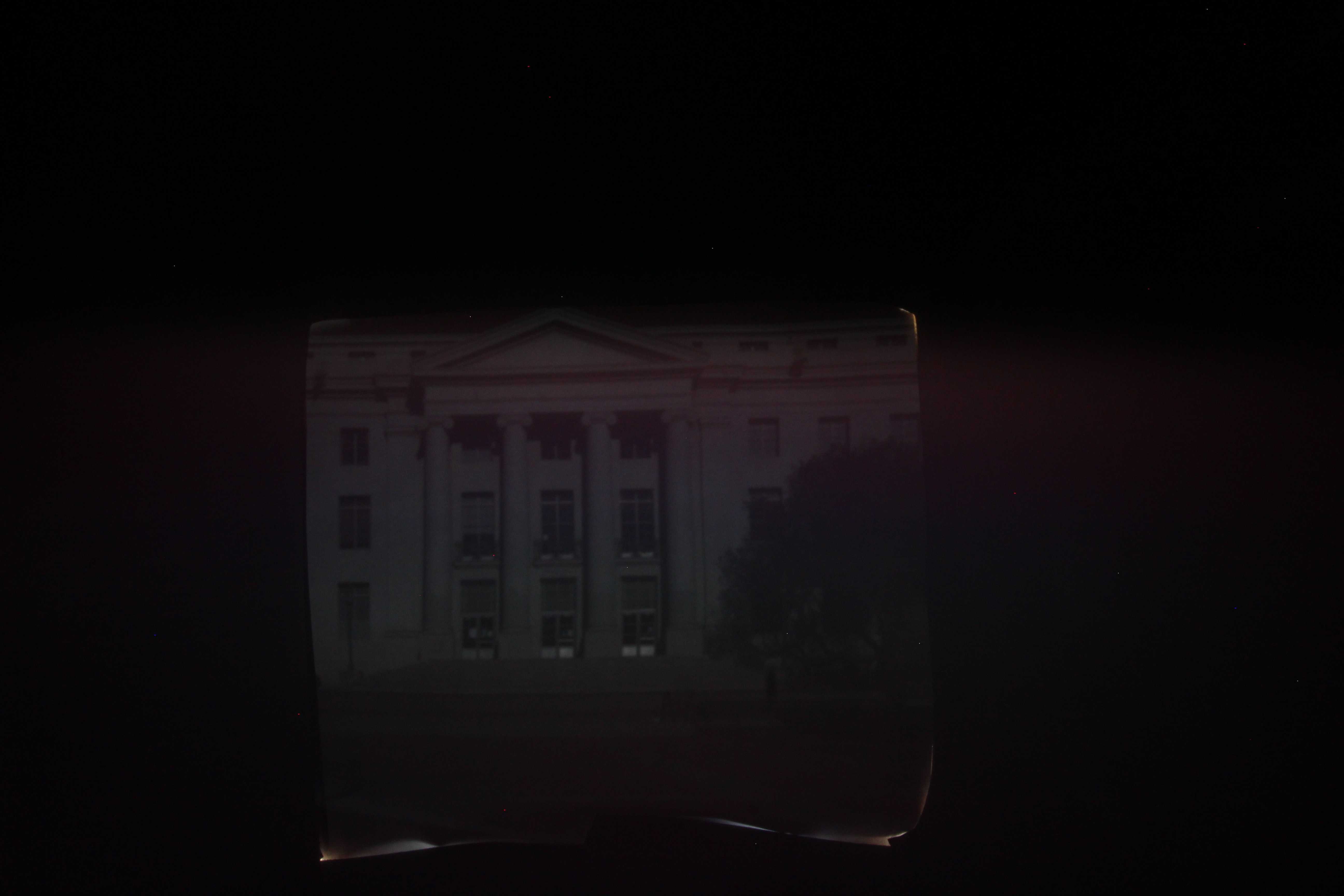
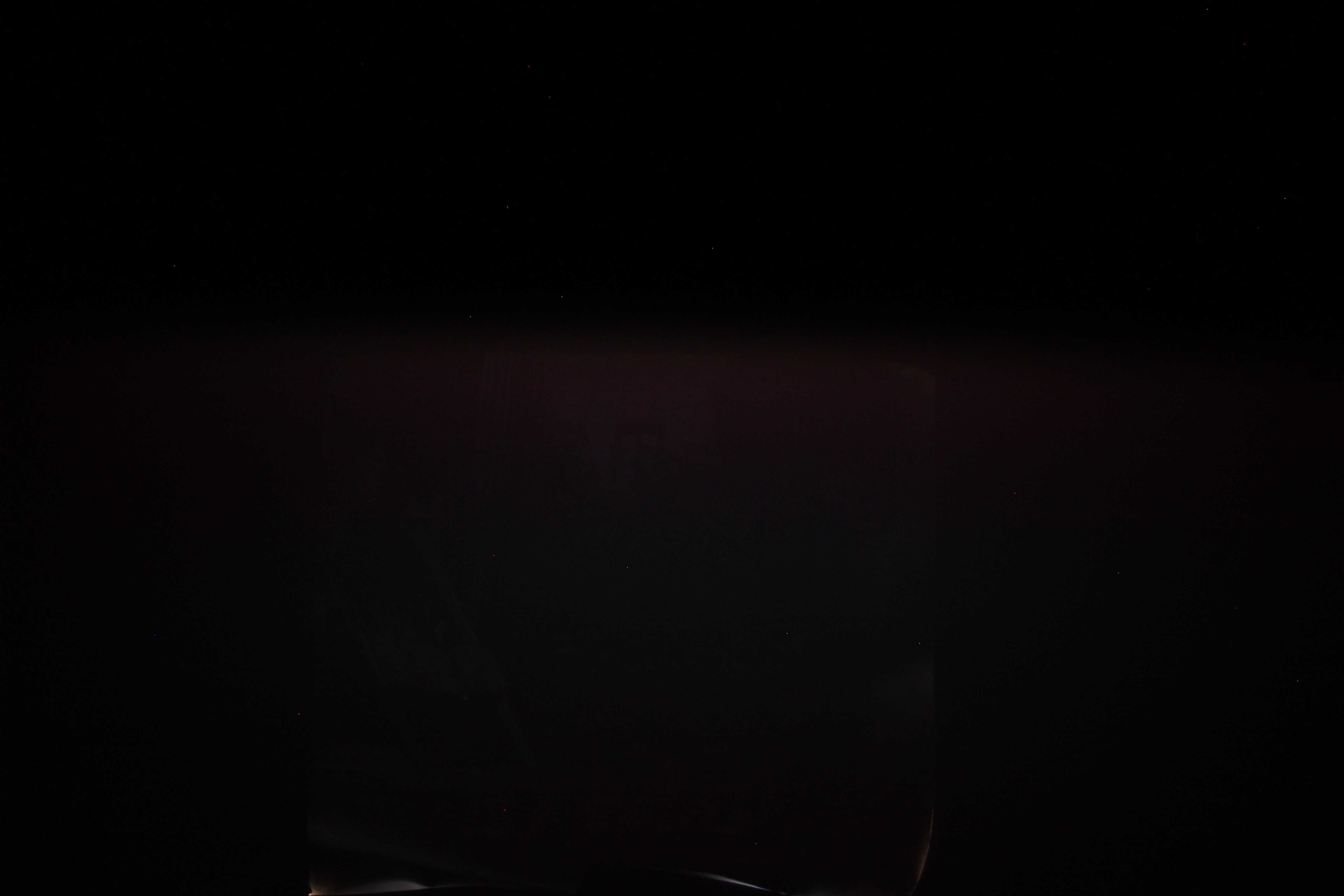
Width: 5 mm
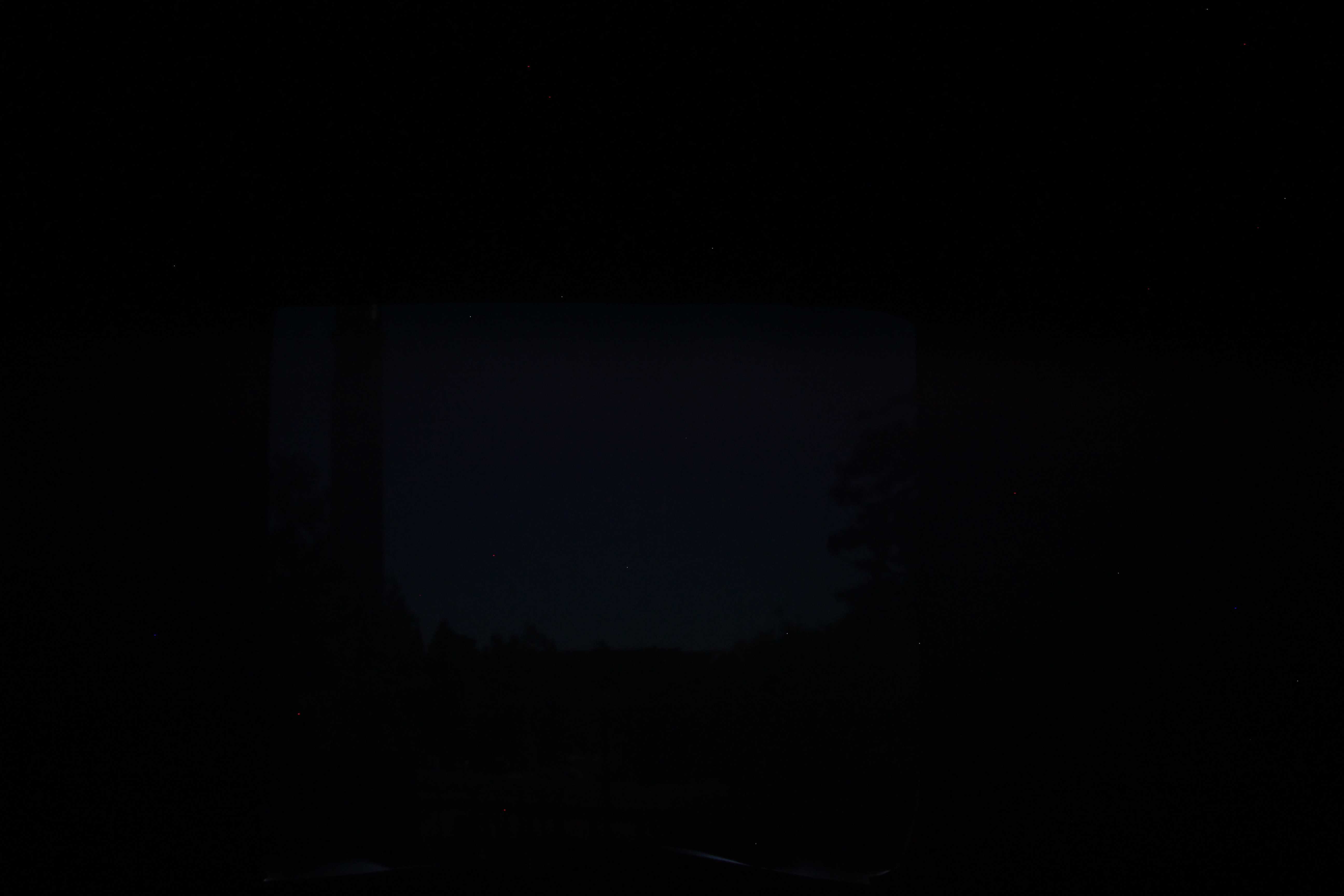
Width: 3 mm
Width: 1 mm

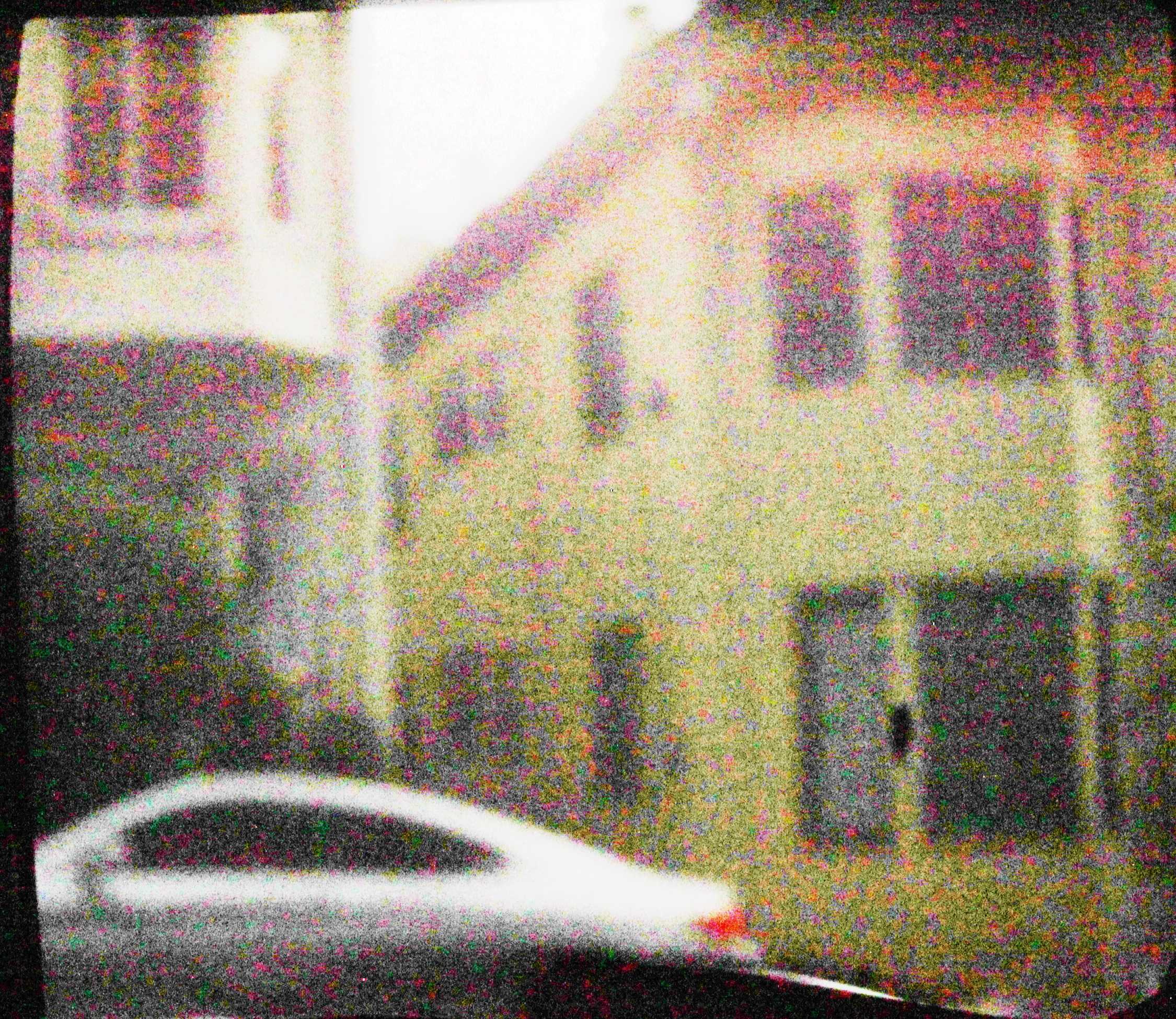
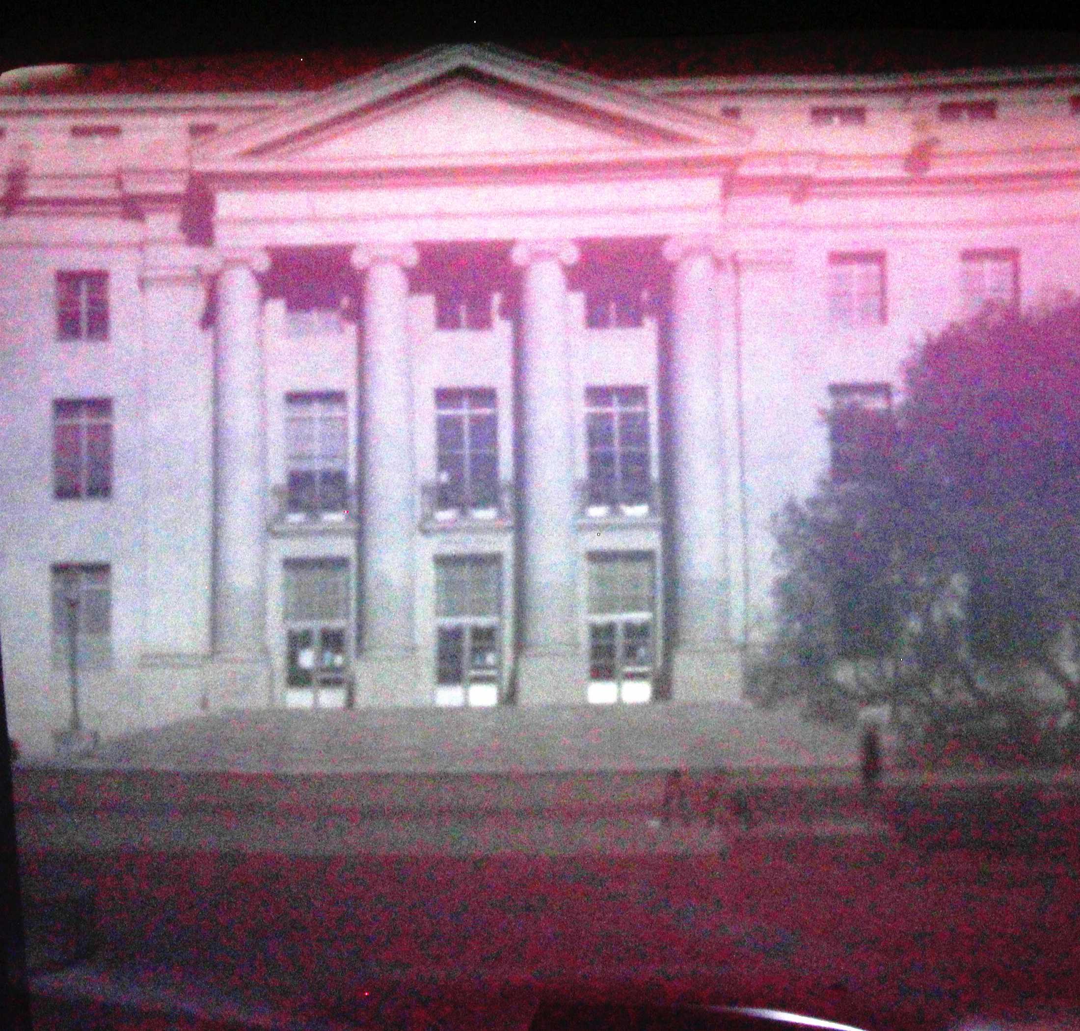
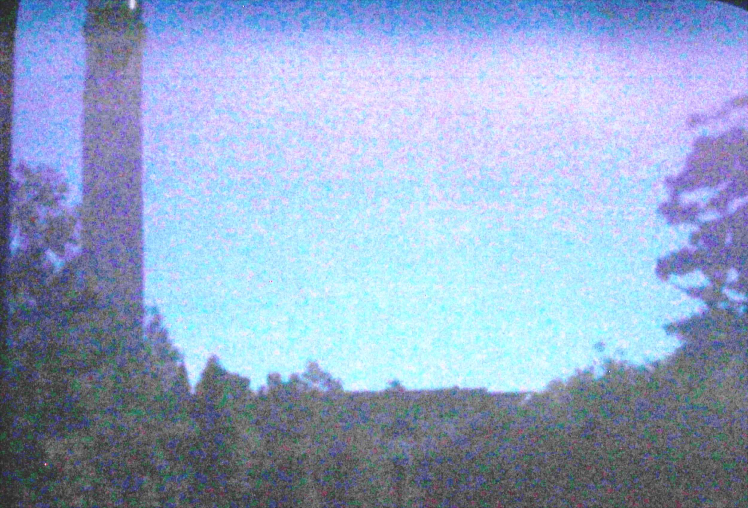
How did the pinhole size affect the image output? Basically until between an open hole with no pinhole to a 3mm pinohole, the resolution continued to go up. However, every pinhole size reduction resulted in a significant decrease in brightness. The decrease in brightness made it very difficult to discern the details in these darker images. Because of this brightness reduction, the 5mm ended up being the most effective. It actually produced a higher resolution than the open hole with no pinhole cover.
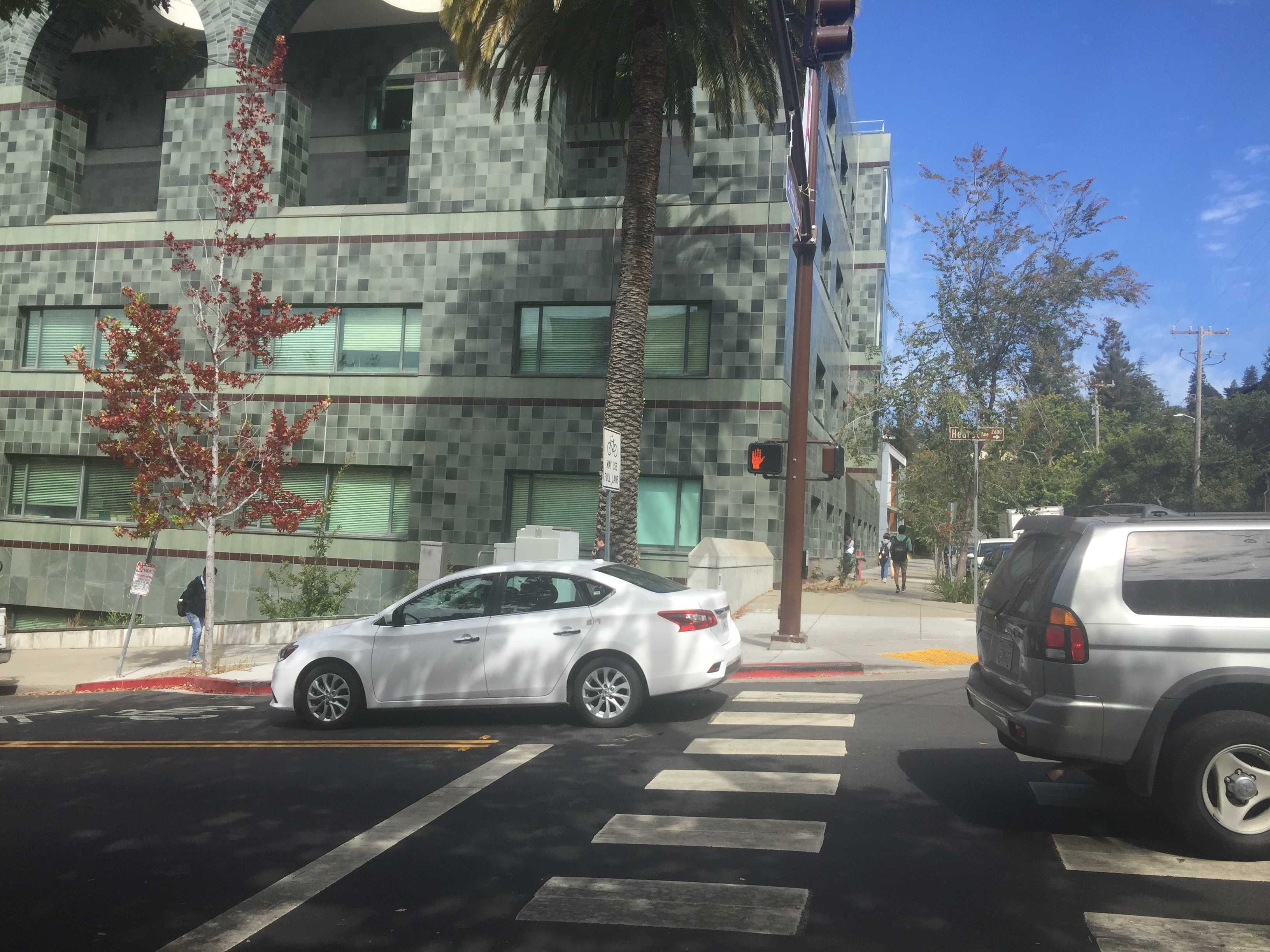
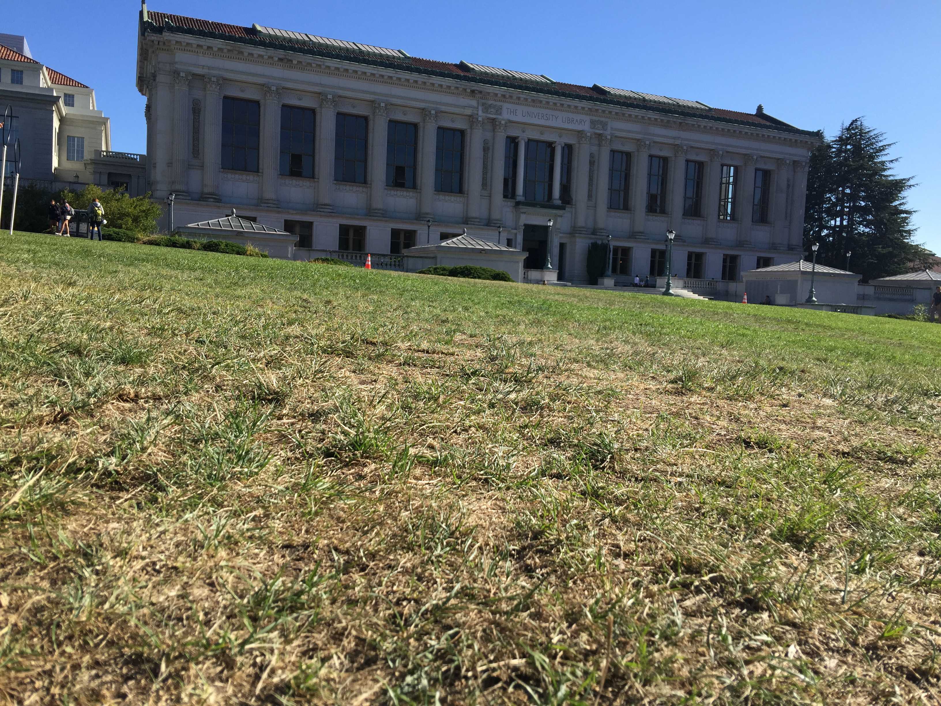

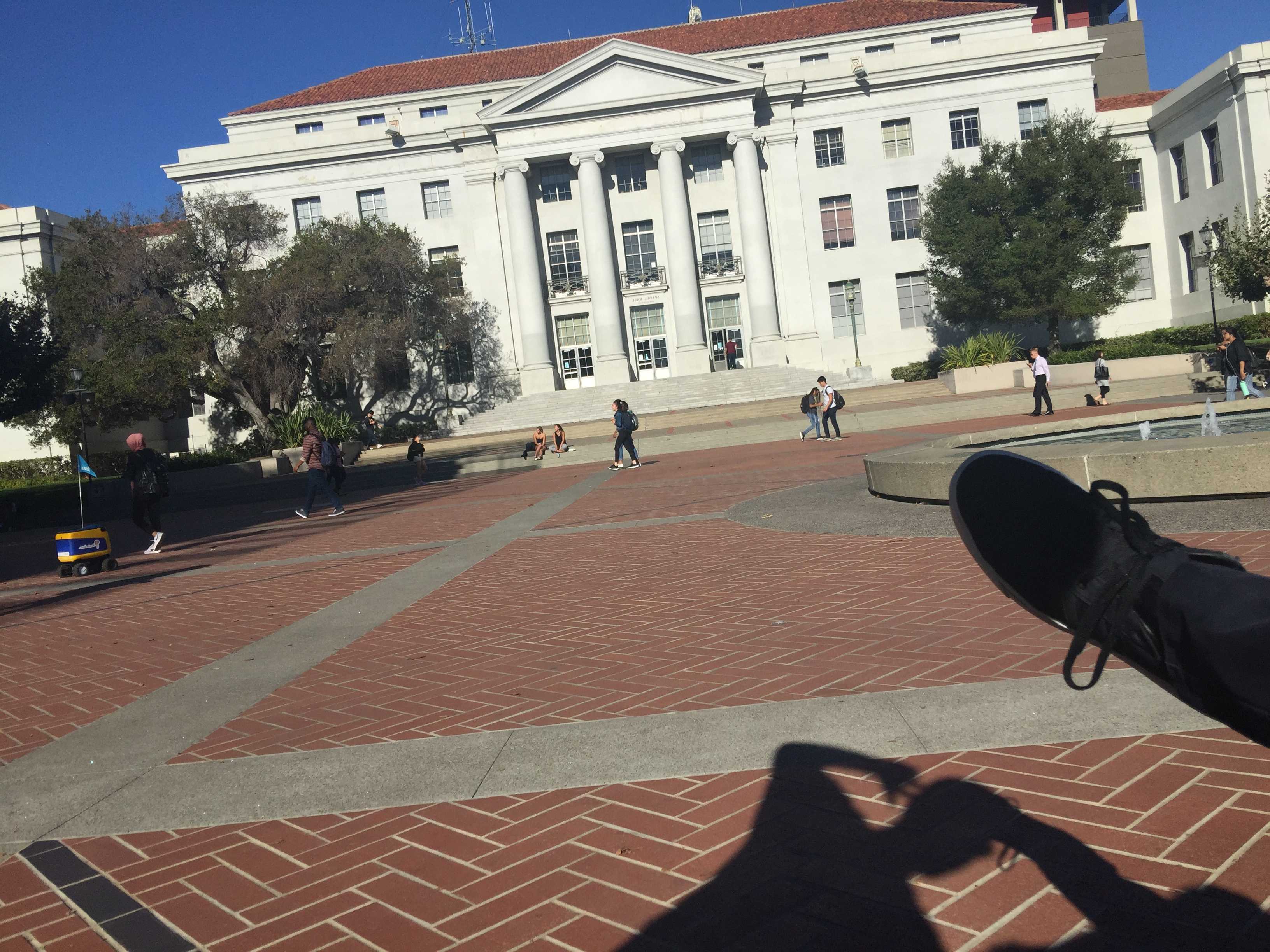
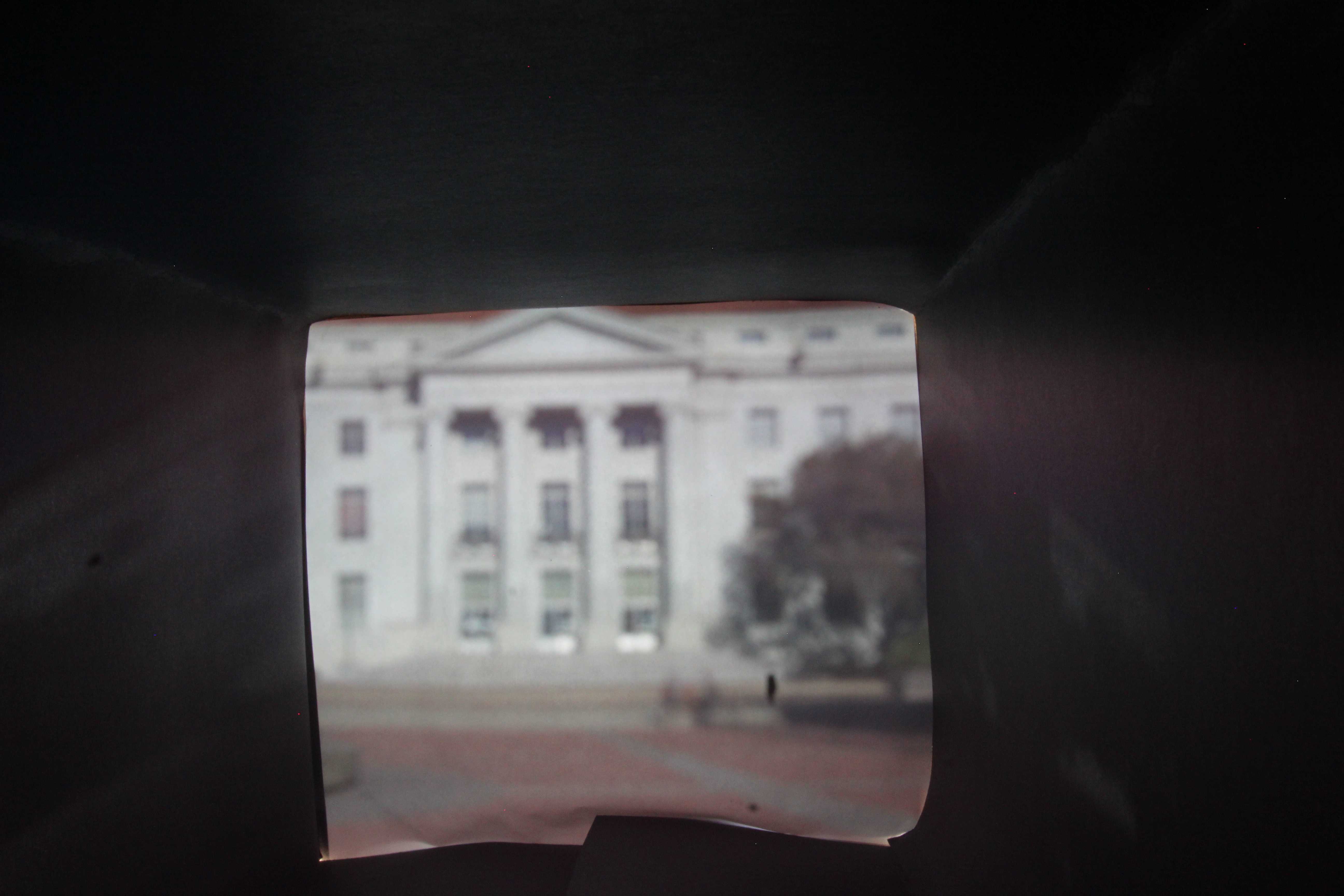
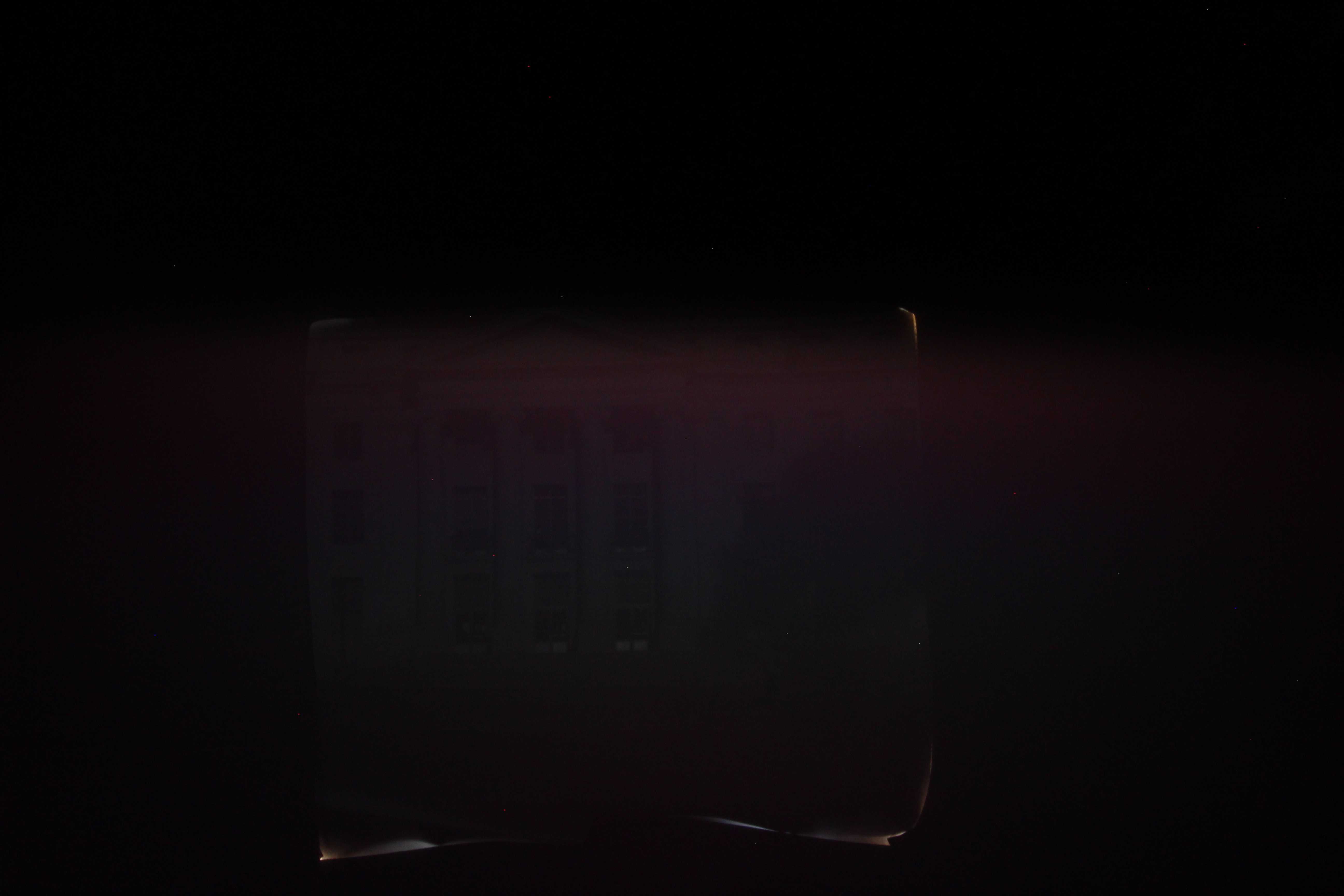
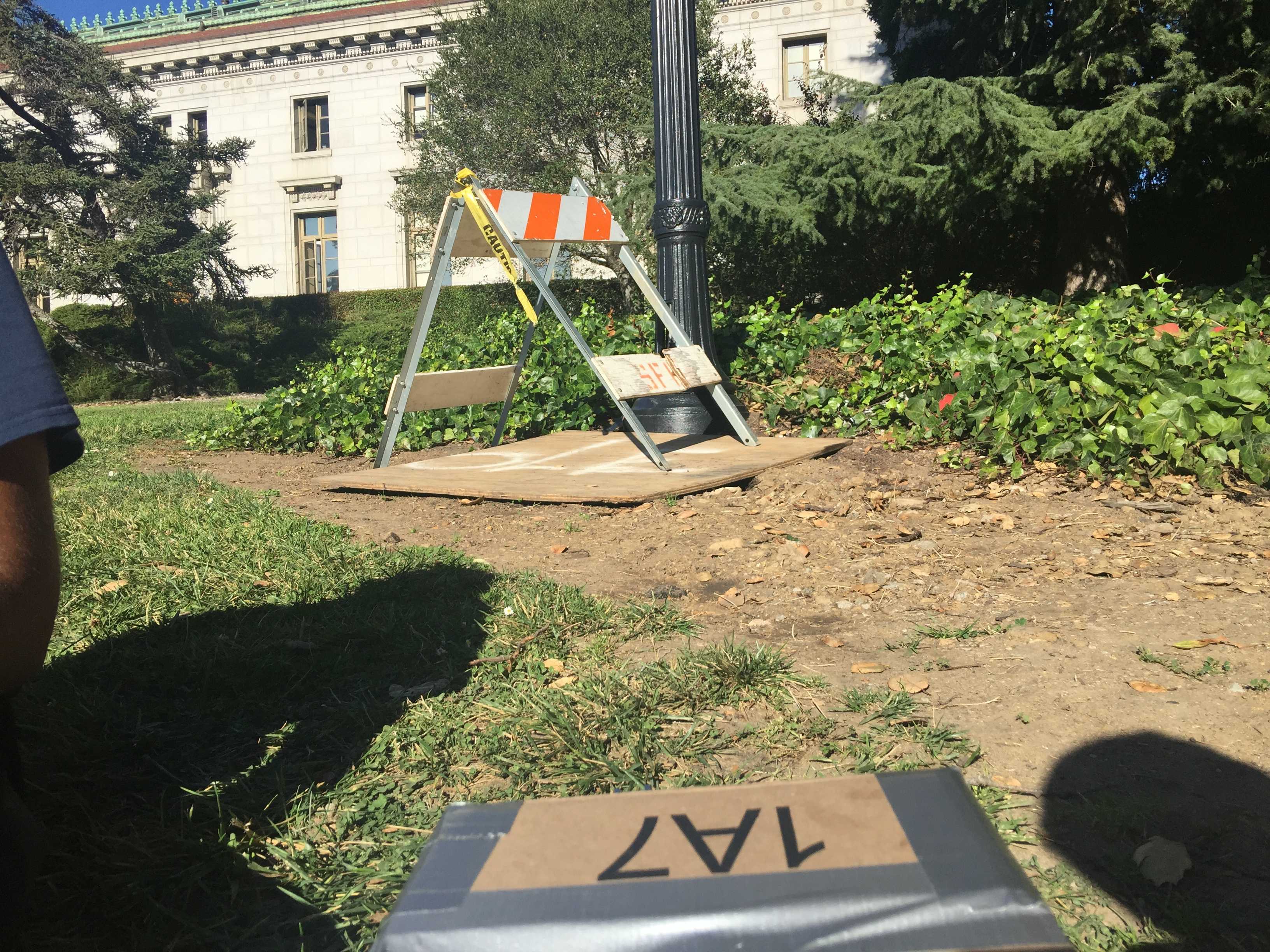
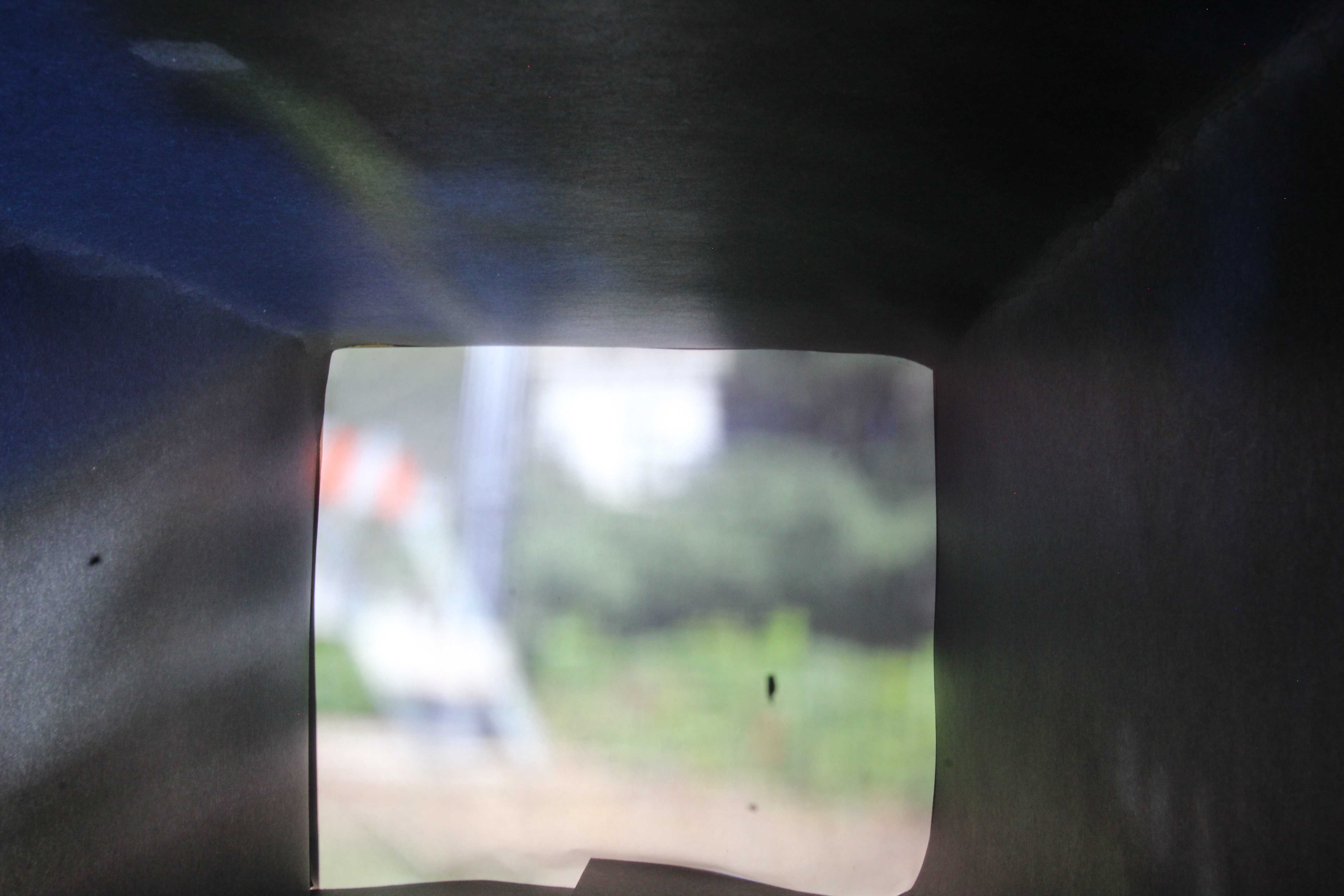
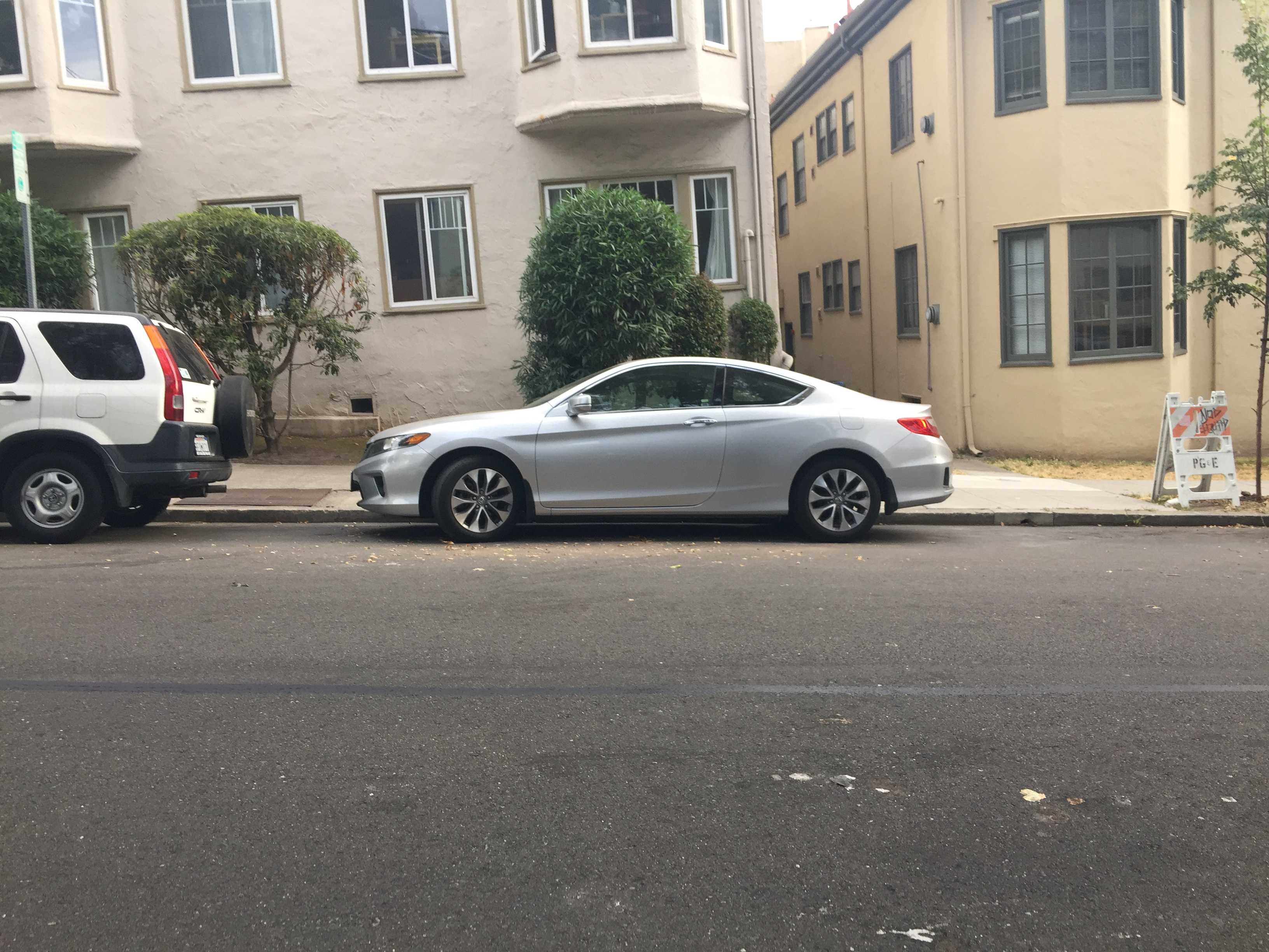
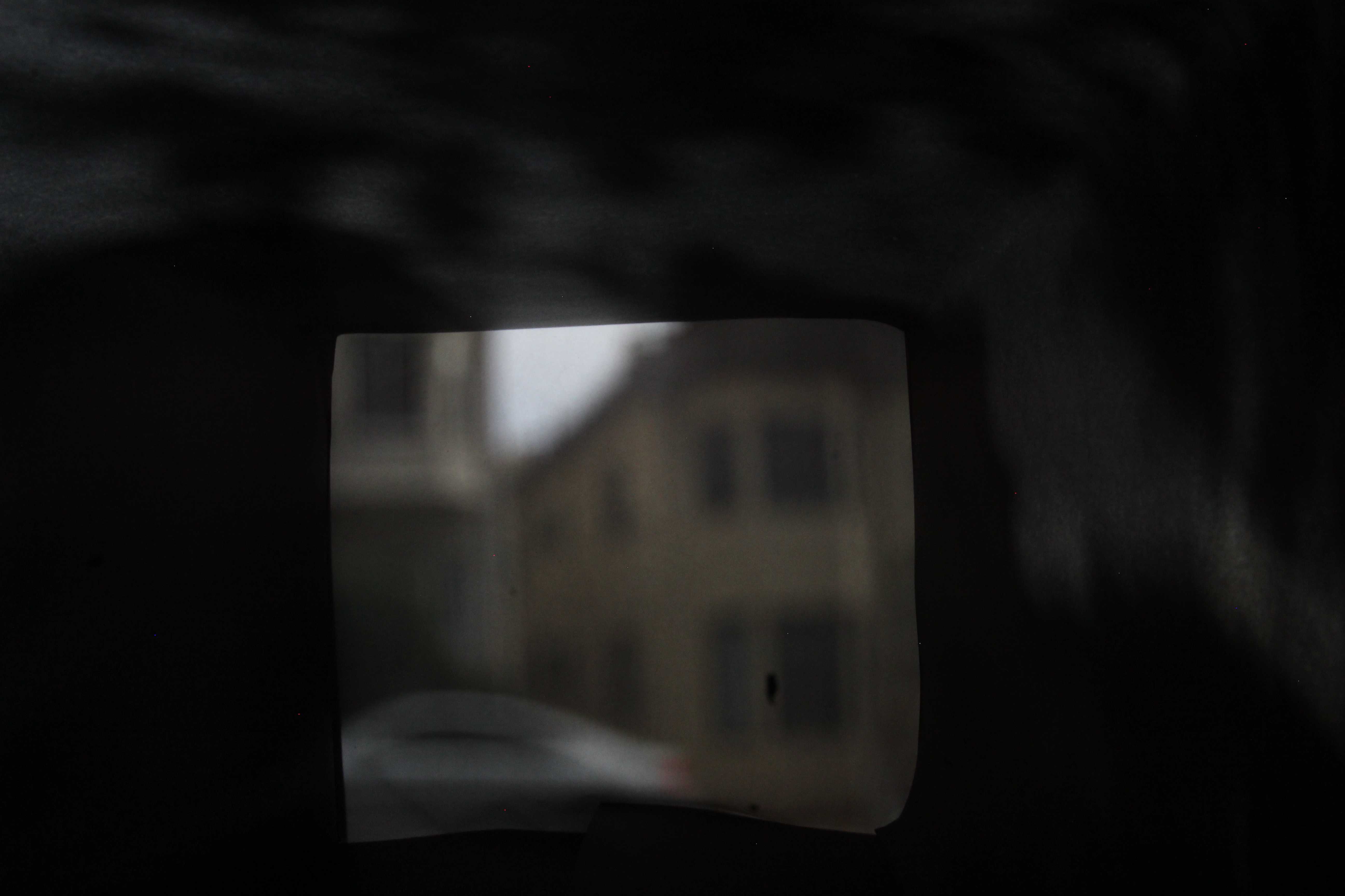


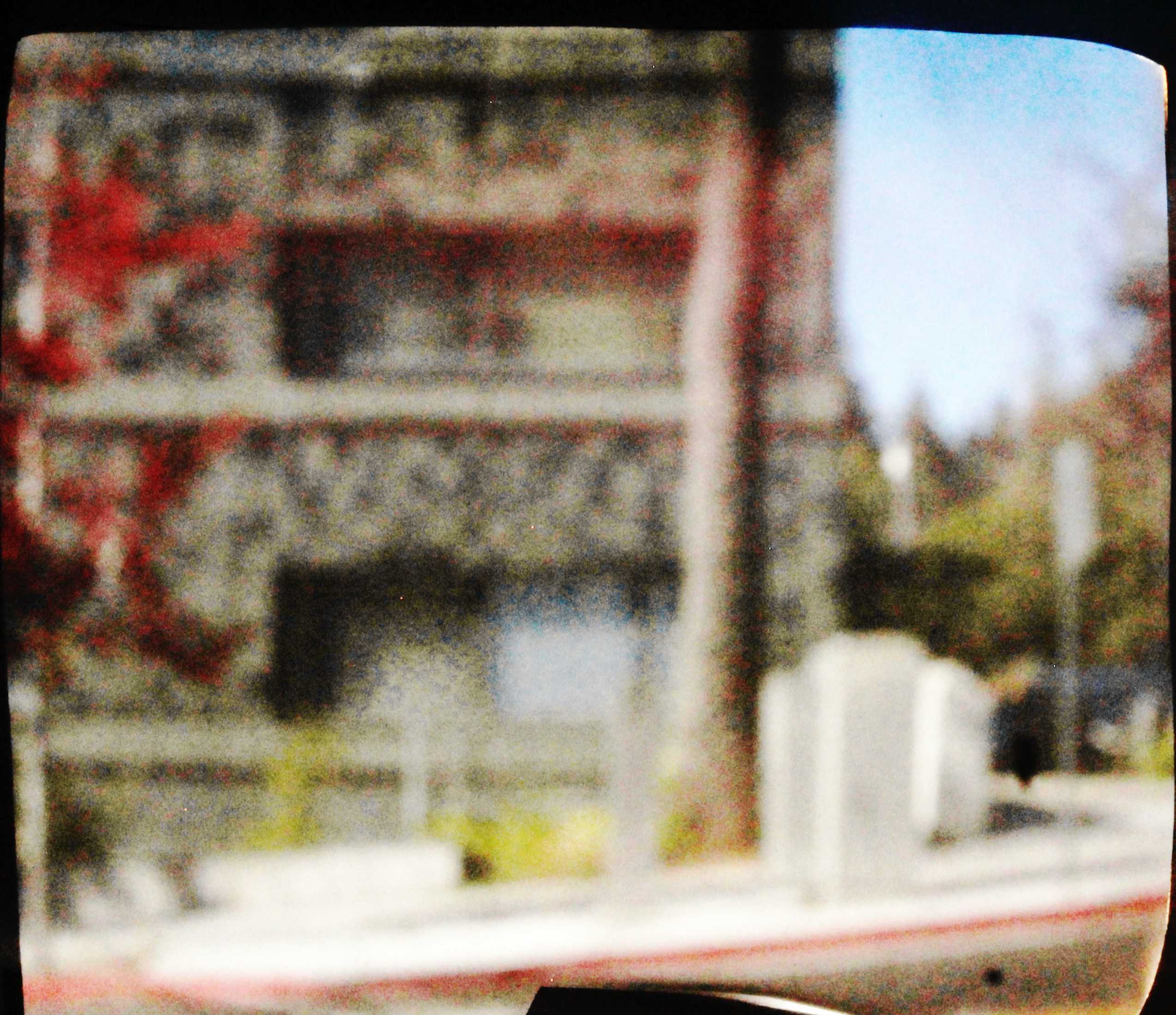
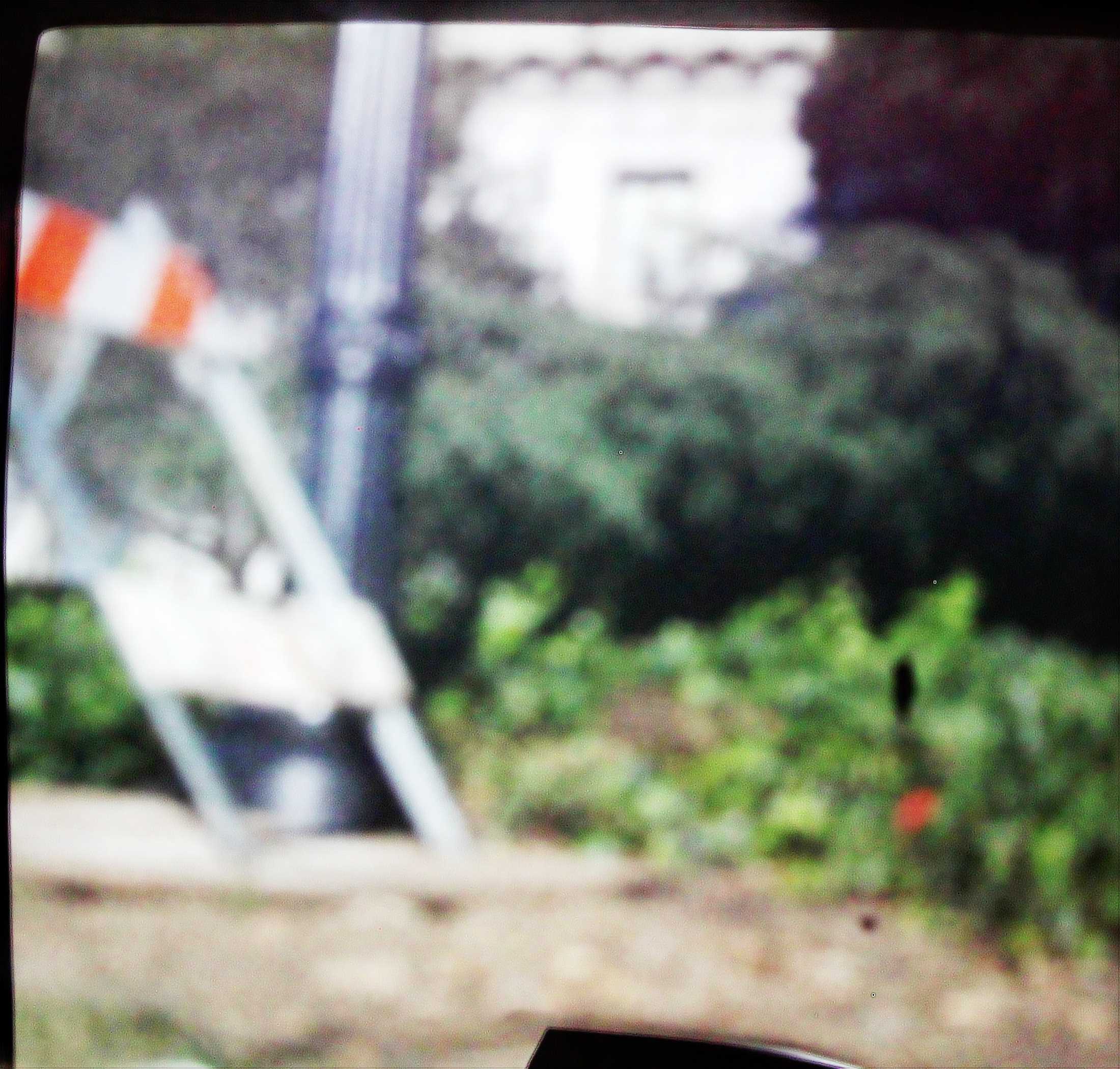
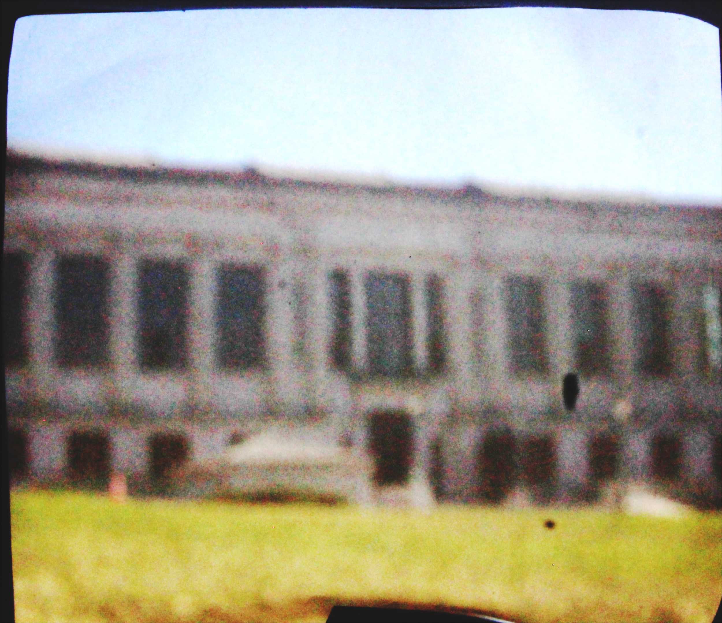
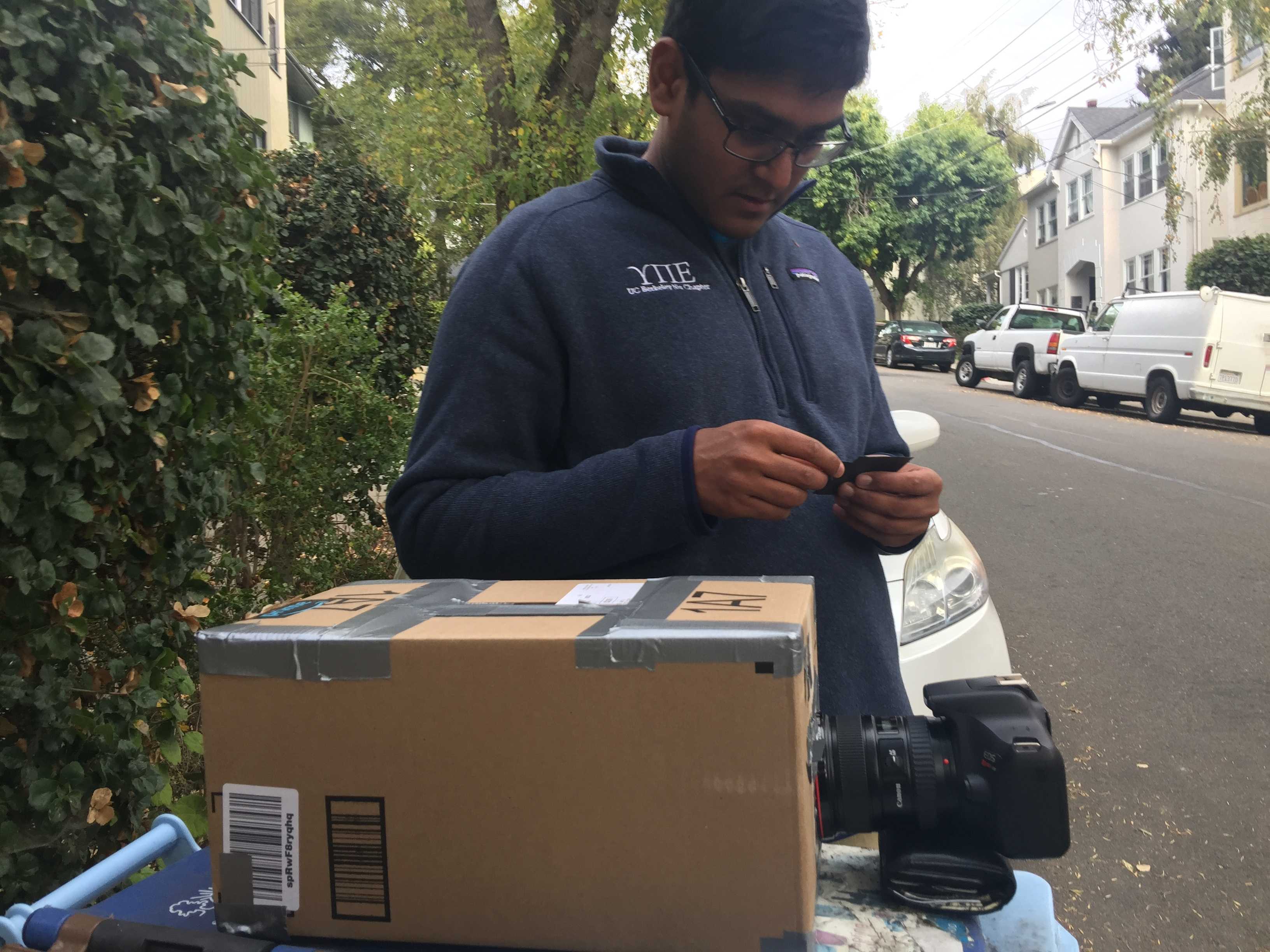
The first part of the solution is cropping. While most of the pinhole camera outputs were in the same cropping requirements, I did this manually because there were a few that were different. After cropping I flipped the image because the image projected in the back of the shoe box is upside down
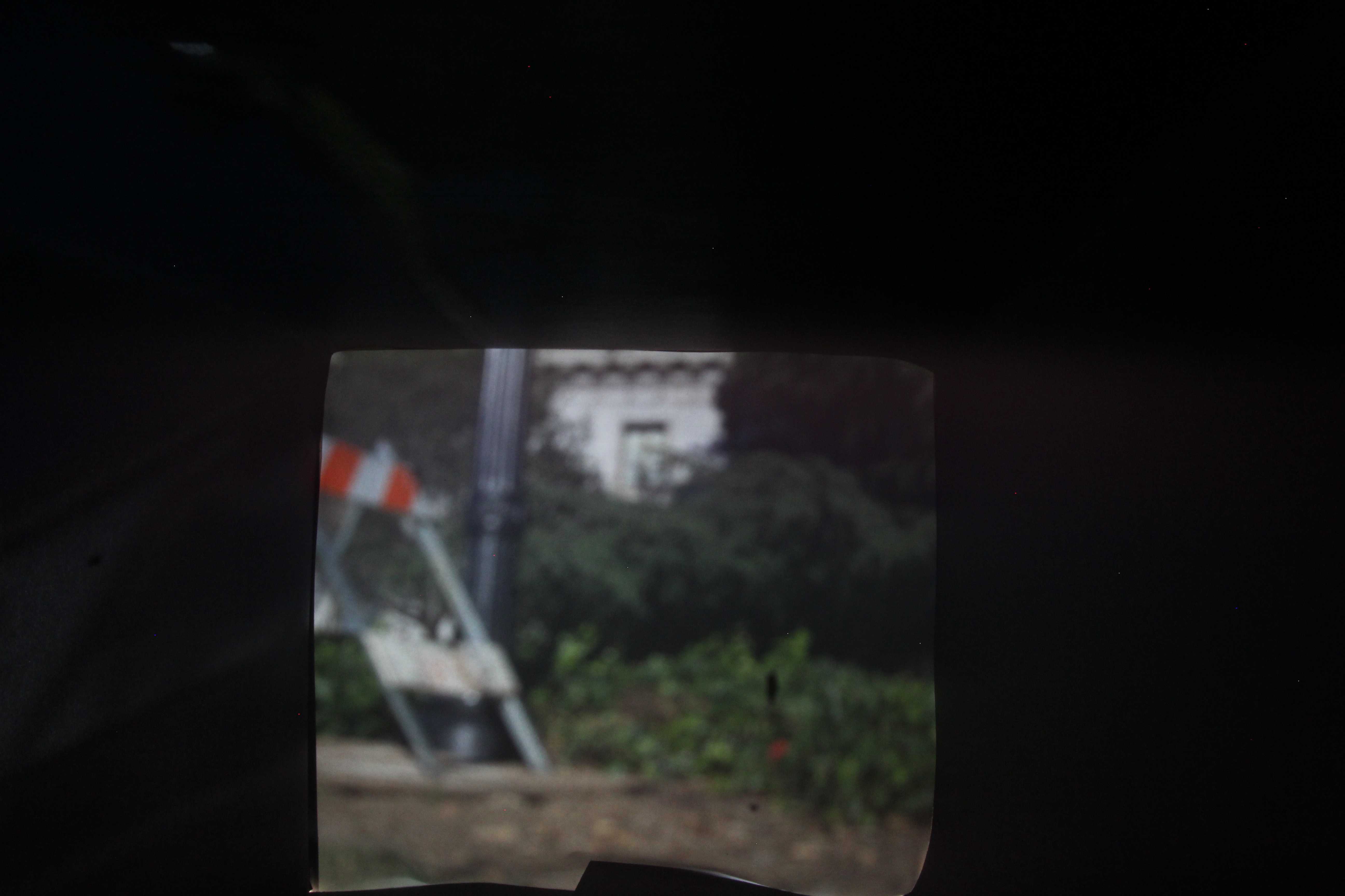
Second step is histogram equalization. I would use the cropped area and use skimage to distribute the pixel intensity uniformly from 0 to 255. This is necessary because the images are generally dark and centered in the bottom side of the spectrum. Histogram equalization would make it possible to discern details that were previously not visible. Sometimes the brightness would be too low as it was often sunny outside so I increased the brightness of these images.
Final step: denoising and sharpening. For denoising I used some of the traditional techniques available. I was familiar with adaptive median filtering but I found other denoising algorithms on skimage: wavelet denoising and bilateral denoising that were far more effective. For the sharpening for the image, I applied a laplacian filter over the image, scaled it by a tuned parameter, and then added it to the original image. Below is an example of the effect of denoising. The details are not very apparent but it makes a larger difference at lower resolutions.