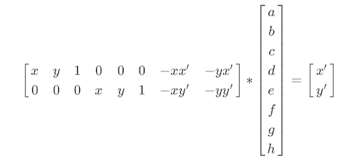
For this project, we first obtained photos (either via camera or online) of two scenes, with a 40% to 70% overlap between the views. From there, we calculated the parameters of a transformation between the two images, called a homography. We proceeded to do this by using the following equation to solve A * h = b, given pairs of corresponding points (x, y) and (x', y'):
We then proceeded, knowing the aforementioned homography, to warp one image into another and rectify the image so the plane is frontal-parallel by warping to a square. We did this by defining a point correspondence from the first images and manually inputting a point correspondence of a square as the second points. We then proceeded with the warp as indicated by the equation above. Finally, we used a weighted average combined with the warping technique to create the three image mosiacs shown below. As a bonus, the last image shows that image blending does not work as well when there is a disjoint part of the image, which is responsible for the unseemly cutoff when blended.
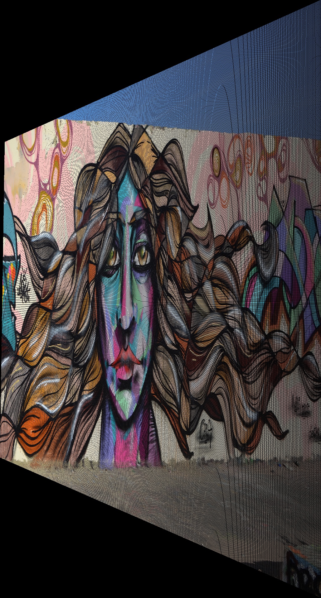
Input Image #1 - Warping Entire Mural to Square (Online)

Rectified Image #1
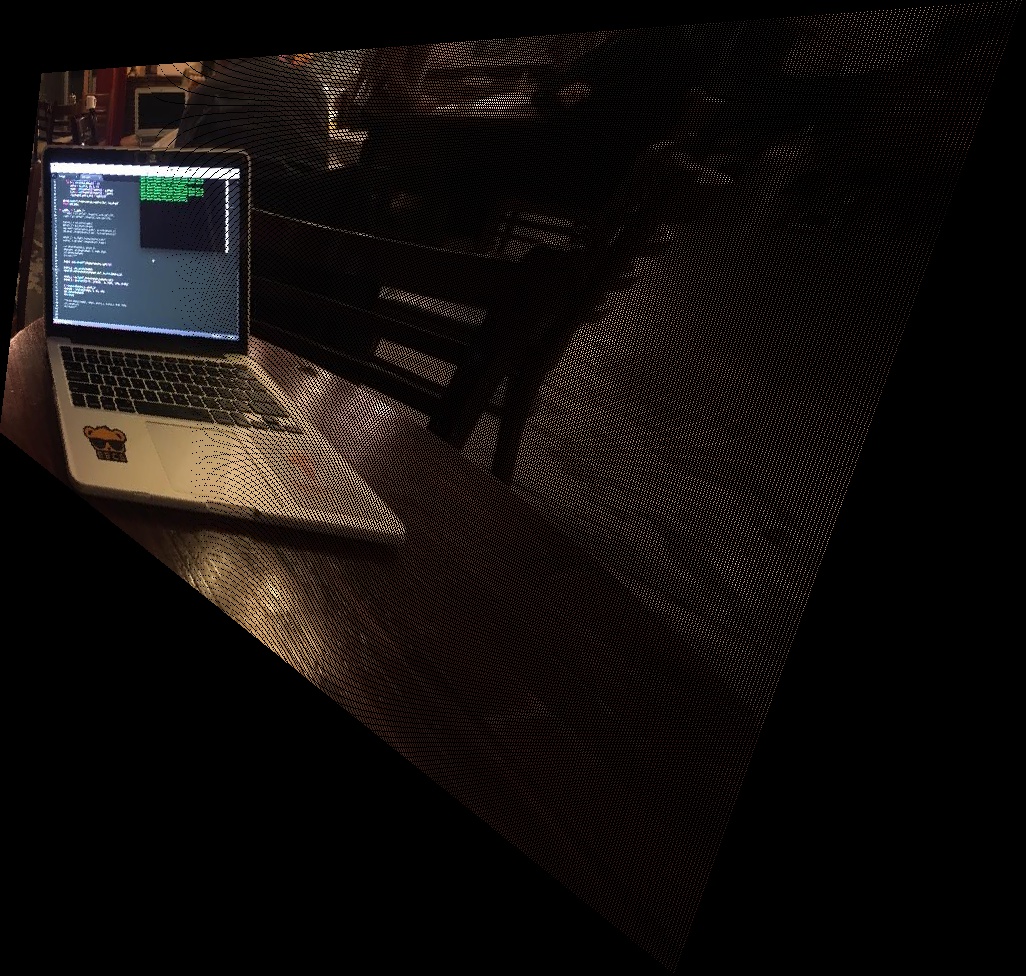
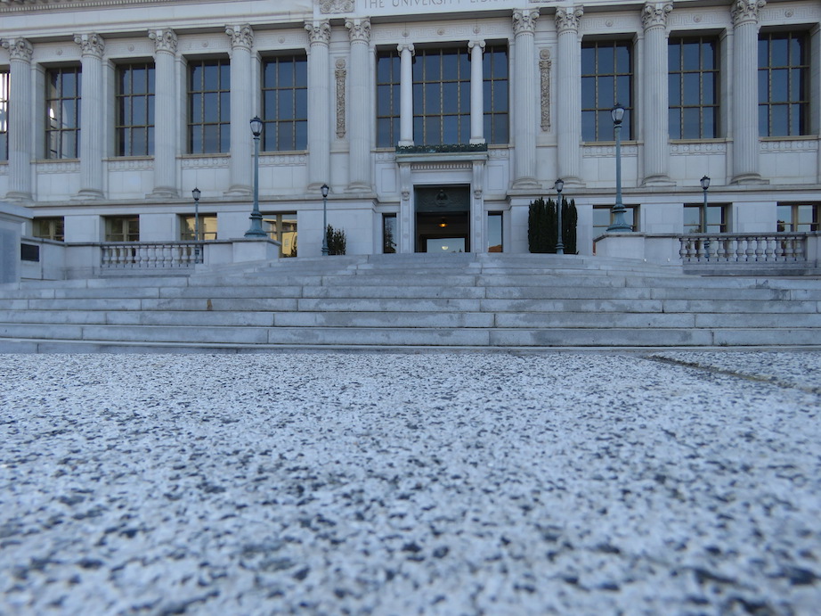
Input Image #2 - Warping only Computer Screen to Square (My Camera)

Rectified Image #2
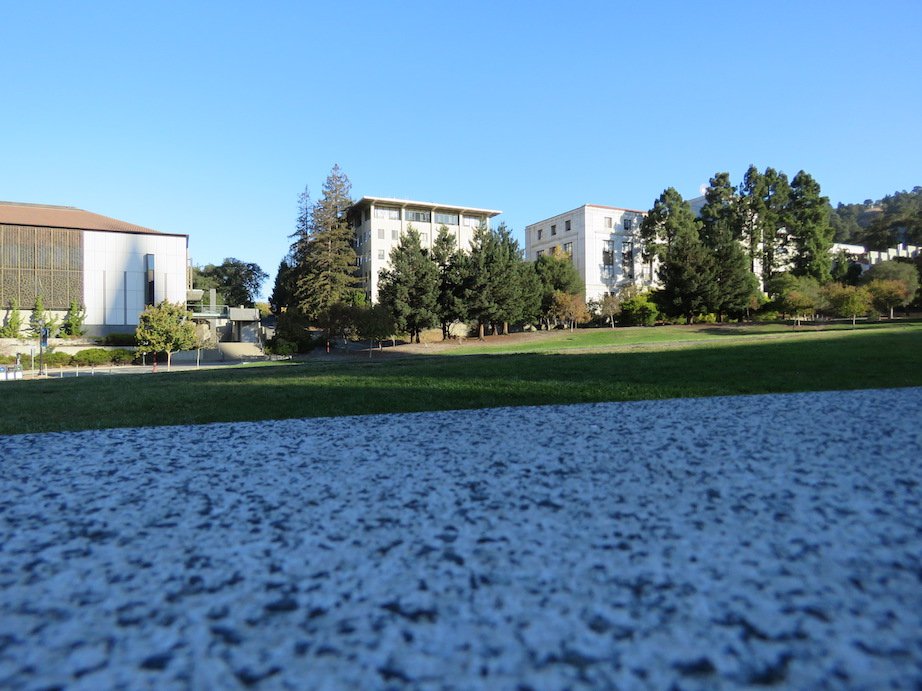
Input Image #1a (My Camera)
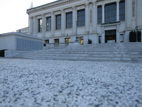
Input Image #1b (My Camera)

Mosaic Image #1
Input Image #2a (My Camera)
Input Image #2b (My Camera)

Mosaic Image #1
Input Image #3a (Online) - See explanation for unseemly line cutoff

Input Image #3b (Online)

Mosaic Image #3
Input Images Showcased Below for Reference
Input Image #1a (My Camera)
Input Image #1b (My Camera)
Input Image #2a (My Camera)
Input Image #2b (My Camera)
Input Image #3a (Online)
Input Image #3b (Online)
Input Image #4a (Bonus Online)

Input Image #4b (Bonus Online)

First, I used a Harris corner and Harris interest point detector. I limited the number of Harris corners/feature points detected by performing Adaptive Non-Maximal Suppression (ANMS). In doing so, we are able to keep only the strongest interest points, but also ensure that they are spread throughout the image. This works in practice to ensure that one selects only feature points that have a large radius around them before reaching another similarly strong feature point. In other words, you ensure the radii for selected features fulfill the following equation:

We show a few results below. Not all results are displayed for purposes of brevity.
Naive Harris without ANMS - Input Image #1a
Harris Point Selection with ANMS - Input Image #1a
Harris Point Selection with ANMS - Input Image #3a (Online)
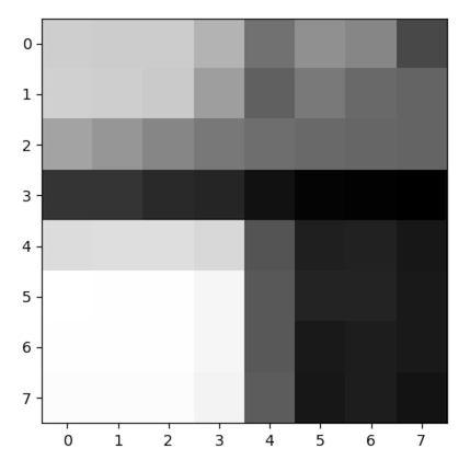
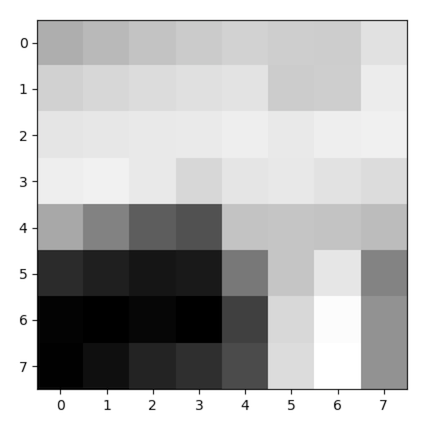
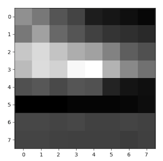
Here, a bias/gain normalized sampling of a local patch (8x8) from a higher pyramid level (40x40) is used to create a vector feature descriptor for each interest point. These descriptors are used for feature matching. See example from a few interest points below:
Feature Descriptor from Input Image #1a (My Camera)
Feature Descriptor from Input Image #2a (My Camera)
Feature Descriptor from Input Image #4a (Online)
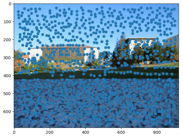
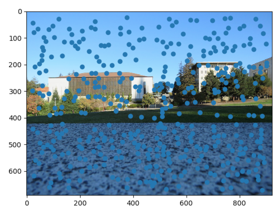
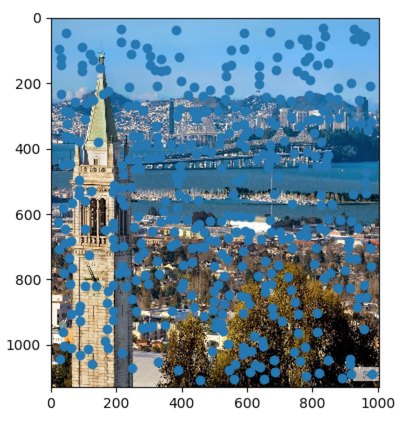
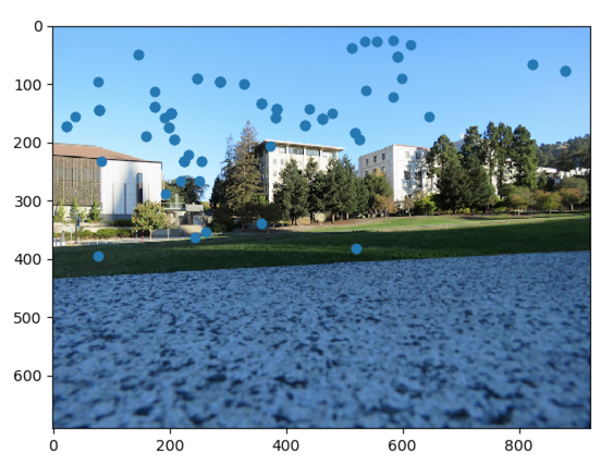
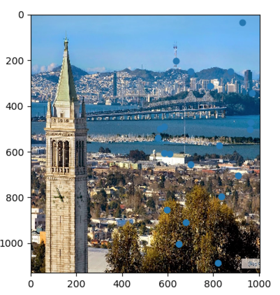
Here, the goal is to find pairs of feature that look similar and thus are likely to be good matches between the two images we want to stitch together. We can easily compute the similarity between two interest points by taking the SSD between their two descriptor vectors. Lowe's paper found that the difference between first nearest neighbors and second nearest neighbors was a more accurate marker for matching than the absolute distances of the first nearest neighbors. Thus, in order to determine what a good match is, after running a simple nearest neighbors algorithm, the ratio between the first best match and second best match for each interest point in one image is compared to a threshold ratio based on the outlier distance. See results below (Look for the blue dots):
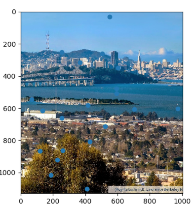
Match from Input Image #1a (My Camera)
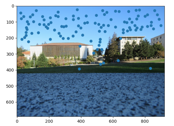
Match from Input Image #1b (My Camera)
Match from Input Image #2a (My Camera)
Match from Input Image #2b (My Camera)
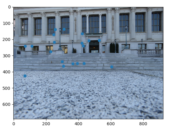
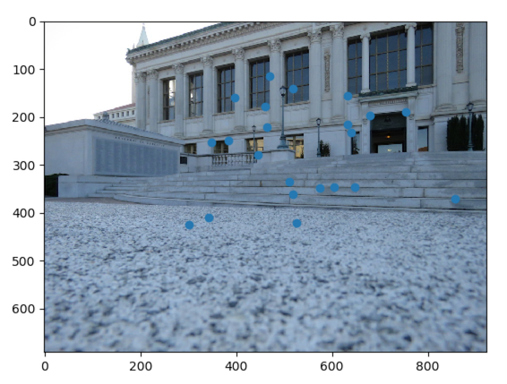
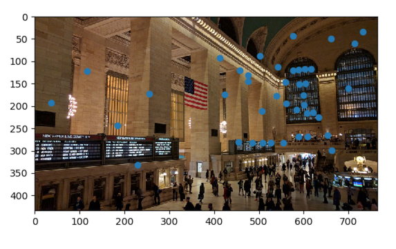
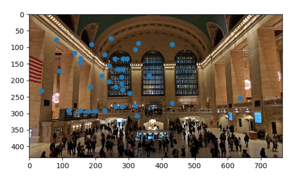
Match from Input Image #3a (Online)
Match from Input Image #3b (Online)
Match from Input Image #4a (Online)
Match from Input Image #4b (Online)
Over many iterations: one selects 4 random feature pairs. The homography H is computed exactly as in Part A of this project. Then, one computes inliers on all pairs of interest points, where SSD(pi', Hpi) is less than some threshold error. Then, after many iterations, one takes the iteration that generated the largest set of inliers, and re-computes the least squares H estimate on all of those inliers. As the only result here is a homography output, please see the code to verify completion.
Using the H computed from the automatically detected corresponding feature pairs, one can warp the images and stitch them together into mosaics. Below I will show the results of manual stitching (part A), except for the final image which is a for-fun bonus. Unfortunately, my auto-stitching does not work completely, but I have verified my homography and parts of my code are correct. Se lines 296-301 of harris.py for more information
Hand-Stitched Mosiac from Input Image #1 (My Camera)
Hand-Stitched Mosiac from Input Image #2 (My Camera)
Hand-Stitched Mosiac from Input Image #3 (My Camera)