CS194-26:
Image Manipulation and Computational Photography
Grace Park
SID: 3032341209
cs194-26-acd
Project 6: Image Warping and Mosaicing
Overview
In this project, multiple images will be warped and stitched together to create a panorama. First, the image will have to be taken where the position of the camera doesn't change in transition, but only in rotation. Then, homography matrix will be calculated using the corresponding points of the images and a warped image will be created. Then the images can be stitched together to create a panorama.
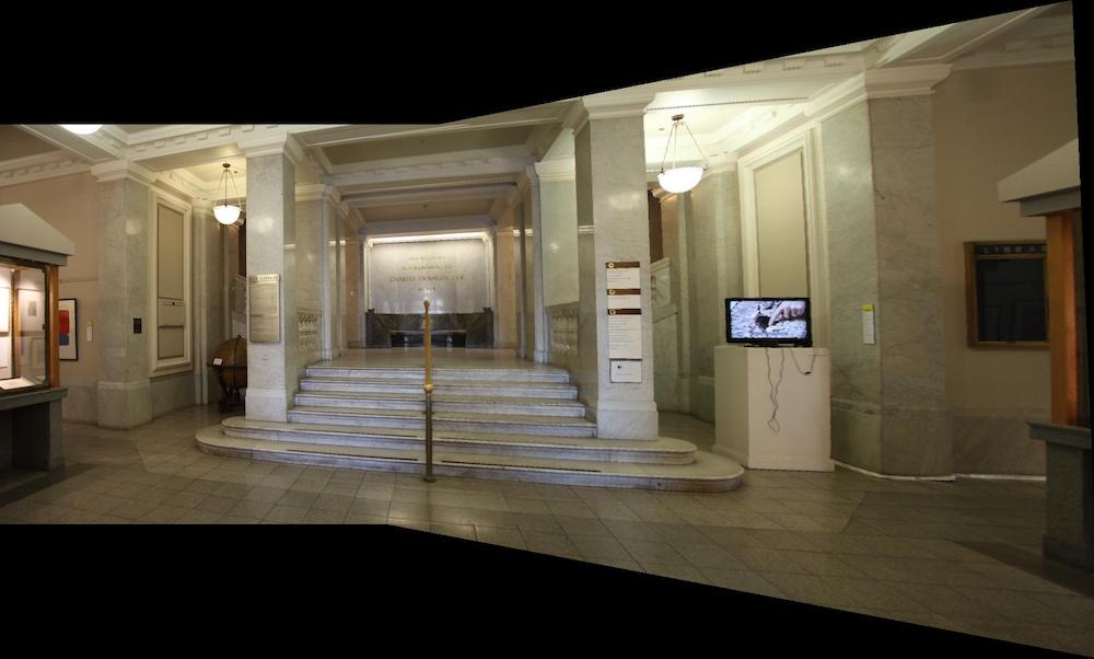
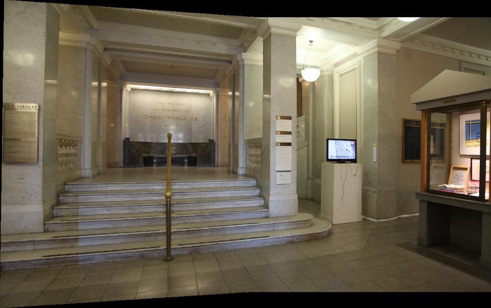
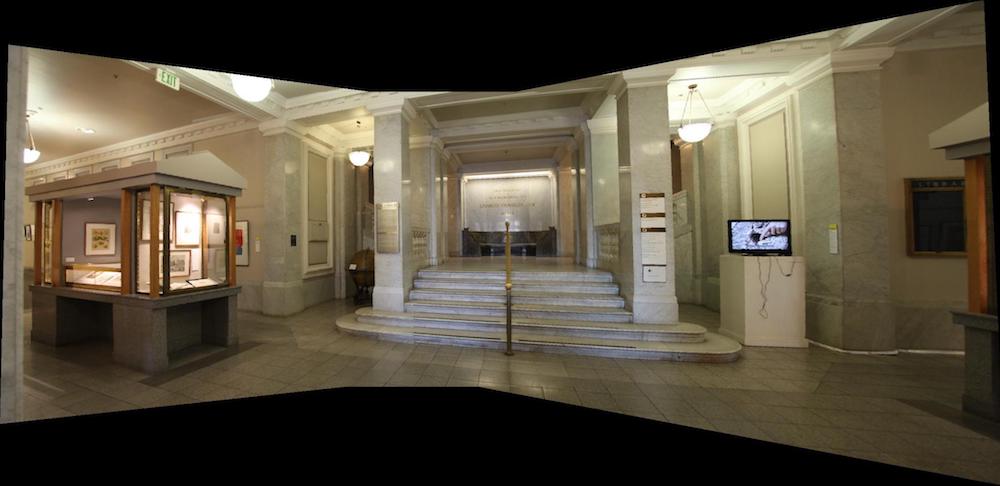
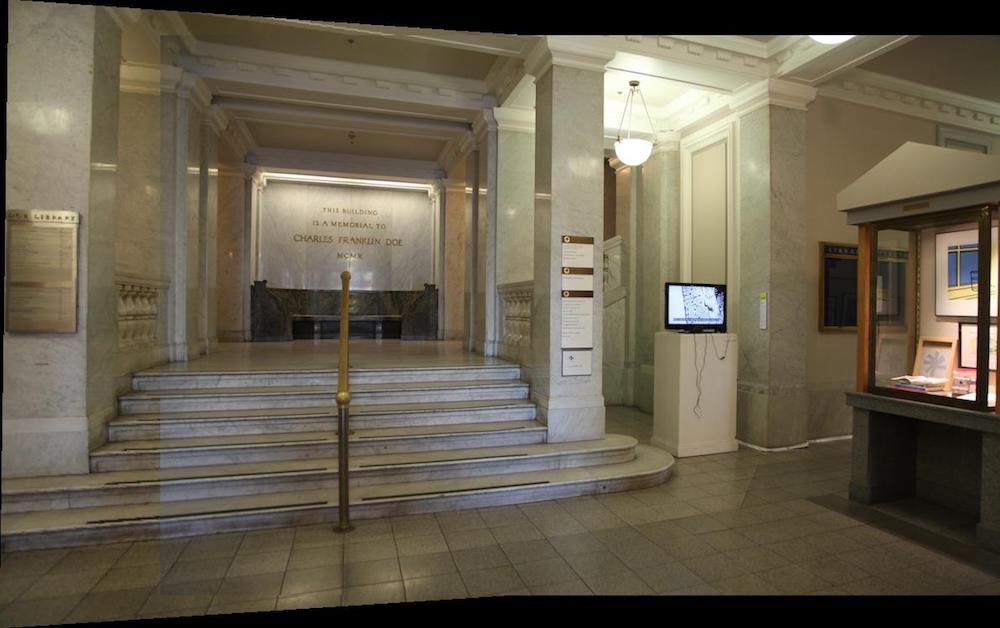
PartA 1.1: Shooting the Picture
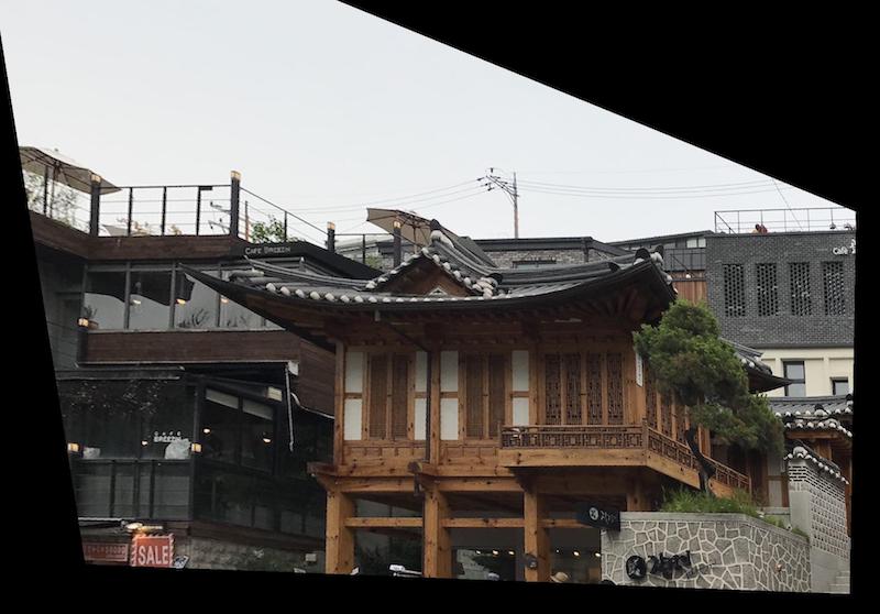
Four photos were taken using a tripod and a camera. I had to make sure that the camera only moved in rotation and the camera was stationary. It was important that the camera didn't move in translational motion for a successful panorama.

From left to right, the images will be called img1, img2, img3, and img4.
PartA 1.2: Recover Homographies
In this part, the corresponding points were picked from the images and the homography matrix was calculated using least squares.
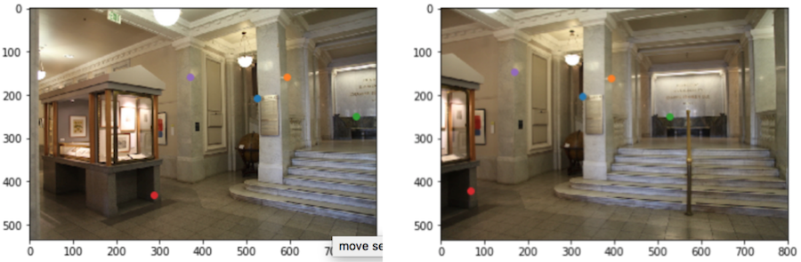
For example, in order to warp img1 from above to the img2, the following corresponding points were picked:
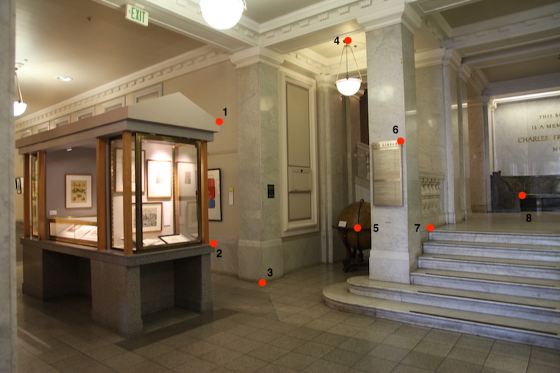
The corresponding points were picked from img2 in the same order.
Next, the homography matrix was calculated using the points. I picked 8 points in order to make the system overdetermined. The matrix equation below was used to calculate the matrix A of the least squares. The left most matrix is A, the second vector is x (which consists of the elements of the homography matrix), and the right most vector is b. from Ax = b, we can perform least squares to calculate x.
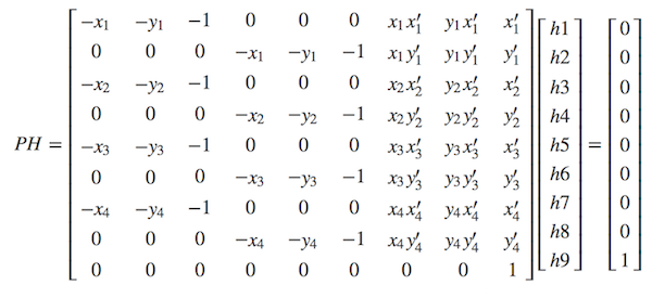
(source: https://math.stackexchange.com/questions/494238/how-to-compute-homography-matrix-h-from-corresponding-points-2d-2d-planar-homog/1289595#1289595)
After the homography matrix is calculated, the new warped points can be calculated by multiplying H with the points: Hp = p'.
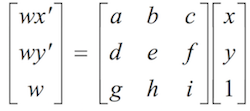
(source: https://inst.eecs.berkeley.edu/~cs194-26/fa18/Lectures/mosaic.pdf)
Notice that a, b, ..., i are h1, h2, ... h9 from the above matrix.
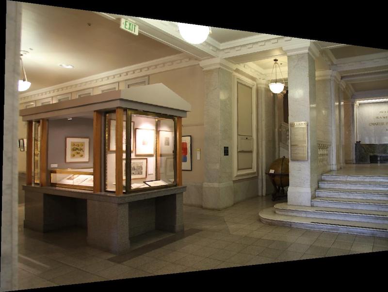
PartA 1.3: Warping the Image
Next, the image is warped using the homography matrix. If the image is warped using the homography matrix calculated about, the following will occur:
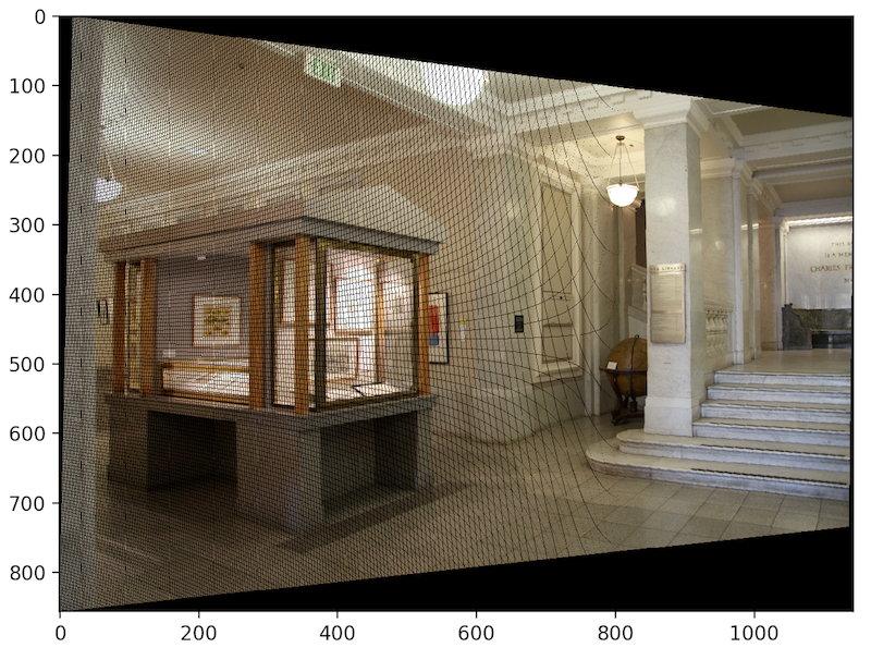
This happens because not all the pixel values will be filled on the new warped image. Therefore, an inverse homography should be done so that every single pixel in the warped image is filled.
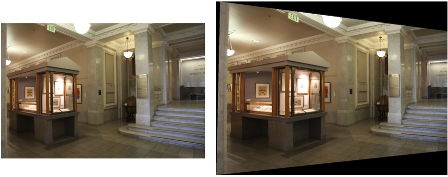
Putting the original picture next to the warped image, you can see the difference between the two.
PartA 1.4: Image Rectification
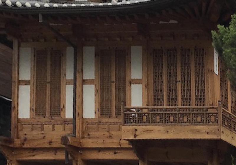
In this part, the image is rectified so that the photo will look like it was taken from a different angle.
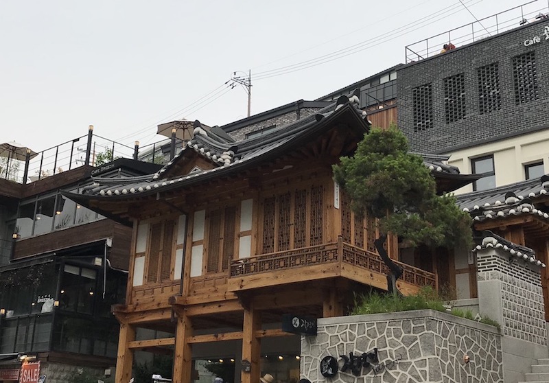
In order to rectify the image from above, I picked four points of the windows.
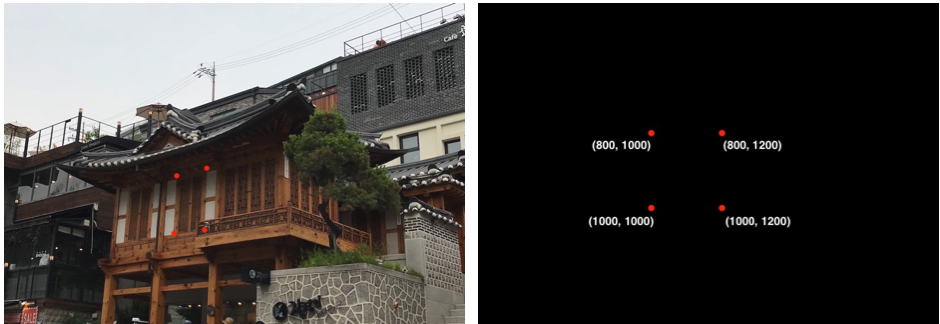
Then I mapped these four points to a rectangle with the corners at (800, 1000), (800, 1200), (1000, 1000), and (1000, 1200).
The rectified image looks like the following:
A cropped image looks better because if you notice the roof of the building, it looks weird.
Another example of the rectified image is shown at the bottom:
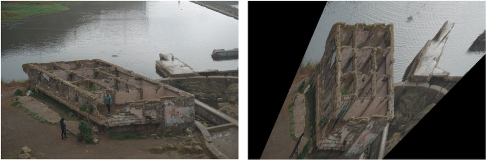
The bath house rectified image doesn't look super good because the angle that the photo was taken and the angle that I am trying to reconstruct is TOO different. I think the image above was much more successful.
PartA 1.5: Blending the Images into a Mosaic
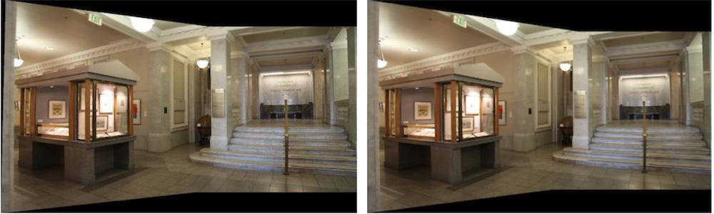
In this part, I blended the warped image with the other image.
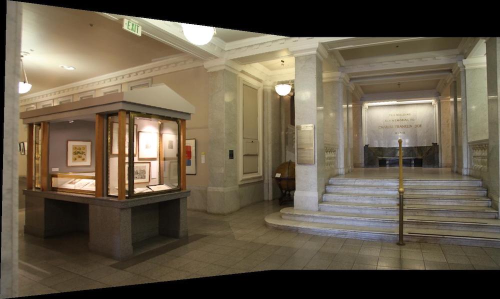
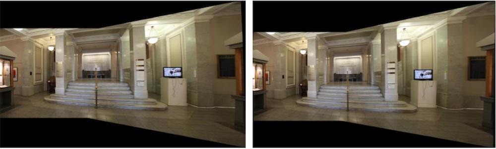
To create a full panorama, Mosaic 1 and Mosaic 2 can be stitched together.
These images are created by using stitching and blending. As you can see from the bottom, without blending the image looks like the following:
You can see from the left side of the image that there is a very clear distinction from im3 and im4. Therefore, obtaining the maximum pixel value at the point and a weight (for example 0.9) is used to blend the two pixels together. The result is successful as you can see from Mosaic 3.
PartA: What I've learned
In this project, I learned how to warp and rectify images. Warping and rectifying images uses the same concept and have similar procedure, but their purpose is different. By warping images, I was able to construct a panorama of multiple photos. By rectifying the picture, I was able to compute a photo from a different lightfield than the lightfield.
Overall, it was a cool project to understand direction of lightfields and how panorama works from my phone camera.
PartB Step1: Harris Interest Point Detector
In PartB, the points that are manually picked from PartA will now be picked automatically from the program. To begin this automated process, the program should pick the right points on each image that corresponds to each other.
The code from harris.py given from the instructor is used to compute the points that are corners.
Above, the two images im1 and im2 are shown with the result of harris_corners function. I set the minimum distance between the points to be 20 for this case, since with min_distance smaller, there were way too many points.
PartB Step2: Adaptive Non-Maximal Suppression
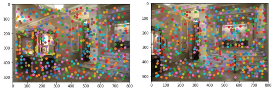
For ANMS, the goal is to pick the points that have high corner strength. This is done by ordering the above points from above (around 580 points) and choosing N number of corners with the highest coner strength.
In the above im1 and im2, n = 500 was used. You can see that there are some corners that are matching between the two images, but there are also points that don't correspond to each other and in general, 500 are too many. Which is why next is making sure we are only left with the corners that correspond to each other.
PartB Step3: Implement Feature Descriptor and Feature Matching
This part is finding which points correspond to each other from the two images. First, 40x40 pixels are chosen around each corner and the descriptor is rescaled to 1/5 to be a 8x8 pixel image. Then each of the 500 descriptors are compared between the two images to find the best corresponding corners between the two images.
While doing the comparison, it is important to determine if the it is indeed the right corresponding corners. The way to do this is to compare the 1st nearest neighbor (1-NN) with the 2nd nearest neighbor (2-NN). By looking at the ratio of 1-NN/2-NN < threshold, we can know that the corner is indeed the right corresponding corner. In my code, I used threshold = 0.5 or 0.6.
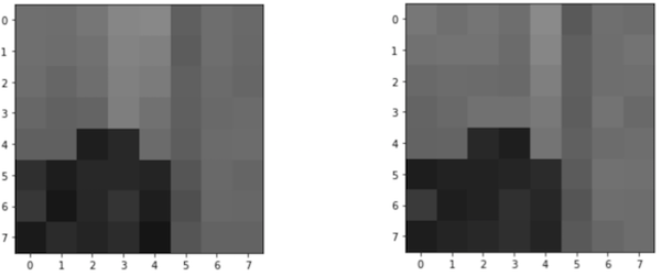
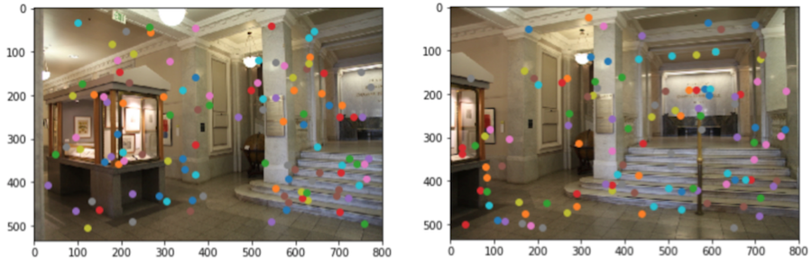
Above is an example of one of the descriptors from im1 and im2 that match. After comparing the descriptors from the two images, below are the points (around 30) that are determined to match.
The points with the same colors are suppose to be the one that correspond to each other.
PartB Step4: 4-point RANSAC
This is the final part from PartB which is wehre you run Random Sample Concensus code to further determine which are the right corresponding points, since clearly from the above image, you can see that not all the points match.
RANSAC is done by randomly picking four points from the set of points and comuting a homography matrix. Afterwards, the points from im1 is warped to im2, and the warped im1 points is compared to the im2 points. If the distance between the two points are less then the error value (e = 0.2 from my code), then that means that the point is an inlier.
This loop was ran 500 times, and the homography matrix with the greatest number of inlier is chosen to be the correct homography matrix.
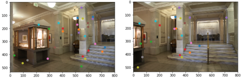
Above is the result of RANSAC. You can see that the five points that are returned are correctly corresponding and now warp can be done using the warping code written in PartA.
PartB and PartA Comparison
Now the result of PartA and PartB can be compared. The left image will be the image from PartA and the right will be form PartB
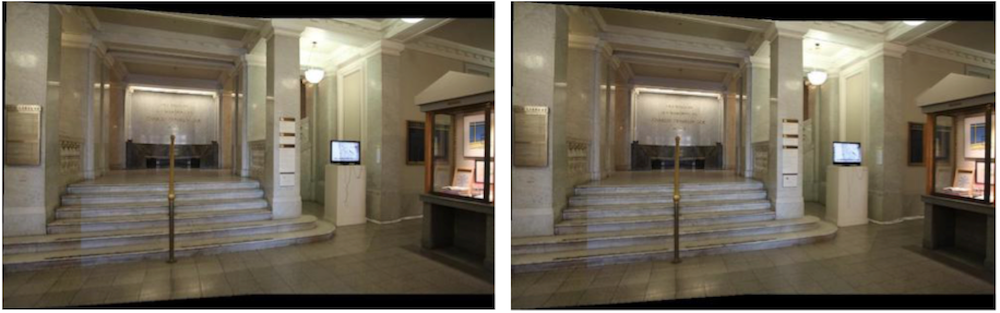
As you can see from above, the image from both parts are almost the same. This shows that PartB was done succesfully and I wouldn't have to pick points manually to perform warping.
PartB: What I've learned
From PartB, I learned how to pick points automatically using Harris Corners, ANMS, MOPS, and RANSAC. It was an interesting experience because the code worked better than I thought (especially the RANSAC) and once I finished the coding for one set of images, all I had to do to warp new images was to run the entire code again (although I had to fix sum bugs). It was a cool experience to automate something that I have manually done on the previous part!
Last Edit: 11/24/2018