Image Warping and Mosaicing
CS 194-26: Project 6b
Caroline Moore (cs194-26-aew)
For this project, we warped and aligned images so they could be blended to create mosaics. There are several steps to this process.
Find Corners using a Harris Detector
A Harris Detector finds corners in an image by identifying small regions of the image with significant change in all directions. For example, our Harris Detector found the edges marked with red dots in the following images.

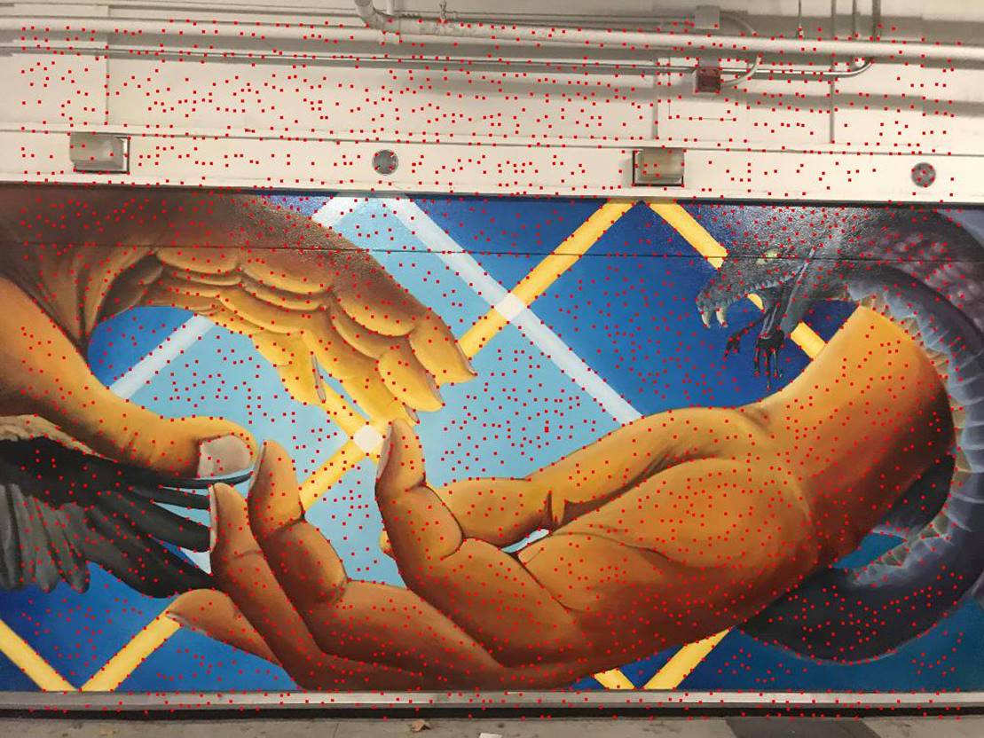
Top left: Detected corners on left side of the mural. Top right: Detected corners on middle of the mural.
However, we don’t want all of these corners, so we reduce it
to only the 250 strongest. However, we want these 250 points to be spread out,
so we use radius suppression. We find the radius ![]() for each corner using the equation below and
keep the 250 points with the largest radius.
for each corner using the equation below and
keep the 250 points with the largest radius.
![]()
The resulting corners are marked on the images
below.
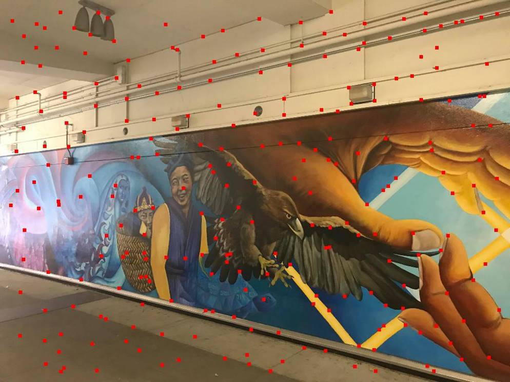
Top left: Detected corners on left side of the mural after radius suppression. Top right: Detected corners on middle of the mural after radius suppression.
Match Features
The next step is to match the corners in each image. To do this, we first need to extract a descriptor for each corner, which is the 40x40 square around the point smoothed and subsampled to be 8x8. This makes the corners in both images appear similar even if they are slightly warped. We can then find the “distance” between every pair of corners. For each image, we identify its nearest neighbor and its second nearest neighbor, and if the ratio of those two is below some threshold, I used 0.4, then we say those points have matched. However, there will be some false positive matches.
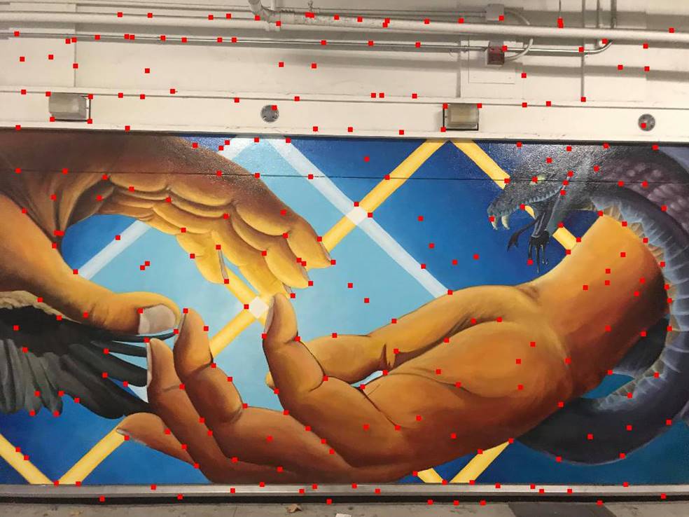
Below are the same images, but with only the corners that matched marked.

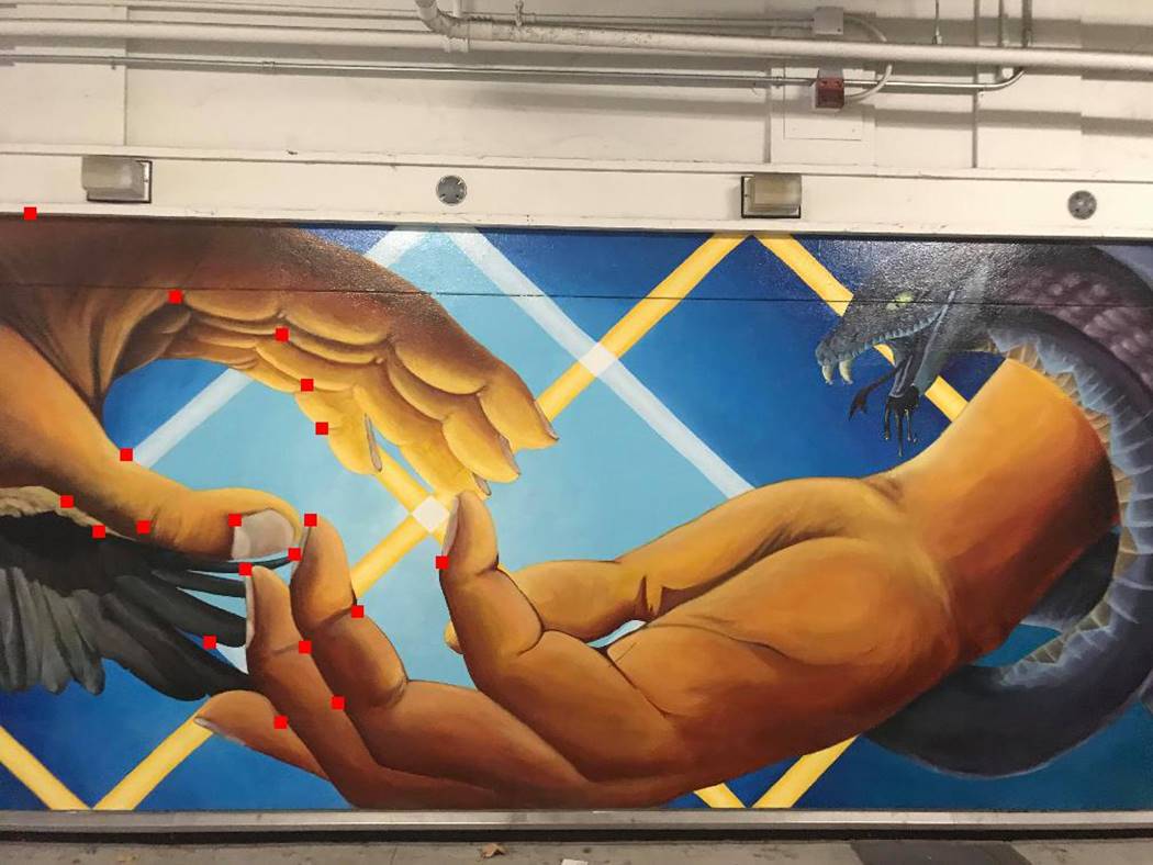
Top left: Detected corners on left side of the mural after matching points. Top right: Detected corners on middle of the mural after matching points.
Find the Homography
It is simpler to find the homography
if we know all pairs of points match, such as if a human labled
the points. In this case, the points in the image that is going to be warped are
![]() and the points that they will be warped to are
and the points that they will be warped to are ![]() .
I can then use these points to find a homography
between the two images. To convert between them. To do this, I first define the
following matrices.
.
I can then use these points to find a homography
between the two images. To convert between them. To do this, I first define the
following matrices.
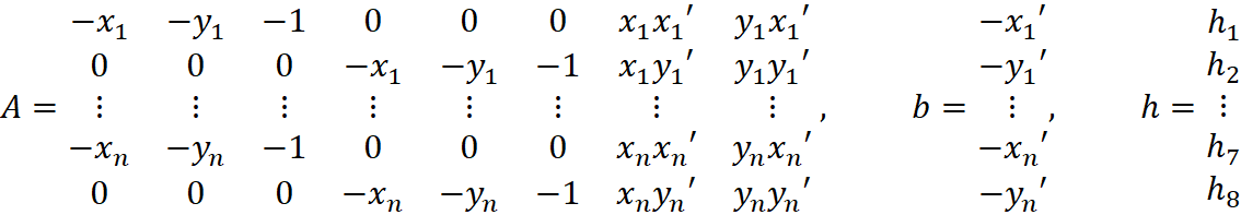
I then used least squares to solve for ![]() using
using ![]() and
and ![]() .
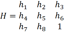
Rewriting
.
Rewriting ![]() gave me the homography
gave me the homography
This lets me warp the first image onto
the second set of points using the following equation.
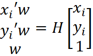
This lets me find where the edges of the
image should be so I can determine the size of the warped image. Then I use the
inverse of the previous equation to find the value of every pixel in the warped
equation.
To test my code, I first warped an image
of a trapezoid into a rectangle.
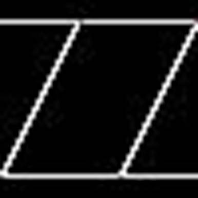
Left: trapezoid. Right: warped rectangle.
Then, I warped a picture of a cube of
magnets so different sides faced forward.
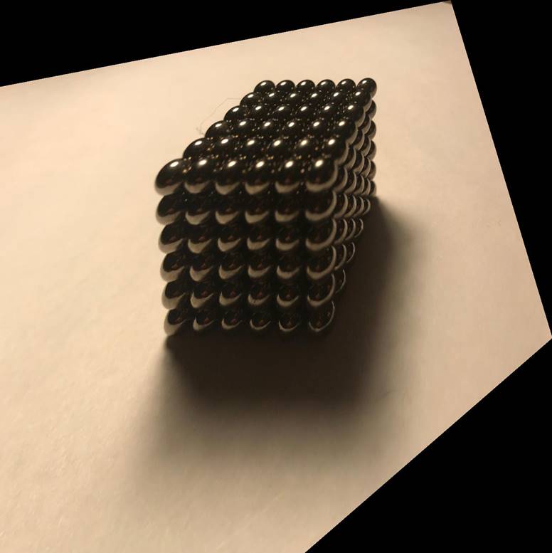
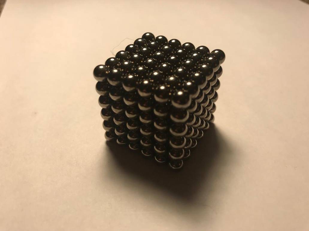
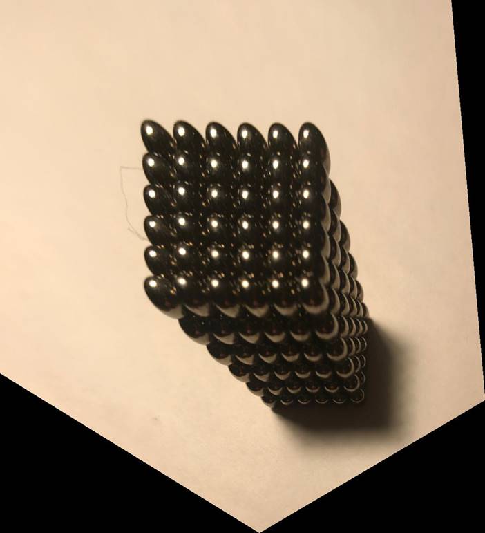
Left: Cube warped so it’s left side faces
forward. Middle: Original picture of the cube. Right: Cue warped so it’s top
faces forwards.
However, when the corners were matched
automatically there will be some false positives so we need to identify a set
of good points to use to make the homography as
above. We assume that there are more correct matches than incorrect matches and
that not all of the incorrect matches line up with each other. To find a group
of “good” matches, we randomly choose 4 pairs of points and find the homography between those points. Then, we apply the homography to each point in the image we will warp and
check if it is within some threshold of the point’s match. If it is, we
consider it an inlier for that homography. We repeat
this process many times and then use only the largest group of inliers to
generate the homgoraphy. The next section has some
examples of mosaics.
Mosaics
Next, I created mosaics by merging images.
I warped one image to align with the other image and then used feathering to
blend the images.


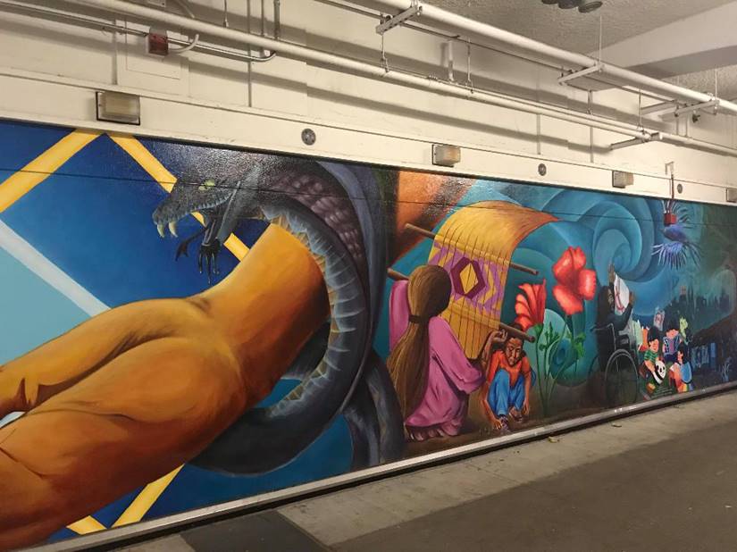
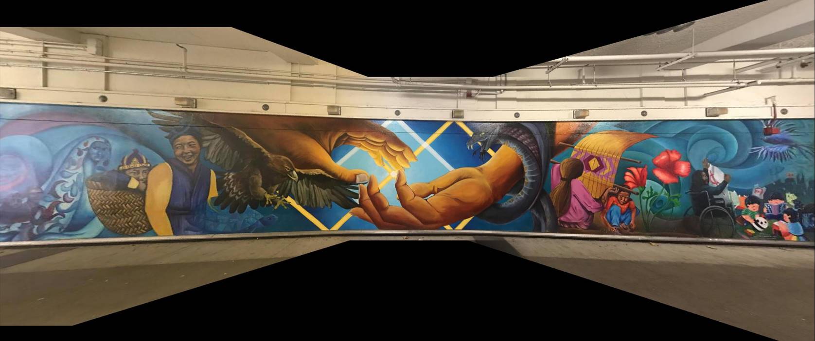
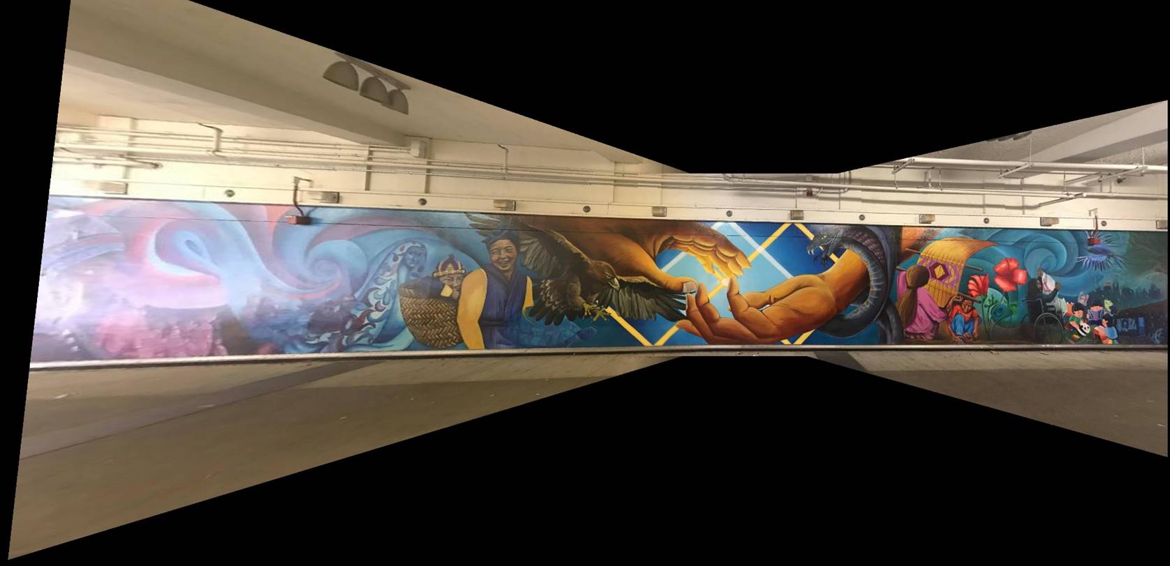
Top left: Left side of the mural. Top middle: Middle
of the mural. Top Right: Right side of mural. Middle: Blended mosaic using
human labeled points. Bottom: Blended mosaic using automatic feature detection.
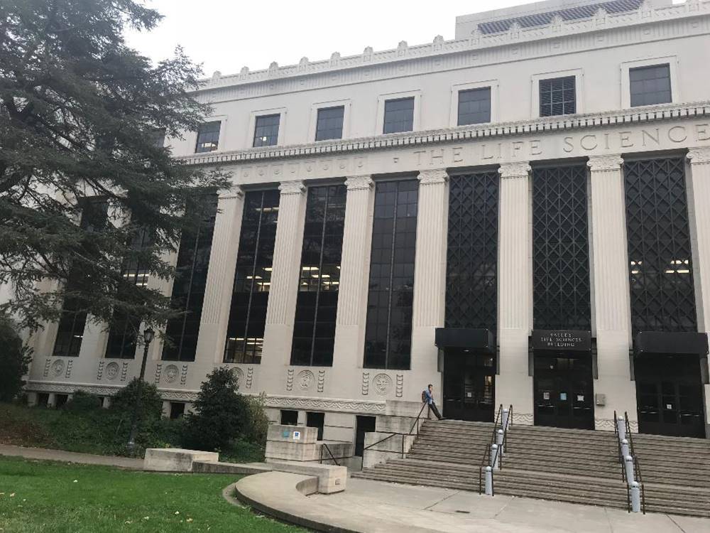
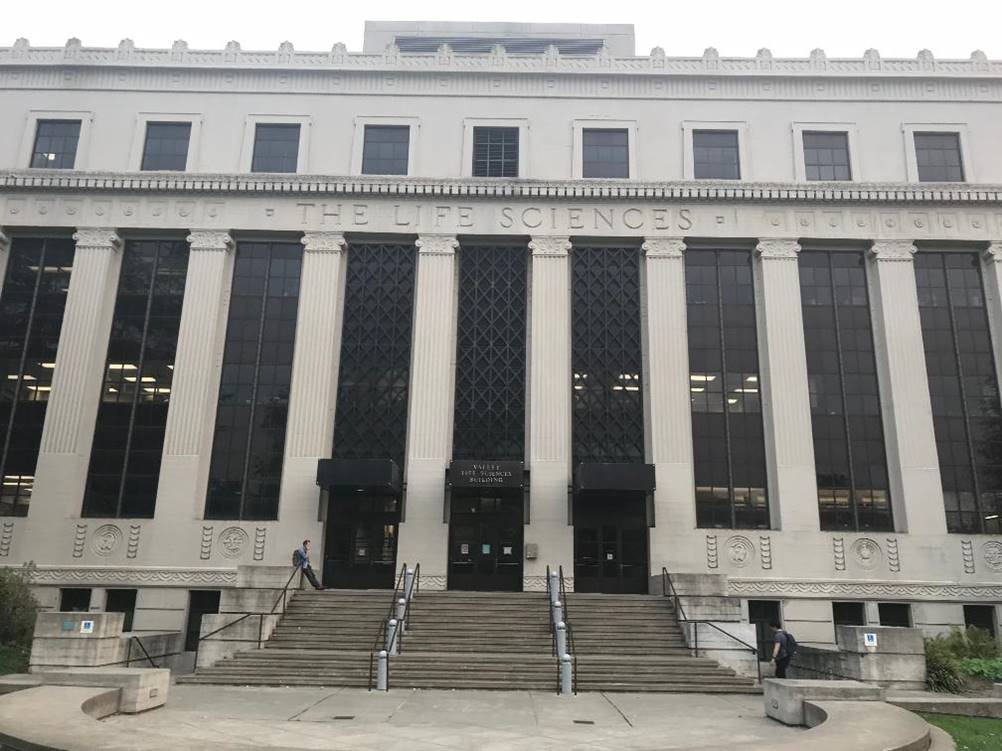
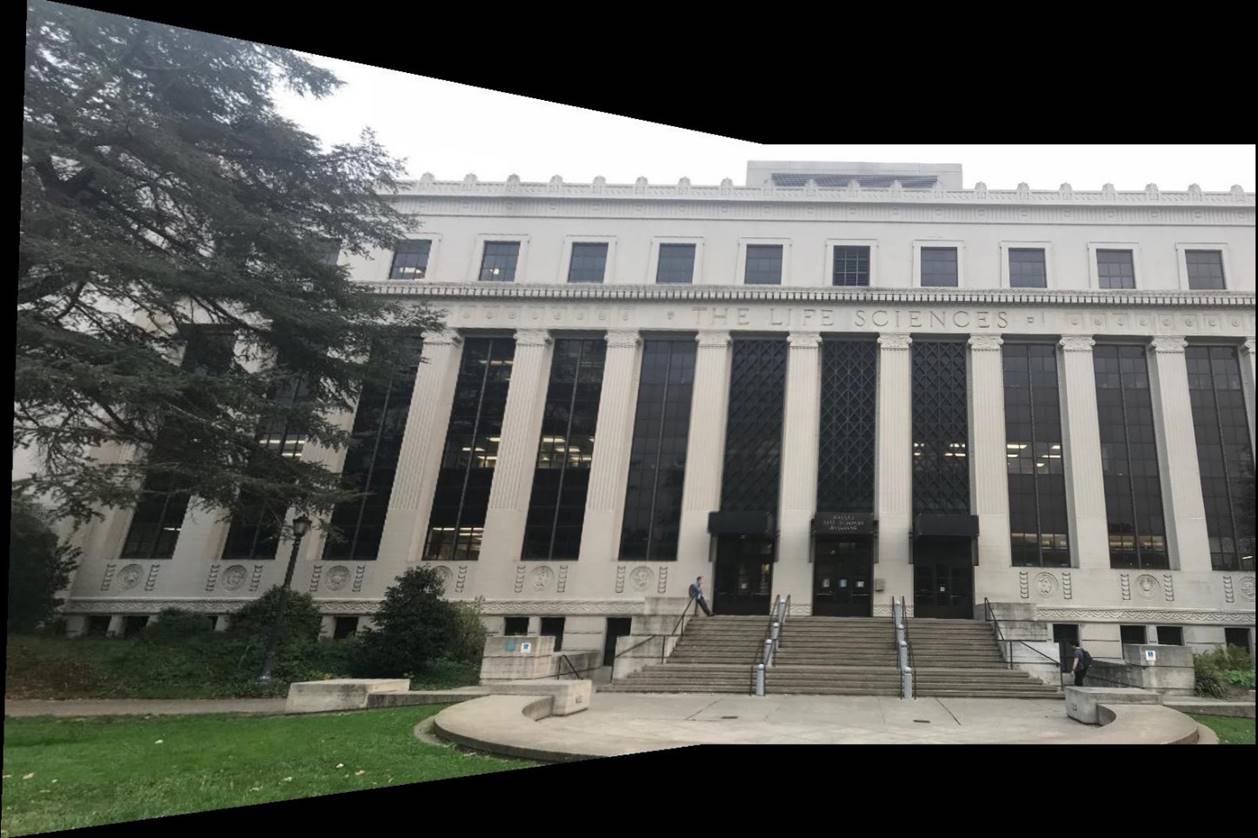
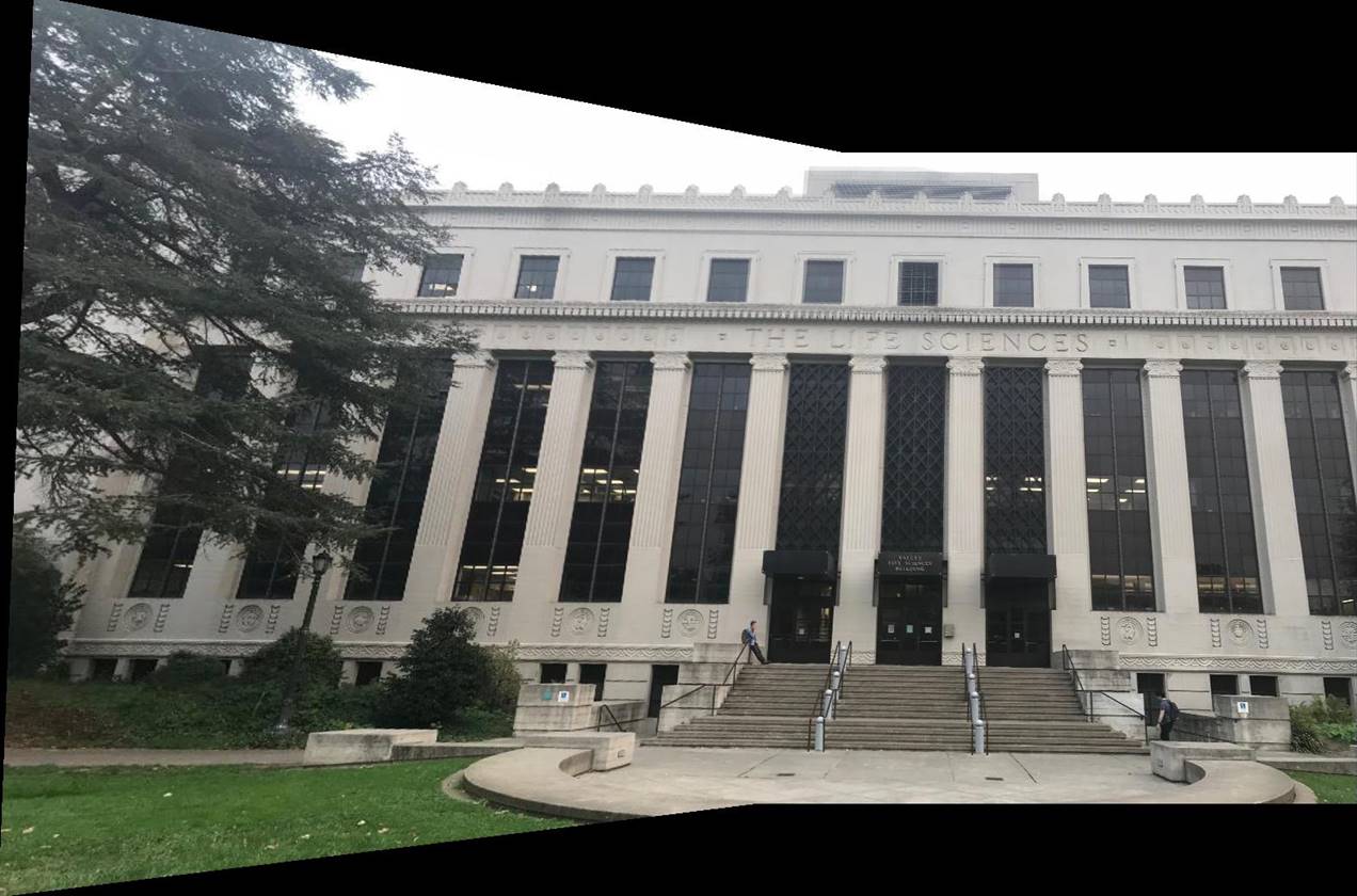
Top left: Left side of VLSB. Top right: Right
side of VLSB. Bottom right: Blended mosaic using human labeled points. Bottom
left: Blended mosaic using automatic feature detection.
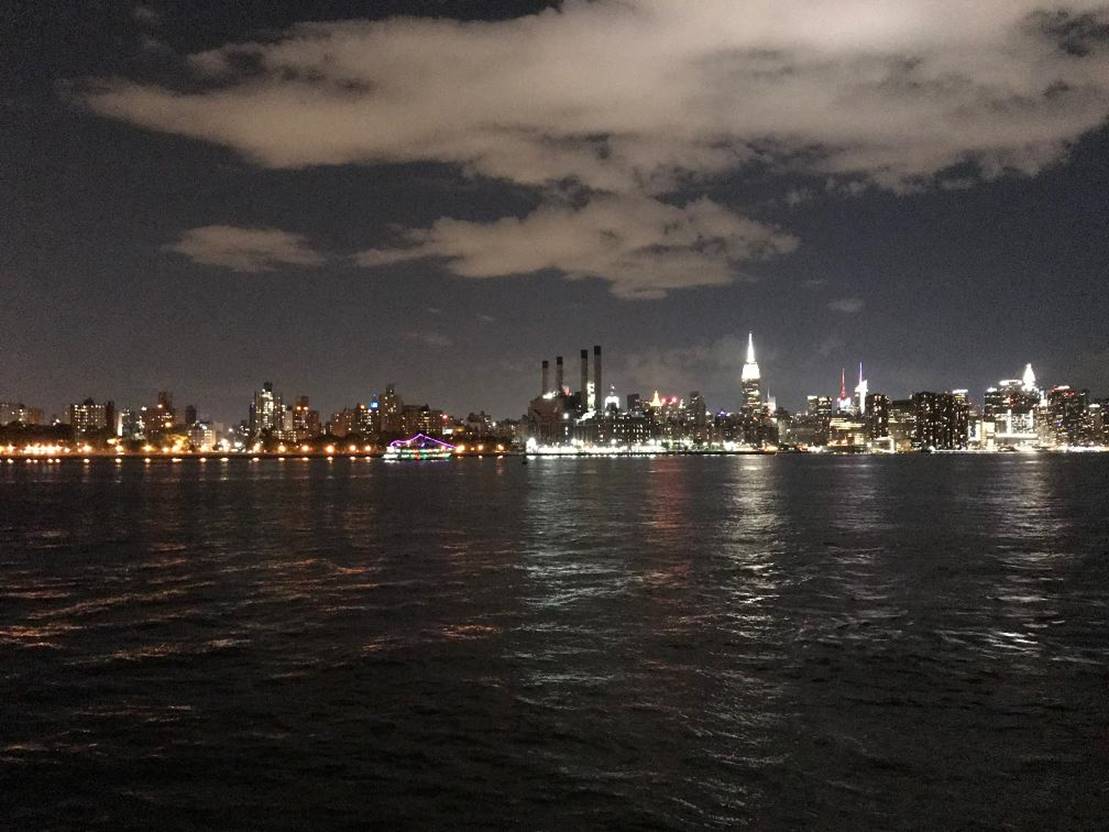
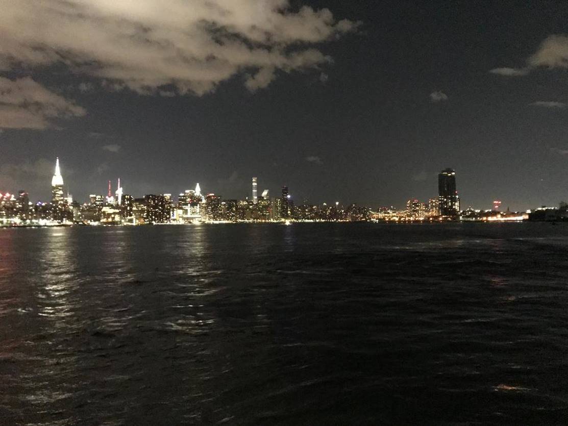
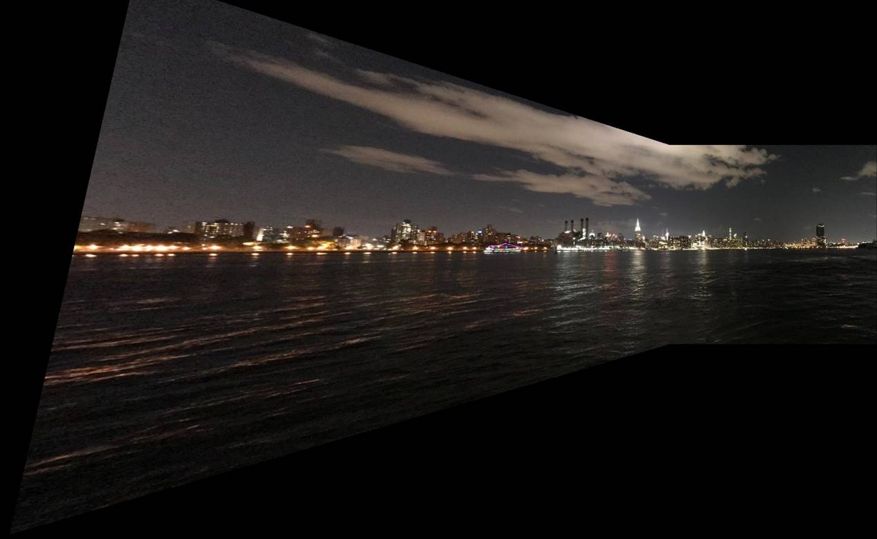
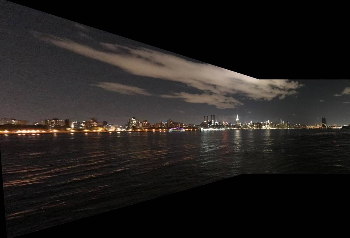
Top left: Left side of the skyline. Top right:
Right side of the skyline. Bottom right: Blended mosaic using human labeled
points. Bottom left: Blended mosaic using automatic feature detection