Shooting the Pictures
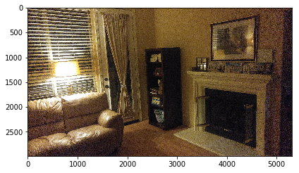
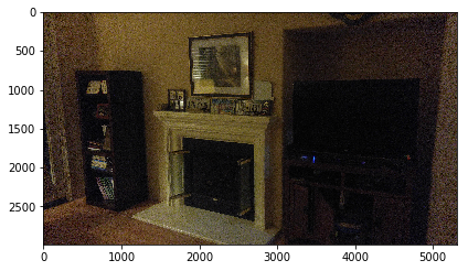
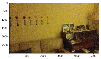
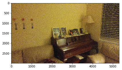
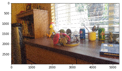
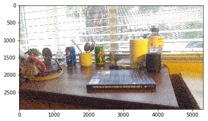
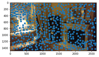
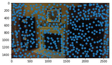
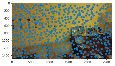
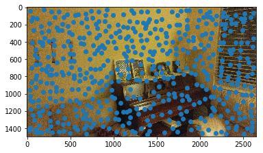
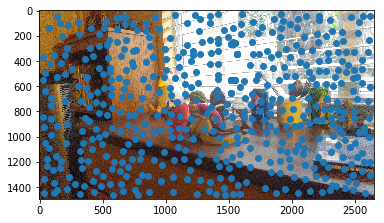
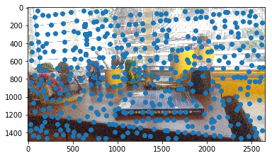
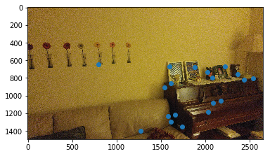
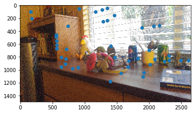
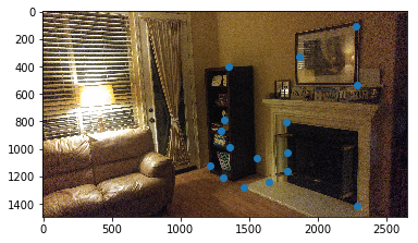
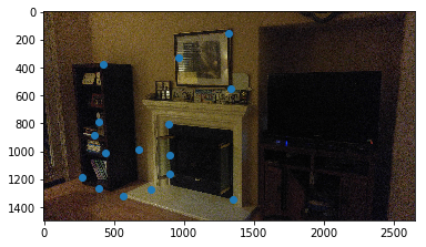
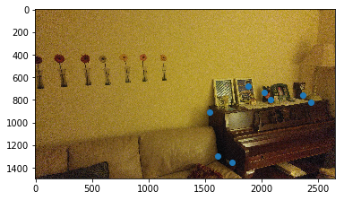
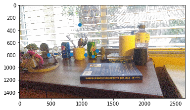
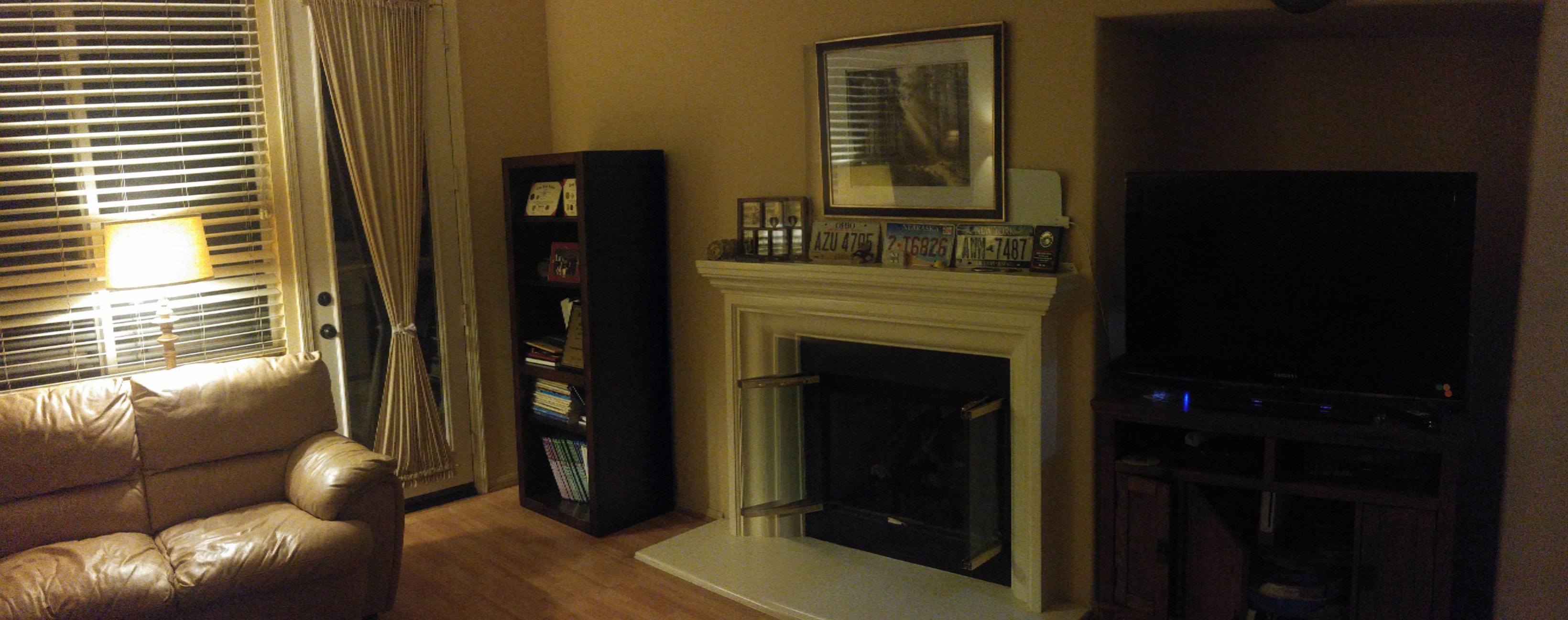
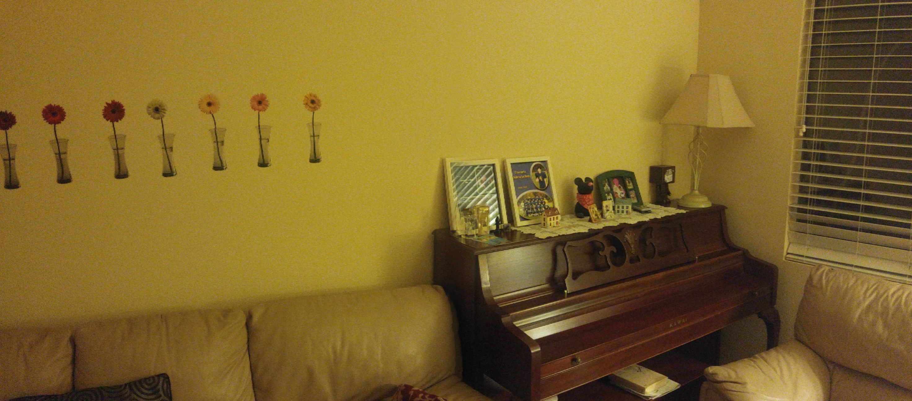
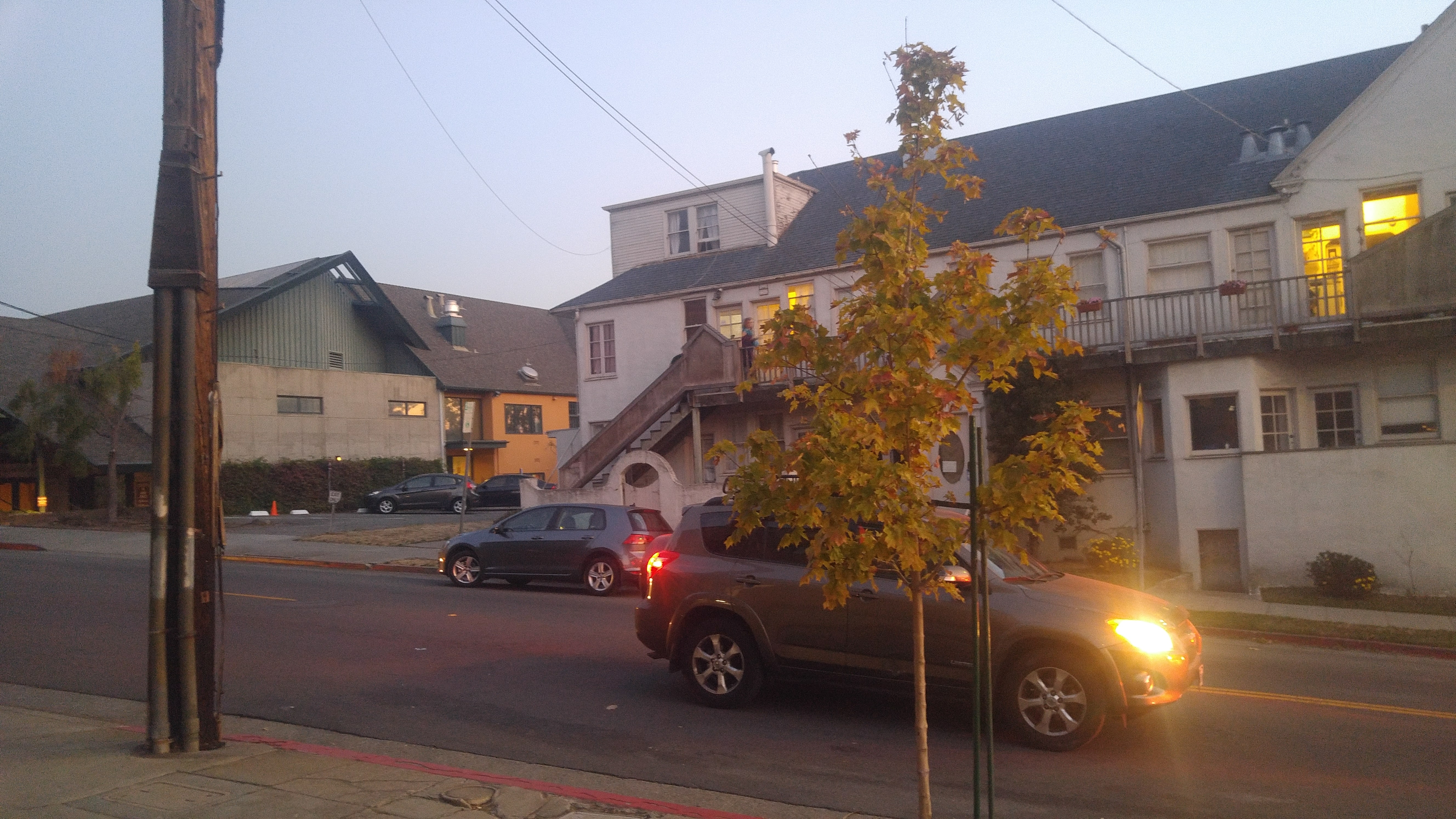
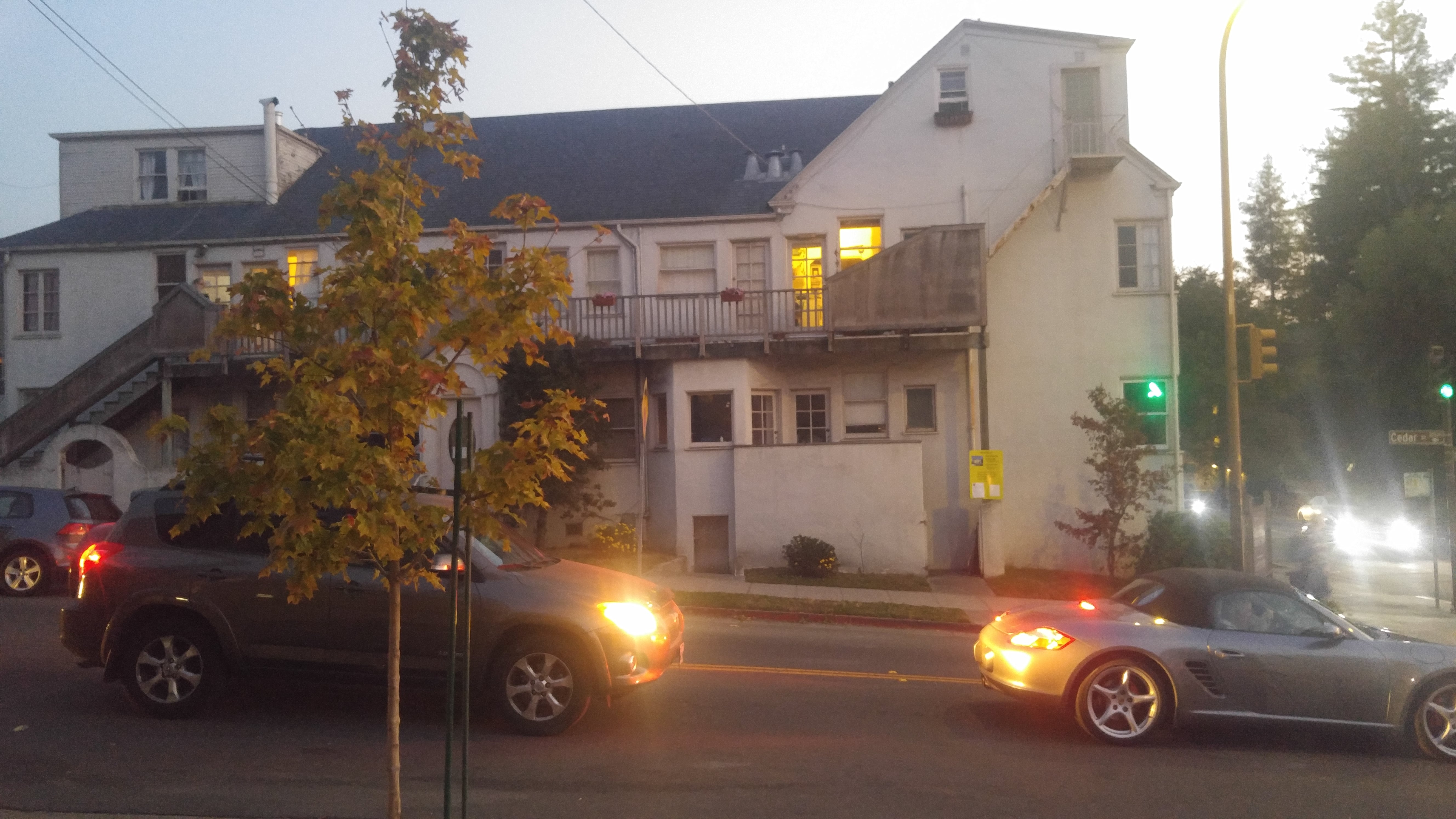
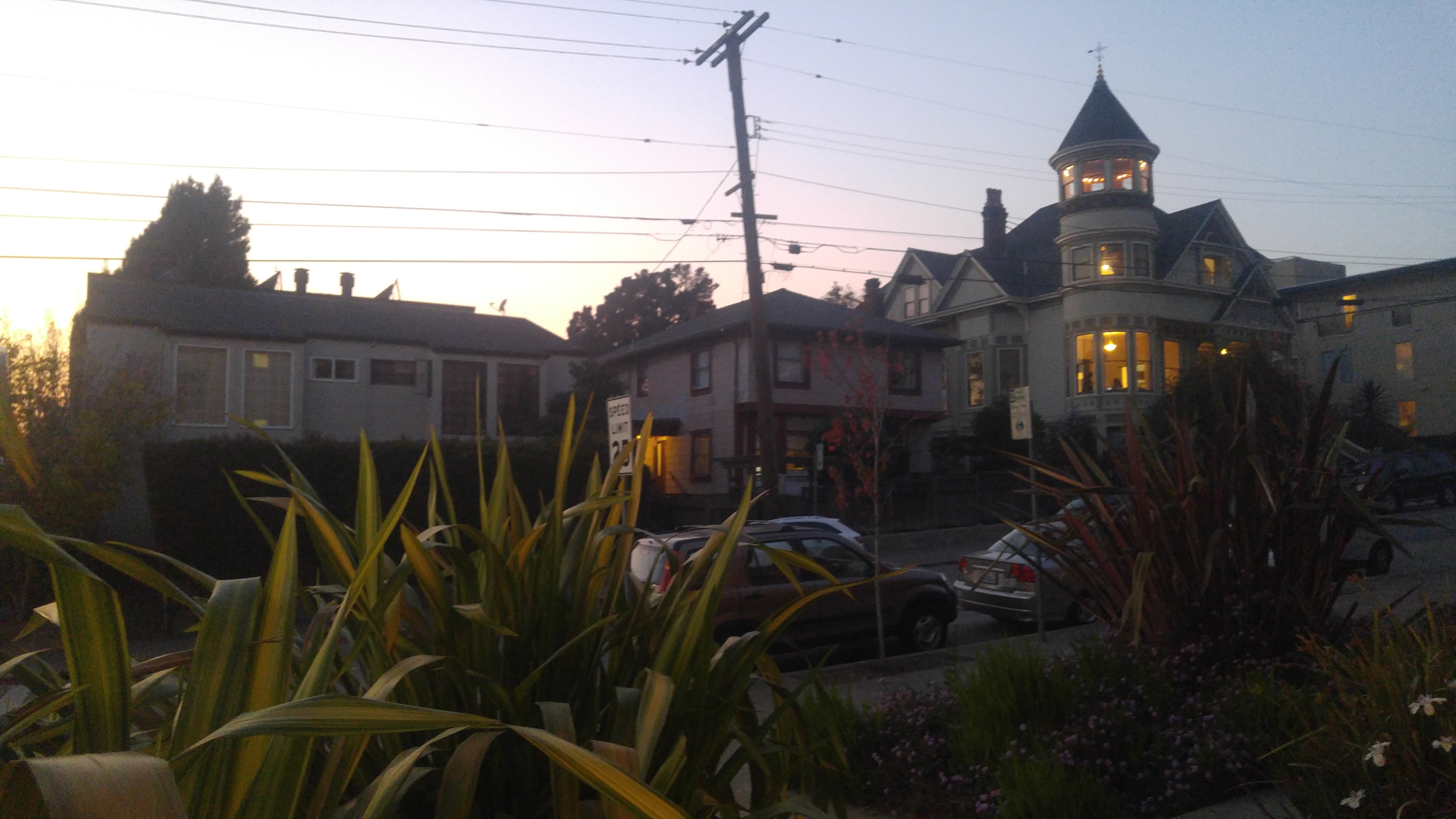
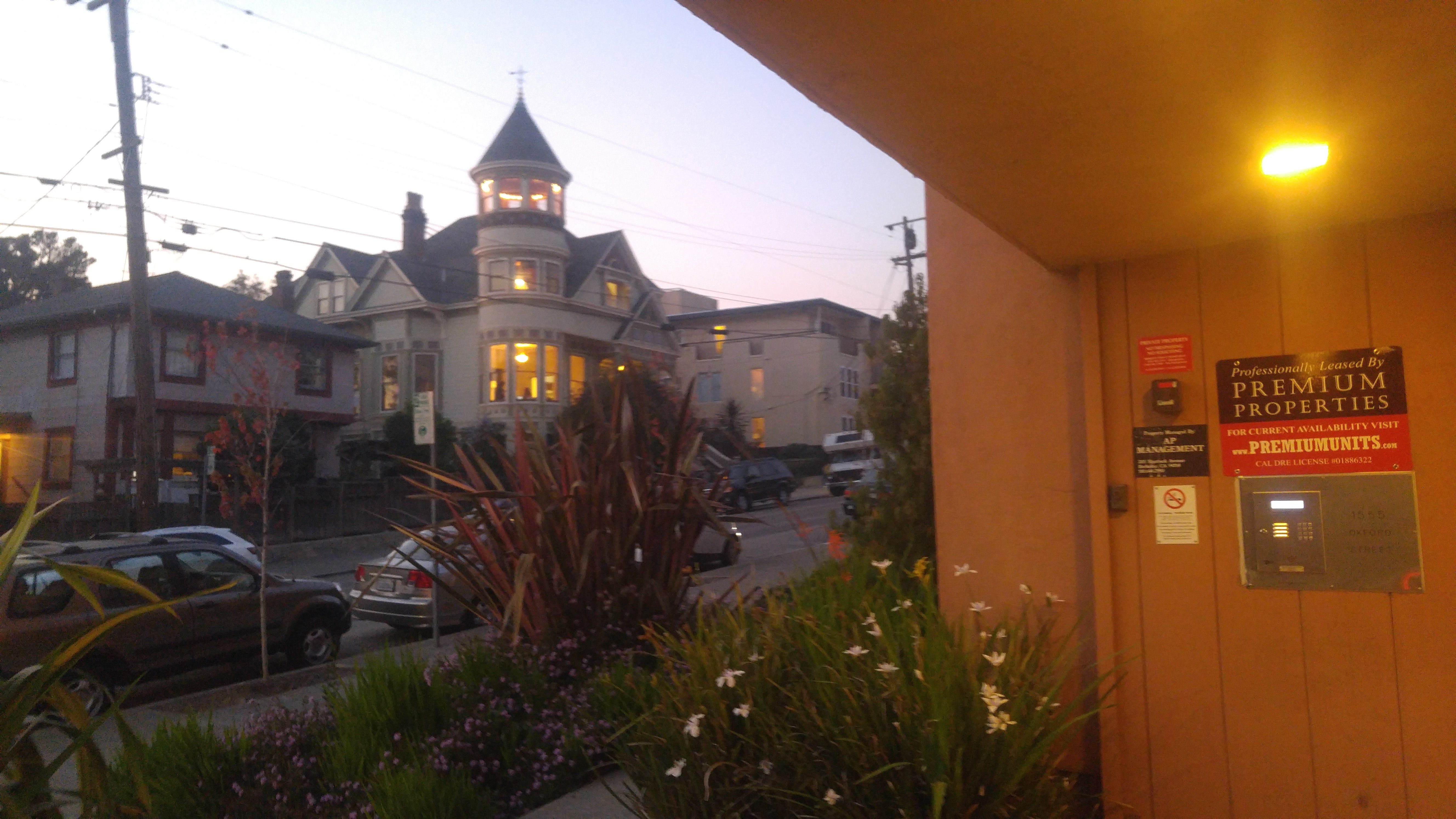
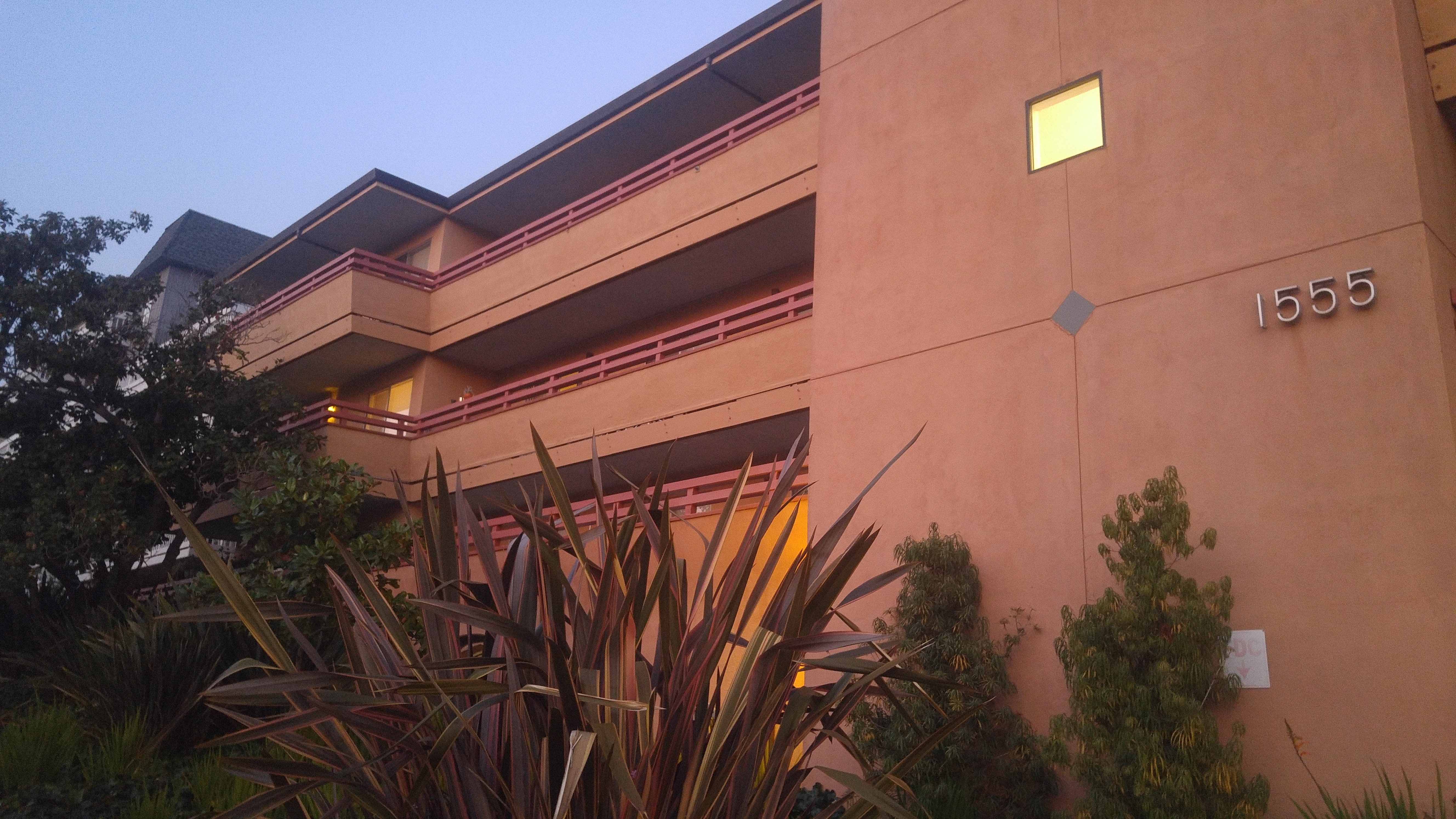
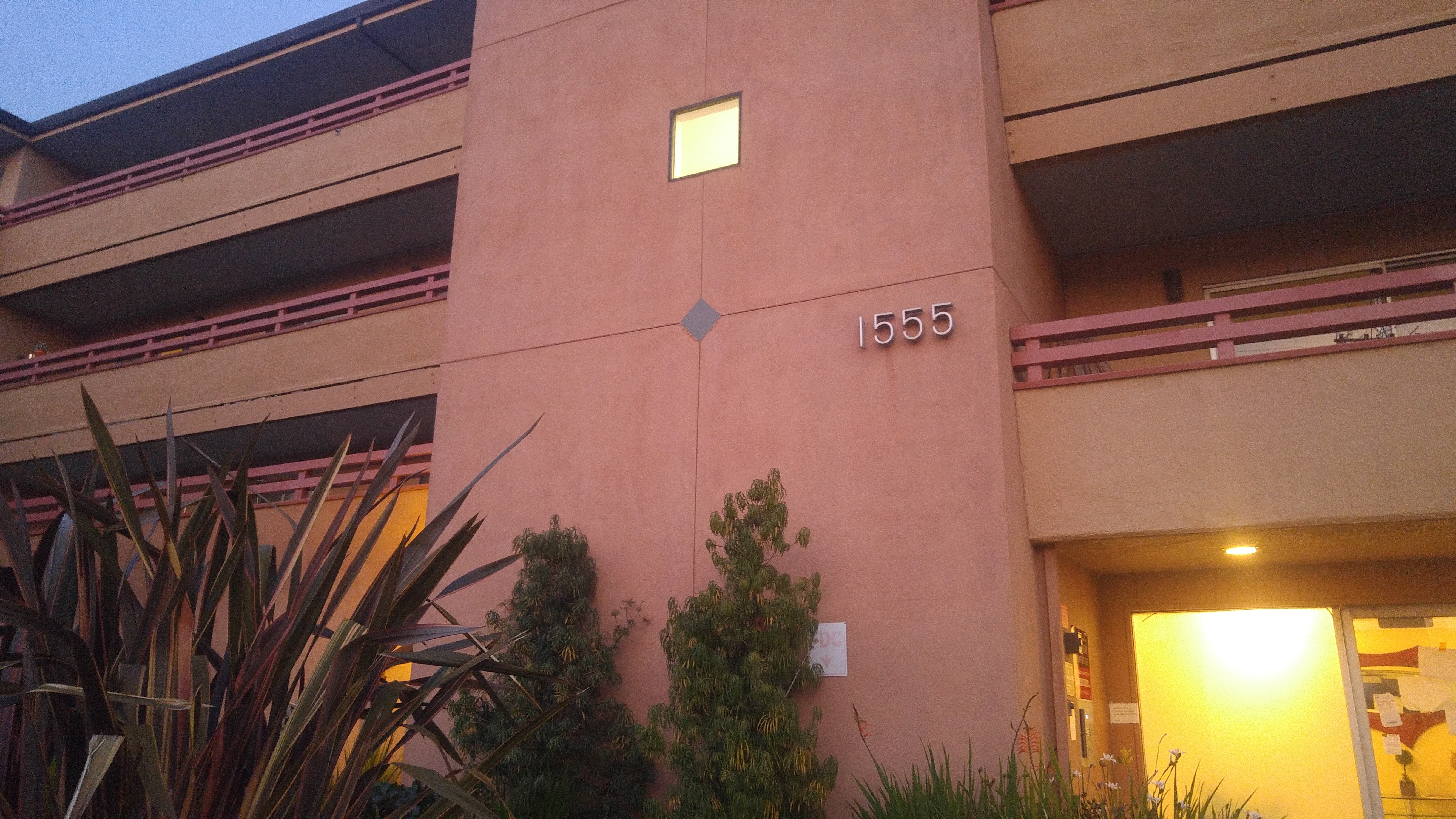
Below are some photographs I took that are from the same point of view with overlapping fields of view, but differnt view directions, thus ensuring that the transforms between the two images were projective. I took pictures with the same camera settings between the same images to ensure the images could be stitched properly. The pictures I took were street view pictures from the front of my apartment, as well the front of my apartment.
Recover Homographies
Recovering the homography matrix is similar to finding the affine transformation matrix but there is one more degree of freedom (8 total). As a result, I used a procedure similar to the equation listed beow where (X, Y) represent points in the original image while (X', Y') represent points in the new point. I also included a last row to the matrix of [0, 0, 0, 0, 0, 0, 0, 0, 1] and included a one at the very bottom of the column vector on the right side of the equation.
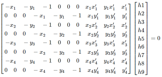
Using the procedure shown above, but using multiple points rather than just the one shown in the image above, I am able to retrieve the 3x3 matrix. Finally, to use the homography matrix, one should right multiply the homography matrix with a column vector consisting of (X, Y, 1). The product will be of form (W * X', W * Y', W) which you can just divide out the W factor to retrieve the transformed points.
Warp the images
To warp the images, I simply computed the homography matrix between the two images by selecting points of correspondences on both the images that correspond to the same object or the same shape of the object I'm attempting to warp into. Afterwards, I just iterated over all the pixels in the new image and then found the corresponding pixel in the original image using the homography matrix, and then copied over the original image's pixel value over to the new image.
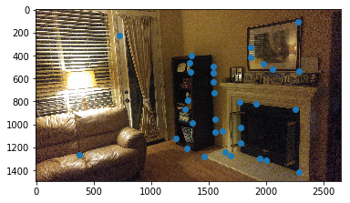
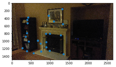
Rectified Image
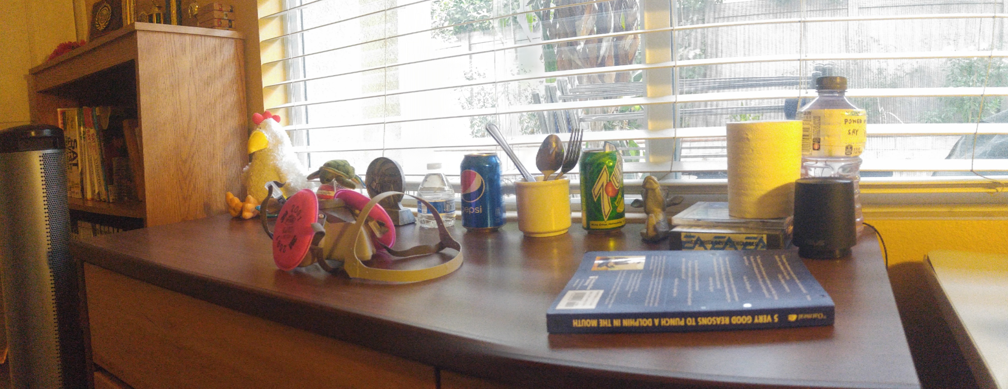
Below are some examples of rectified images that I created using the methods I spoke above. I chose the correspondence points to be 4 points on my original image to be the four corners of a square within my original image but isn't an actual square in the image, and the other 4 points to be [(0, 0), (1, 0), (0, 1), (1, 1)] which represent a square. I then found the homography matrix and then warped the image. Unfortunately, I didn't have enough time to sort out the finer details that come with coding rectifying an image.
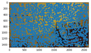
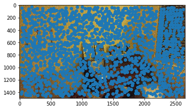
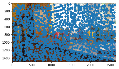
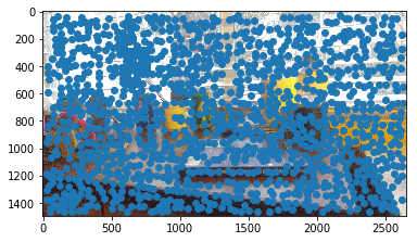
Blend the images into a mosaic
Creating a mosaic is very similar to rectified images, except you rectify the images to each other rather than an imaginary square. I chose correspondence points that correspond to the same objects within each of the images (but that obviously have differnt points because they're from different perspectives). After rectifying several images to a single base image, you would just do a simple average blending to stitch the images together to create a mosaic.
Tell us what you've learned
I learned again the power of data! Through having taken pictures from the same point of view with overlapping fields of view but different view directions, I was able to create interesting images such as mosaics and rectified images. I also learned that there is a lot of power in having a sort of point of reference (points of correspondence in our case) to use to manipulate images.