Following the paper by Efros and Freeman, the goal of this project is to generate texture images that give the same appearance as a source texture by randomly sampling the source and combining it in patches. The end result is an algorithm that can generate arbitrarily large versions of the same texture and map that texture onto existing images.
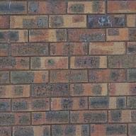
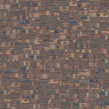
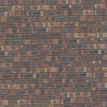
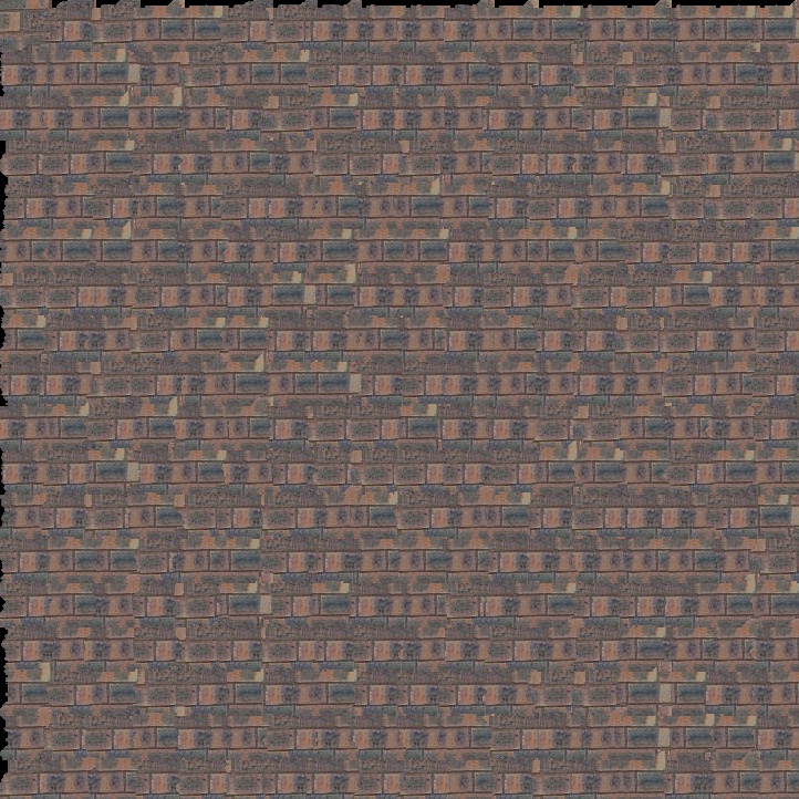
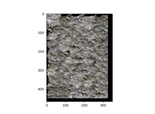
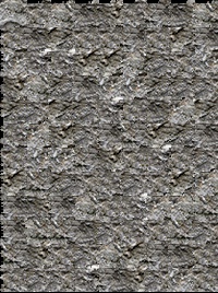
A first naive approach that we were instructed to try was simply pasting our randomly sampled patches side by side to tile the output image. This captures some of the texture's apearance if the patch size is large enough to capture its structure, however it leaves very noticable lines at the borders of the patches. Below is a brick texture that has been quilted to twice its original size with this technique.
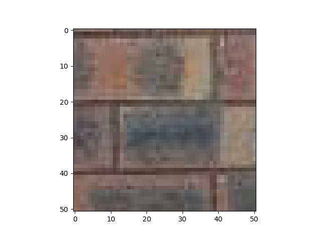
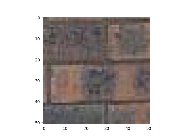
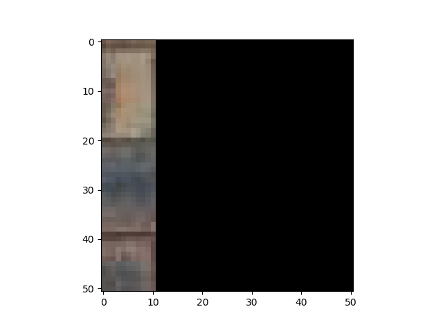
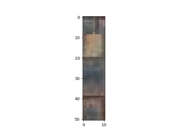
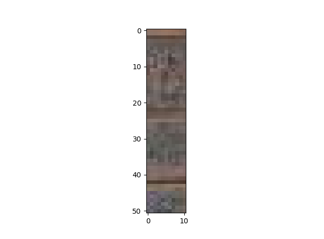
A quick improvement to the algorithm is by laying down patches with a little overlap and at each step choosing the patch that matches the best with what we already have in the overlap region. Here are some example patches from the bricks texture and an example overlap region.
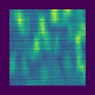
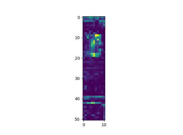
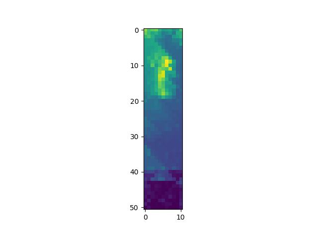
The best match of our set of possible patches is the one with the minimum sum of squares distance. In order to add some variation to the end texture, I chose a patch from the best k matches at random. Below is an image where each pixel is the cost of using the patch centered at that pixel in the source image as well as the result of using this technique to tile the output.
While there is a lot of improvement, but some of the edges between patches are still visible.
The next improvement upon this method is that after matching good patches to the target location, we compute a minimum cost cut between what is already there in the overlap region, and what we are adding. This allows us to cut up the border of the patch being added so that it better meshes with the existing texture. Below is an example of the cut done on two overlap regions
Given the SSD error, I found the minimum cost cut using dynamic programing. The minimum possible cost of a path to reach the bottom of the overlap, call this E, starting a given pixel (i,j), given the ssd error e is given by e(i,j) + min( E(i-1,j), E(i+1,j), E(i+1,j+1)) or the ssd error of that pixel and the minimum possible cost of path from the pixels directly underneath it. An example of this computation filled out is given below as cumulative error. Notice how the error at the bottom of the overlap region is low and increases the higher up you go. After finding the cumulative error, the minimum cost cut is taken by grabing the cheapest pixel in the top row, and then for each following row, the cheapest pixel reachable from the last chosen pixel.
Here is an example of the cut applied to a patch. The overal cut is found for the left overlap region, the top overlap region by transposing and finally taking the intersection of these two cuts.
Below is a comparison of the output with both added improvements against the first randomly placed patches approach.
Below are two more examples of the min cut and sdd error fitting combo
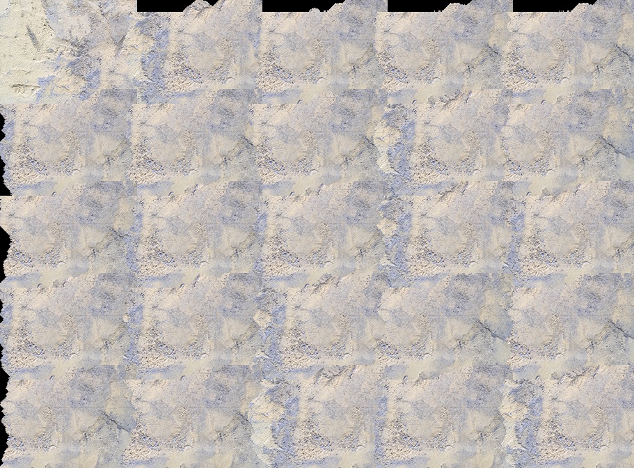
Here are a few examples using other textures
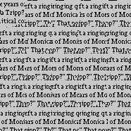
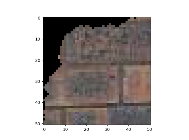
Now that we have a texture synthesiser, we can add in an error term for a target image in order to map texture to look like that target image. The error term is found by looking up the corresponding patch in the target image, and then createing a cost image similar to the one used in the SSD error. For each pixel location in the sample image, we find the SSD difference between the luminace of the patch centered at that location and the luminace of the patch in the target image.
Here is me trying to tile a rock texture onto a face. In the first I used an alpha of 0.5 and a patchsize of 1/10th the image height. This didn't prioritize the target image enough and didn't have enough patches for variation. The second used an alpha of 0.2 on the same face but the output image size wasn't large enough. In the next I used alpha 0.05 with a larger target but the face still didn't show up.
I made my own cut function which like described above, uses dynamic programing to solve for the cumulative error at each level of the overlap image. I then paste together masks tracking the min cut along the edge and take the intersection of the masks of the top edge and left edge for the final mask to apply to the patch.
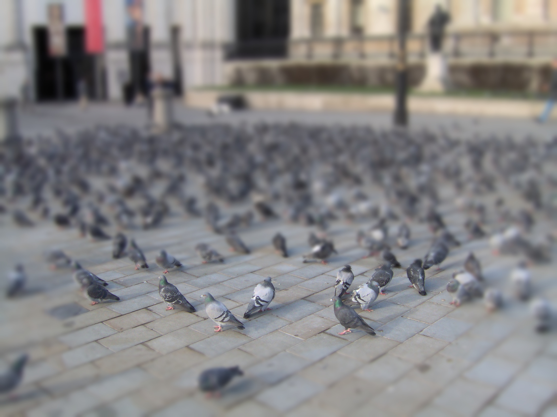
In this project, I created an effect similar to tilt shift that gives the impression that the lens is very close to the photograph's subject. It works by artificially decreasing the depth of field by blurring the image succesivly more in parts farther away from a specified region of focus.
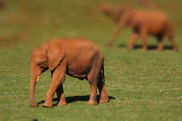
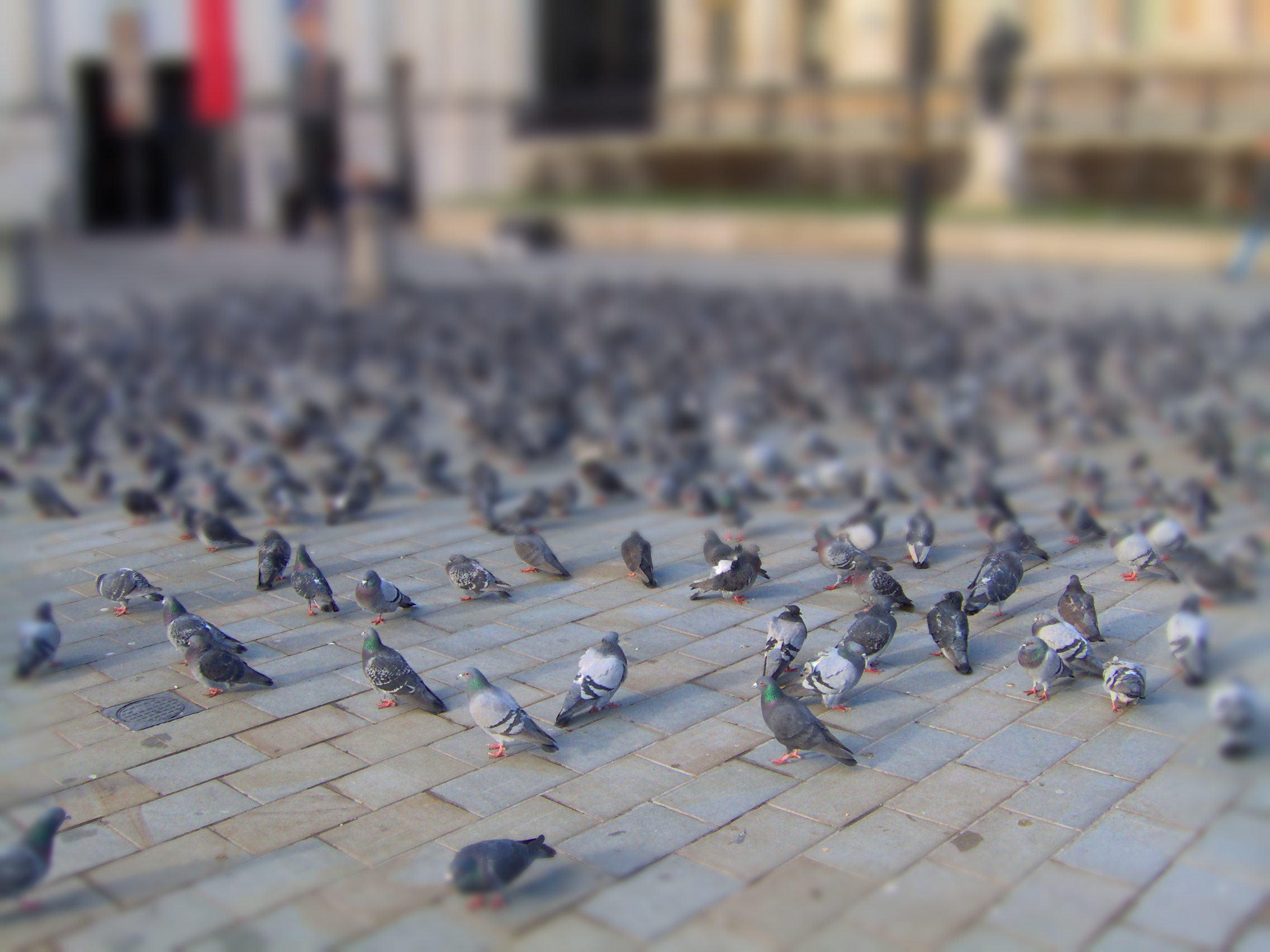
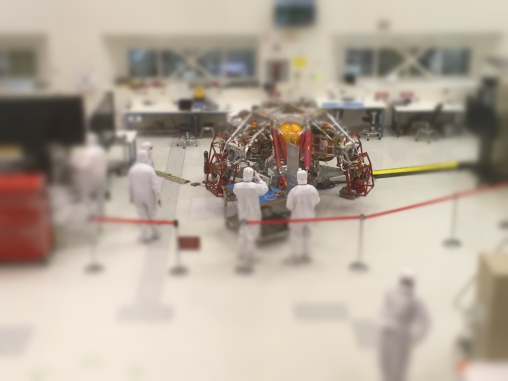
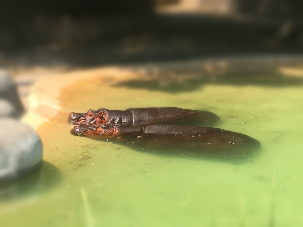
The simple way of defining a focus is either to use a point and have the blur radiate outwards, or to define a line and blur in thin rectangles radiating from that. The line works best of these two simple solutions because as mentioned in the description, as a rule of thumb, objects on the same line are at the same depth in the scene. Below is a comparison of using the point vs. line.
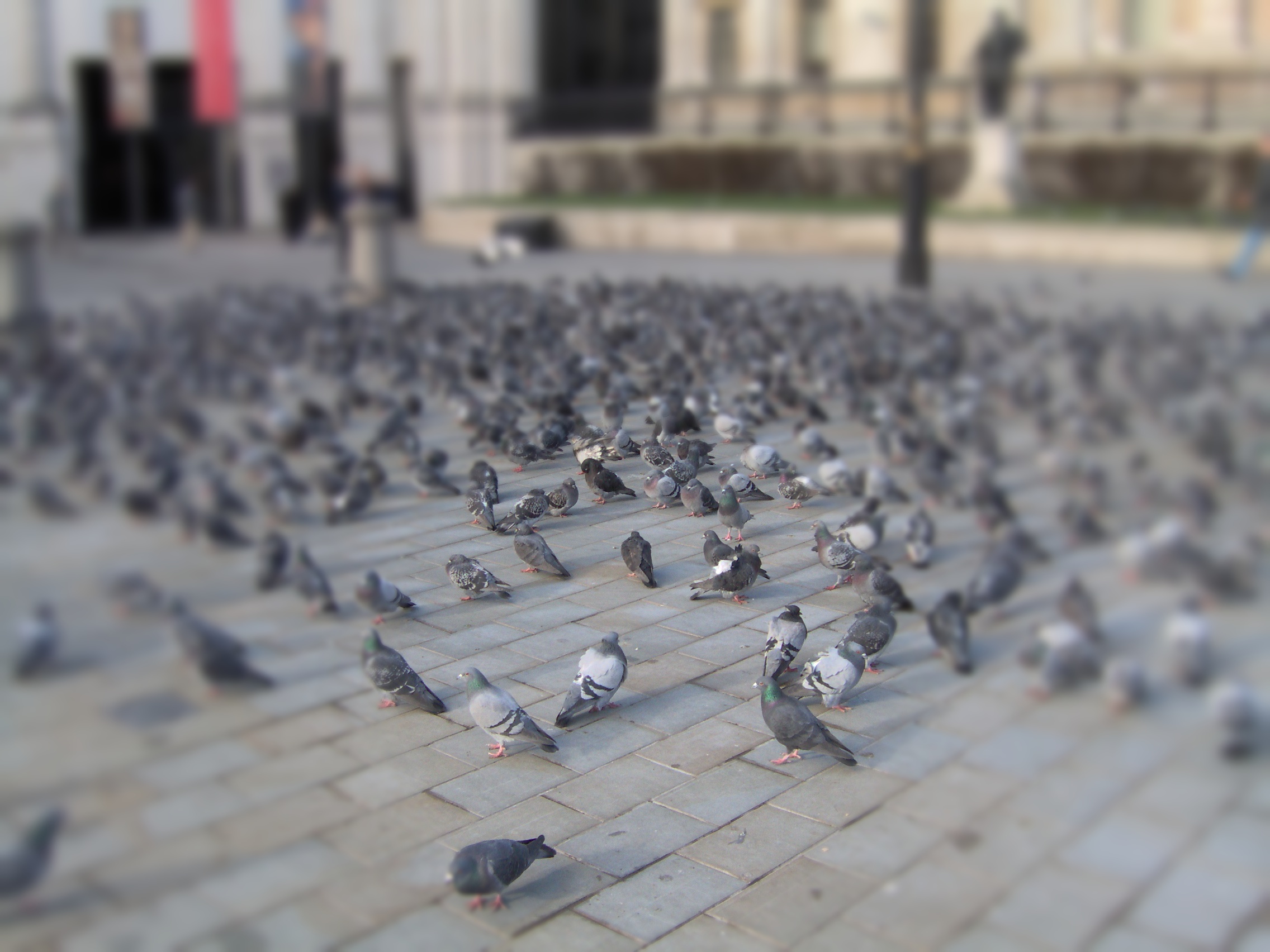

The successivly strong blur comes from creating a range of larger and larger shapes around the original and repeatedly applying the gaussian filter of a given strength. Here is an example of a few steps withing the iterations around a line.