Jazz Singh, September 2020
The Prokudin-Gorskii Photo Collection consists of sets of color channels produced from glass plate imaging; unfortunately, reconstructing a color image from these raw channels leads to noisy visual artifacts, stemming from a combination of positional and lighting-related misalignment. The objective of this project is to align these channels and recover clear photographs.
For more long-form background on the project, as well as information on the many techniques that can be applied to reduce visual artifacts in these images, see https://www.loc.gov/exhibits/empire/making.html.
In the majority of cases, tackling the positional misalignment issue in these photographs is sufficient towards producing clear results. We can re-frame the problem as an optimization problem where we attempt to shift two out of the three color channels to align with the third color channel; in other words, we are attempting to find the displacement vector (x, y) that optimizes a scoring function f.
Below, I've described my approach in solving this problem for low-resolution and high-resolution images.
A naive way approach to solving the above optimization problem is to search over a (reasonable) window of possible displacement vectors, for the vector that leads to the best alignment score. Using the Euclidean distance between each channel and a reference channel as the scoring function, this method indeed yields good results for low-resolution images. Pictures in the results section demonstrate this.
Note that I also experimented with the normalized cross-correlation score, which ended up yielding near-identical results.
Unfortunately, this naive method is far too slow for high-resolution images, as the window of possible displacement vectors is larger.
We can speed up our naive approach by using a bare-bones image pyramid: recursively find the best displacement vector for a smaller image scale; rescale this vector; and then refine the estimate to match the current resolution. This drastically decreases the time it takes to execute our algorithm on high-resolution images, from on the order of hours to ~10-15 seconds. Moreover, it ends up producing good results on all except one image. (This image contains lighting misalignment in addition to positional misalignment. See the Results section for more information.)
In more detail, the image pyramid approach to finding the best displacement vector consists of the following steps at each layer n.
I used the Euclidean distance as the scoring function for the image pyramid approach as well.
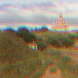
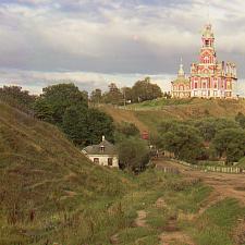
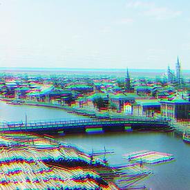
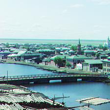
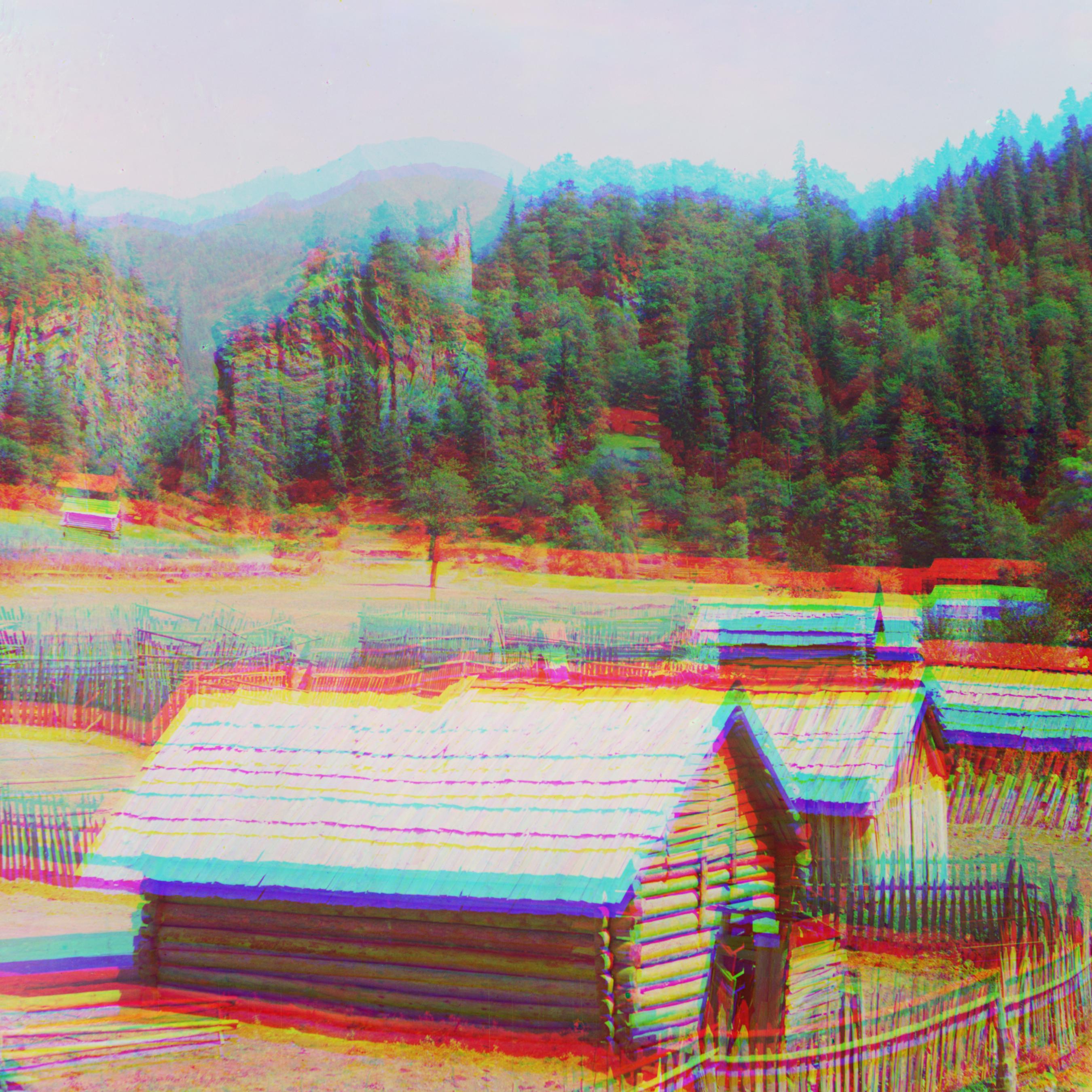
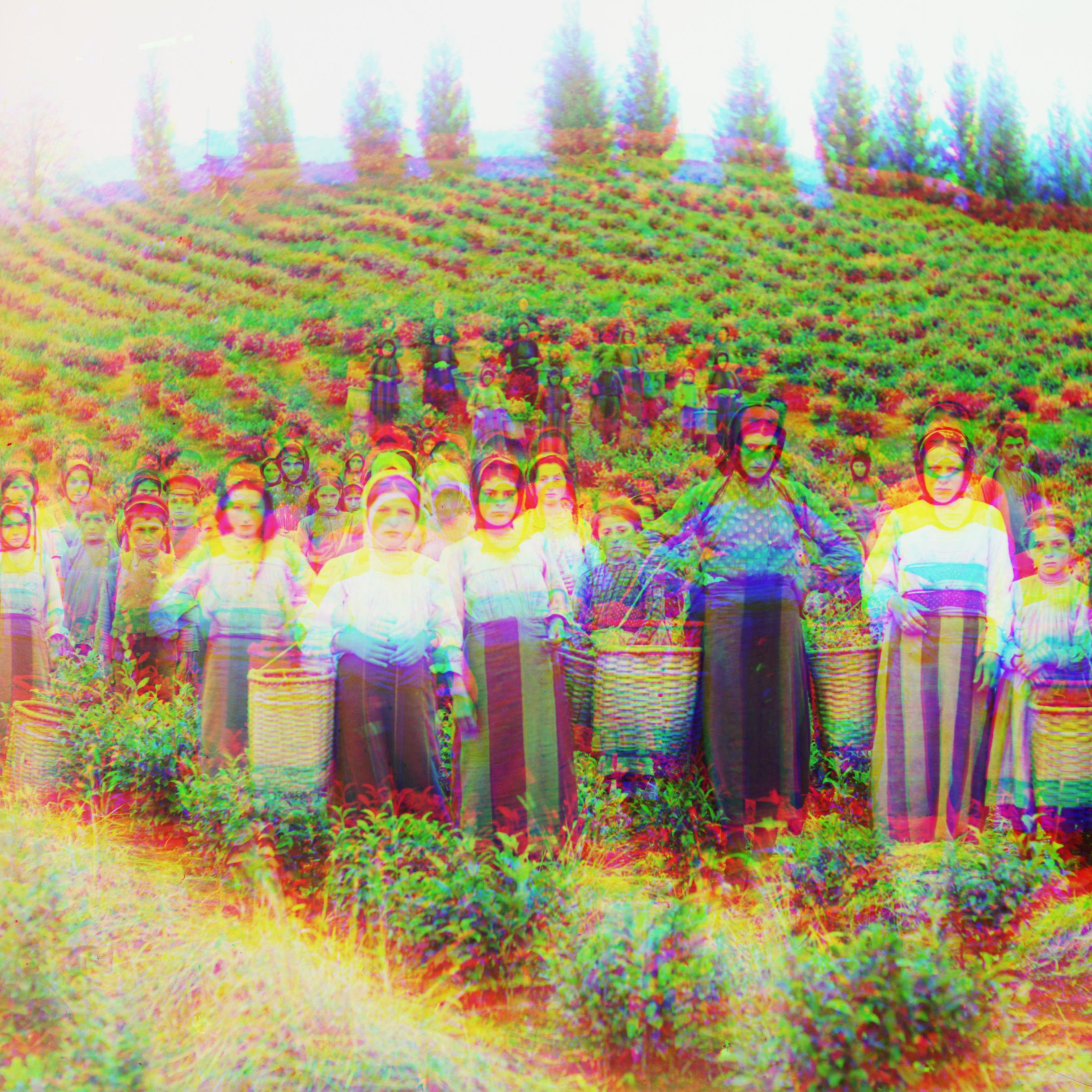
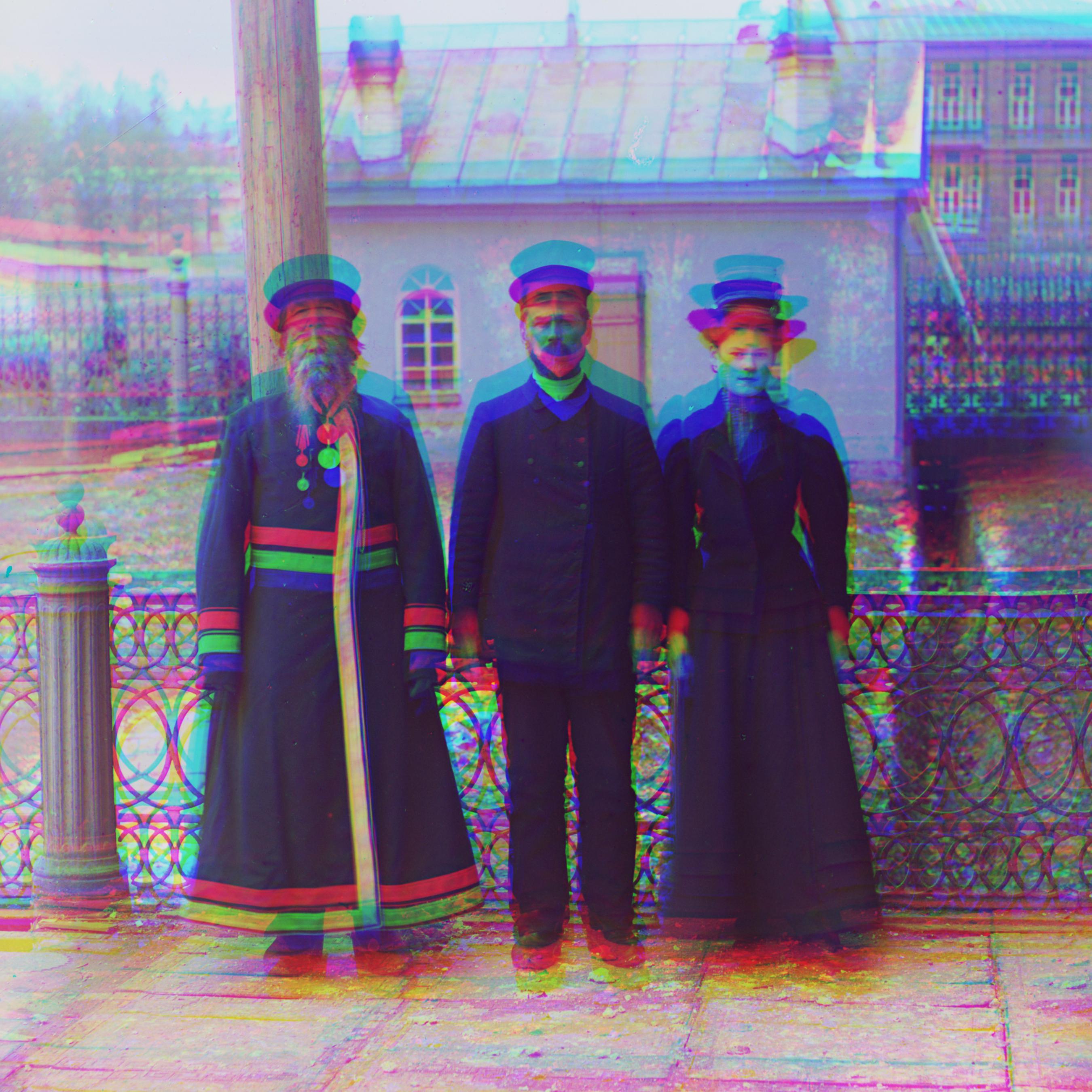
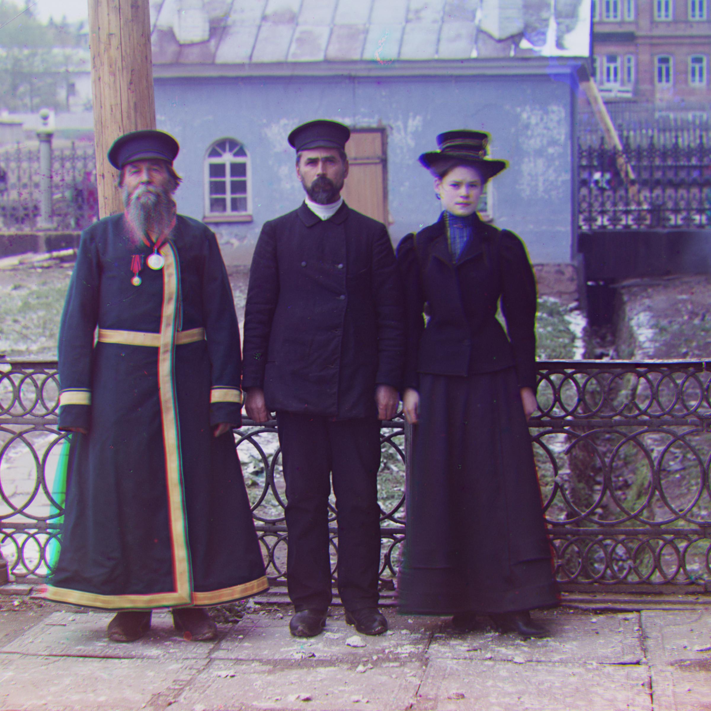
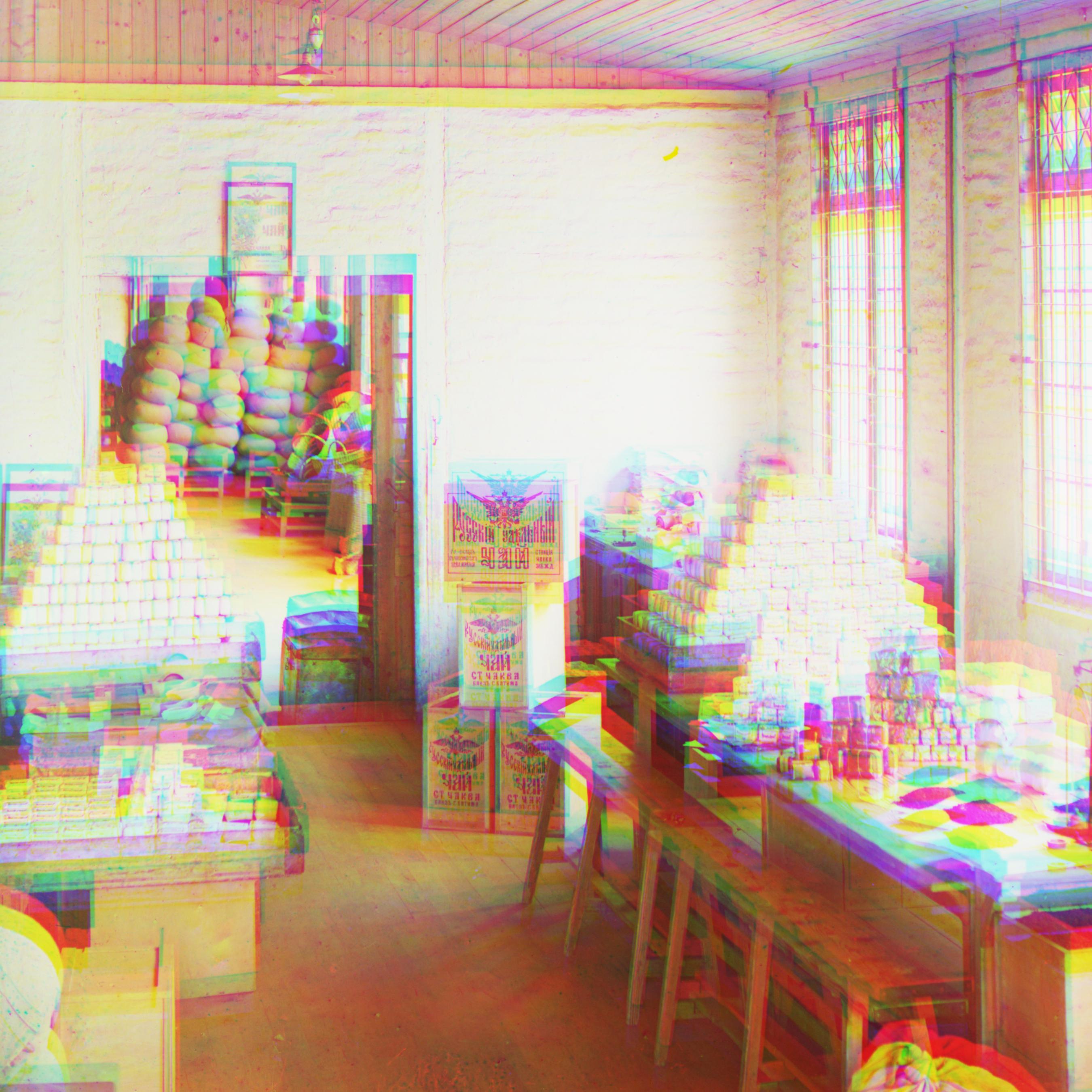
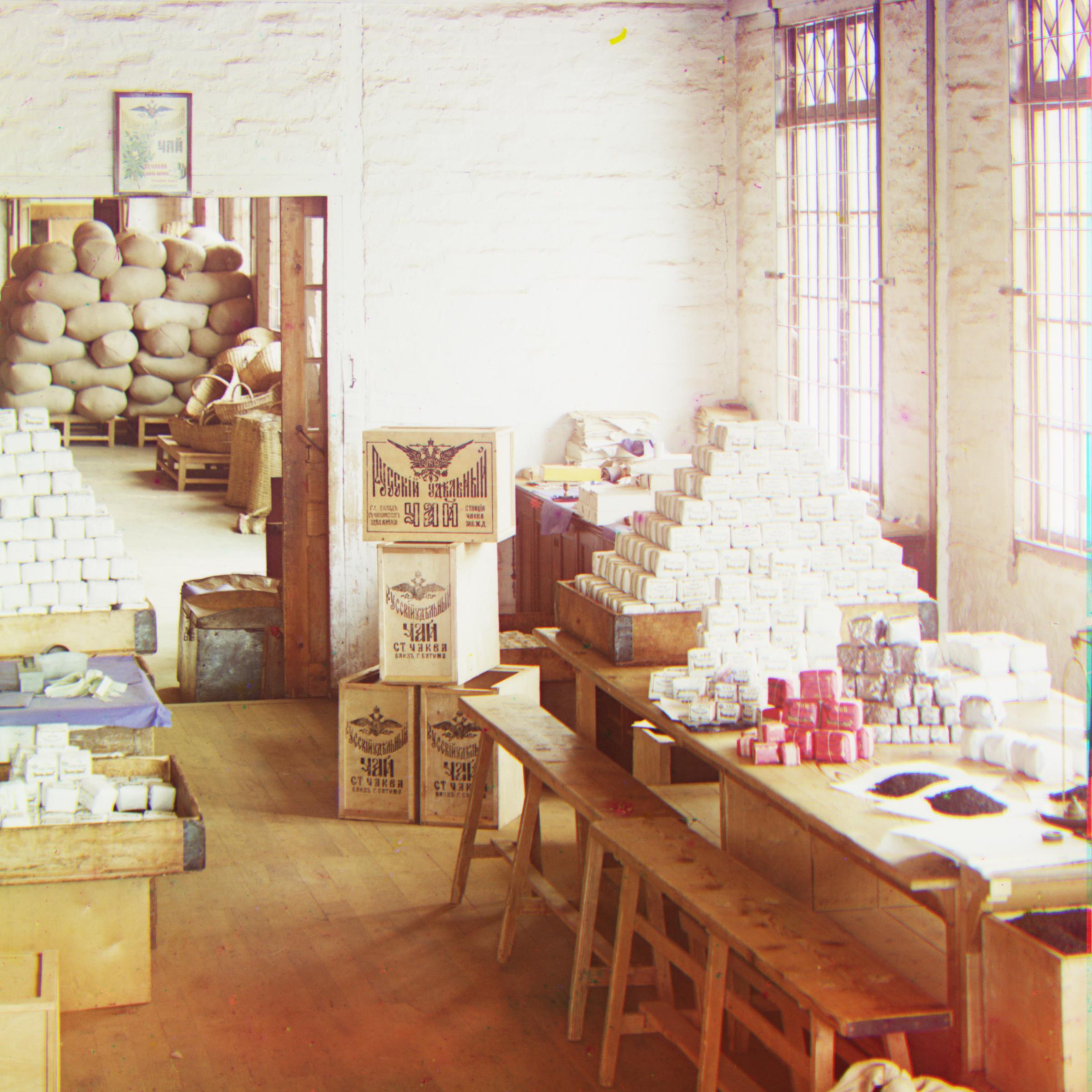
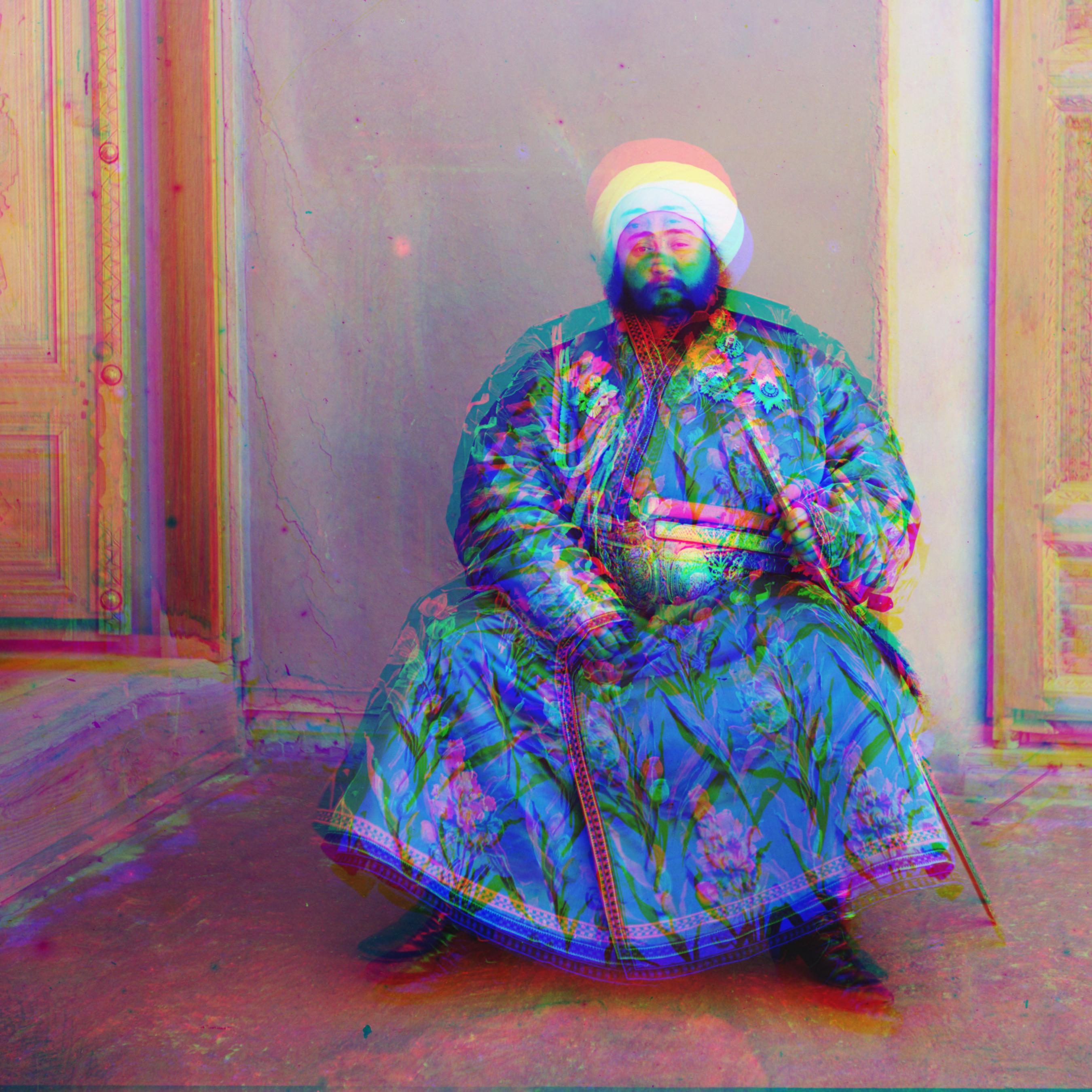
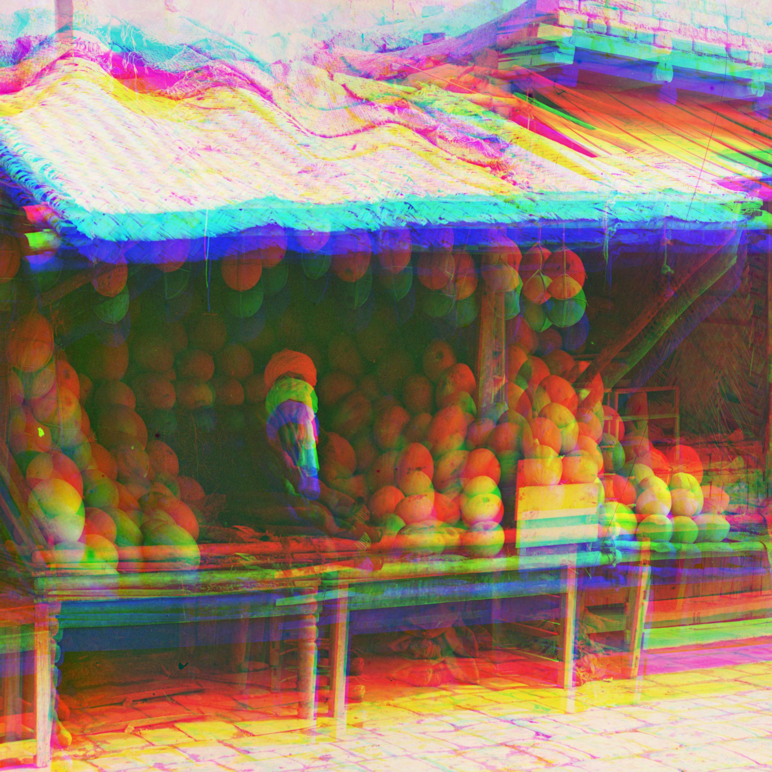
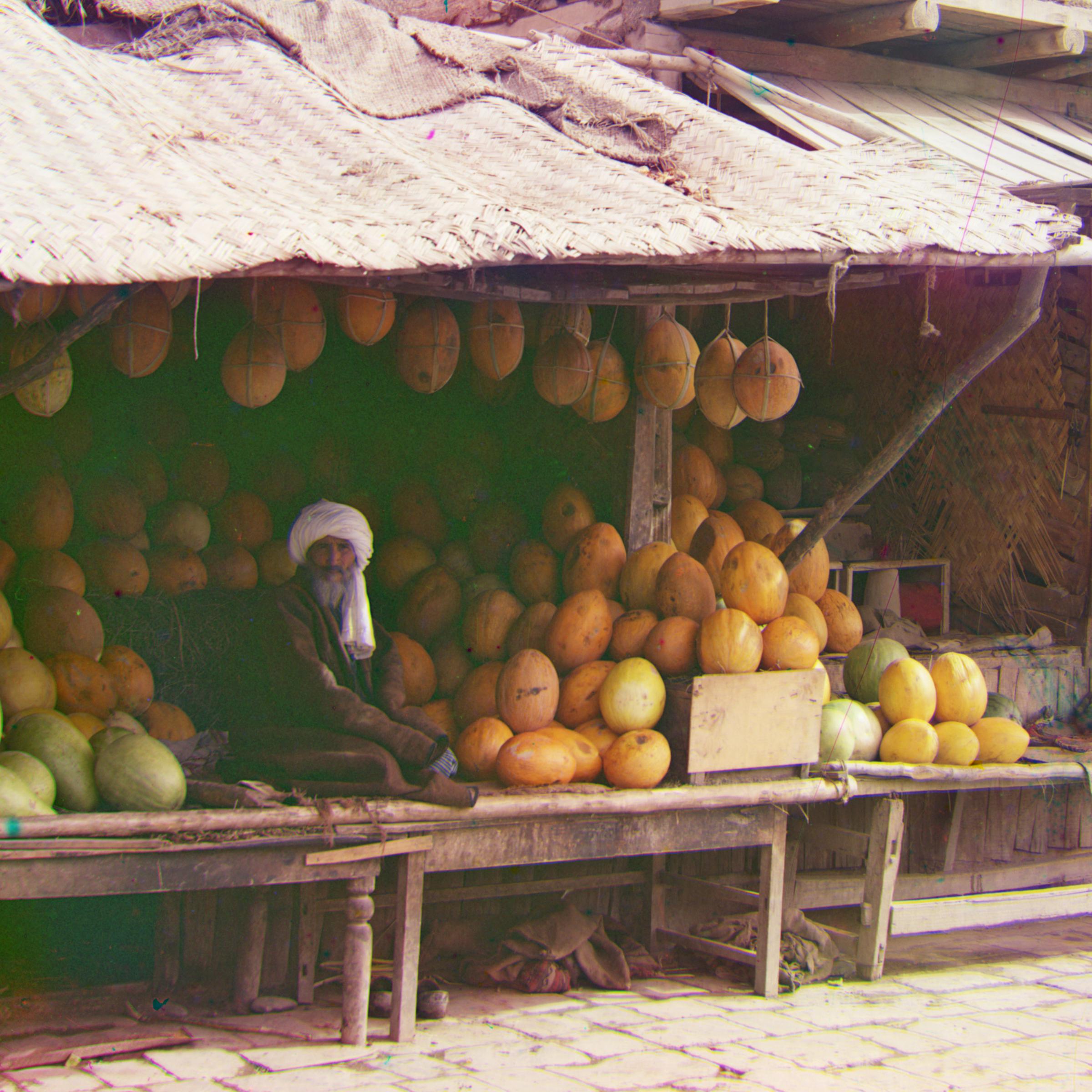
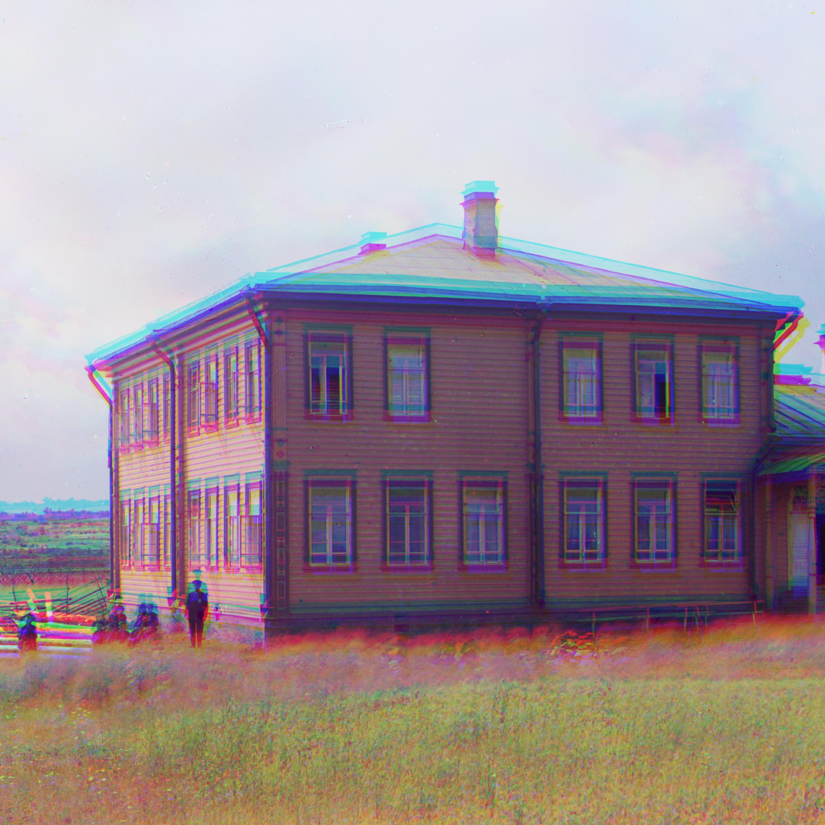
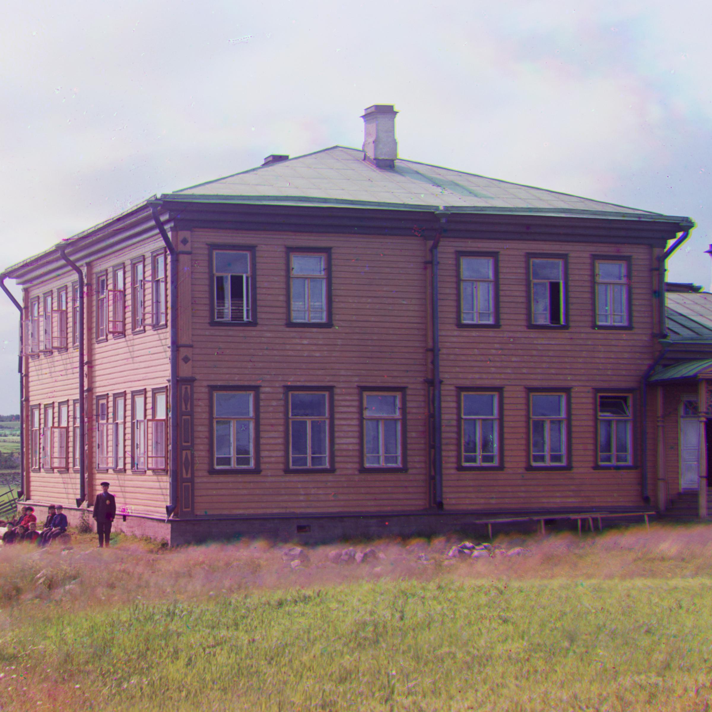
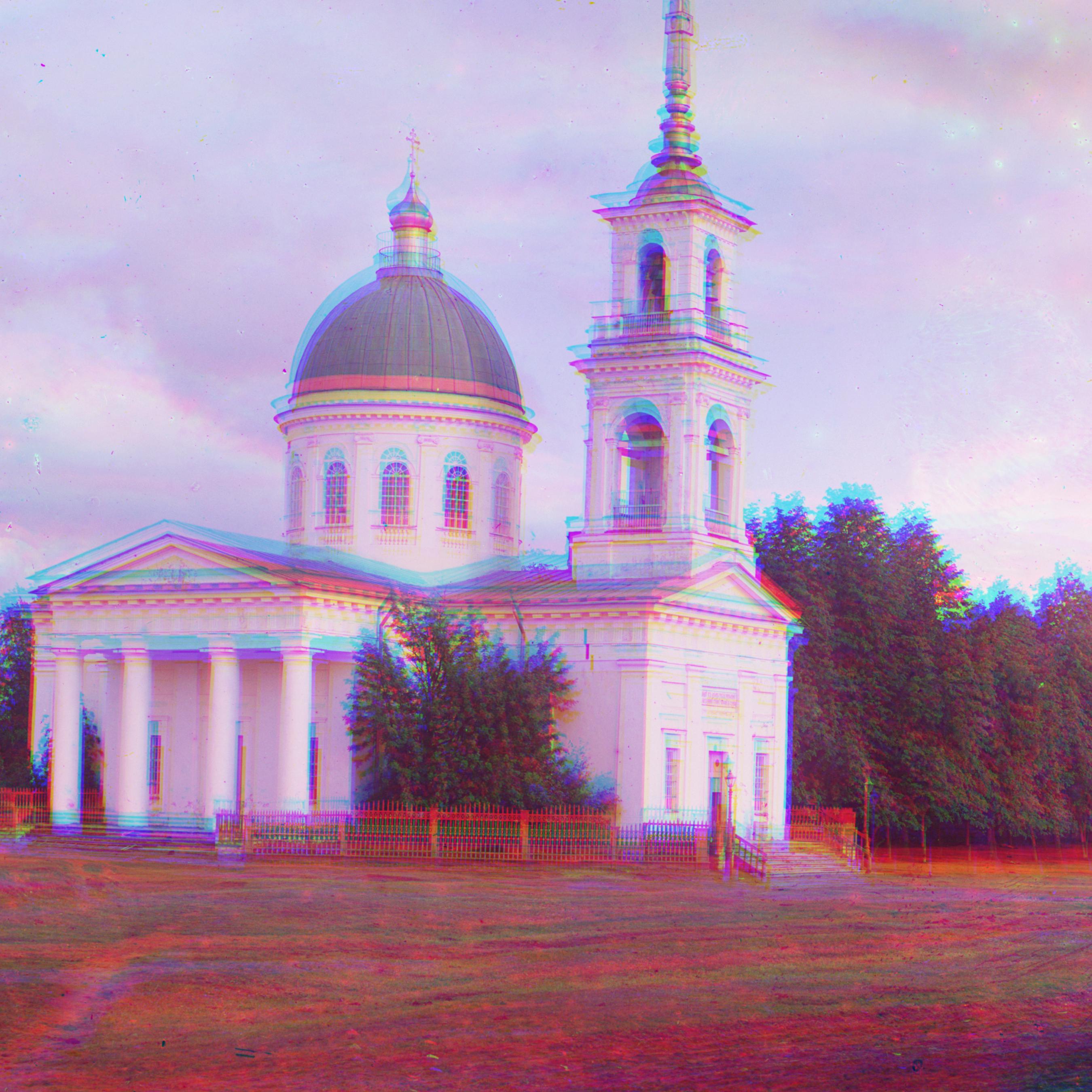
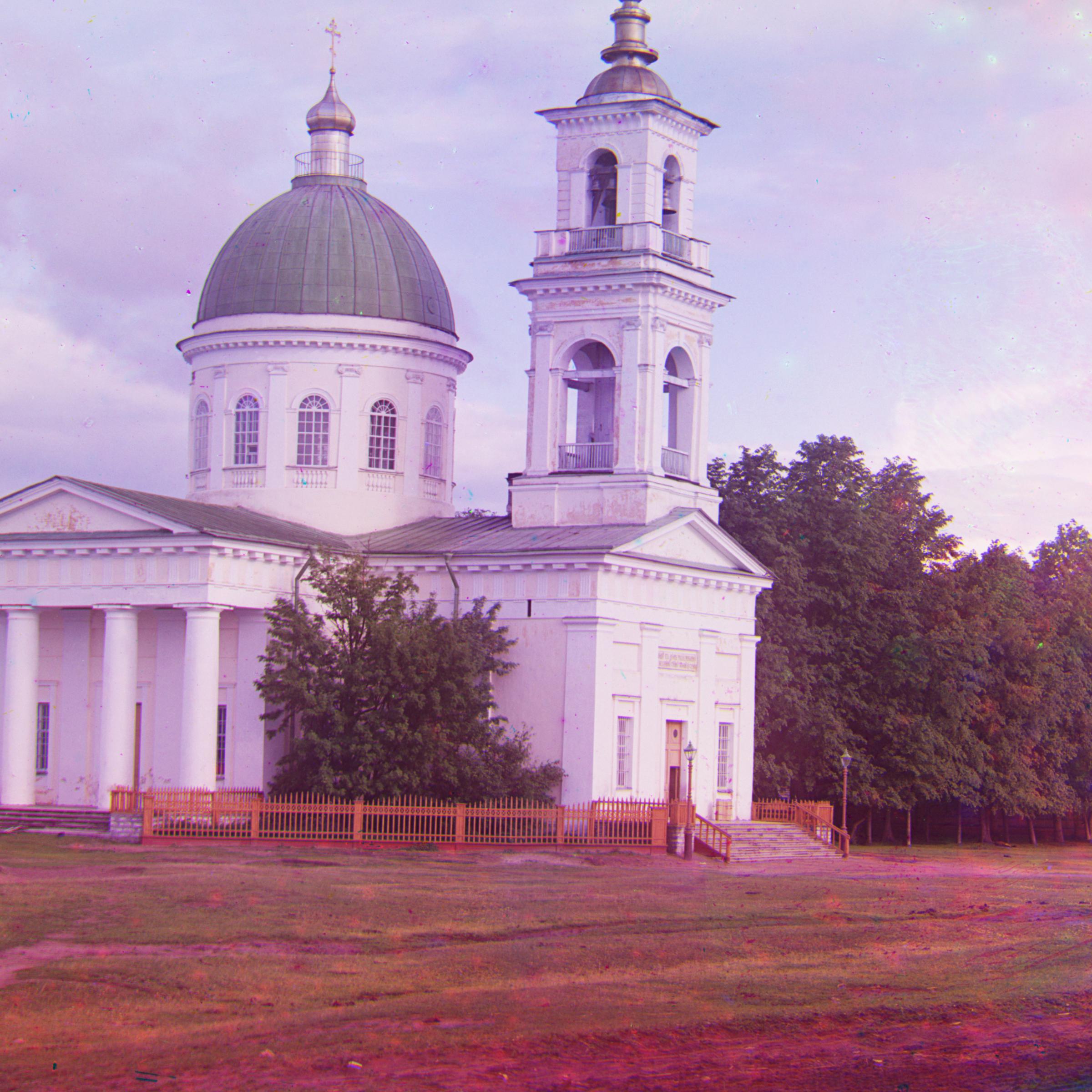
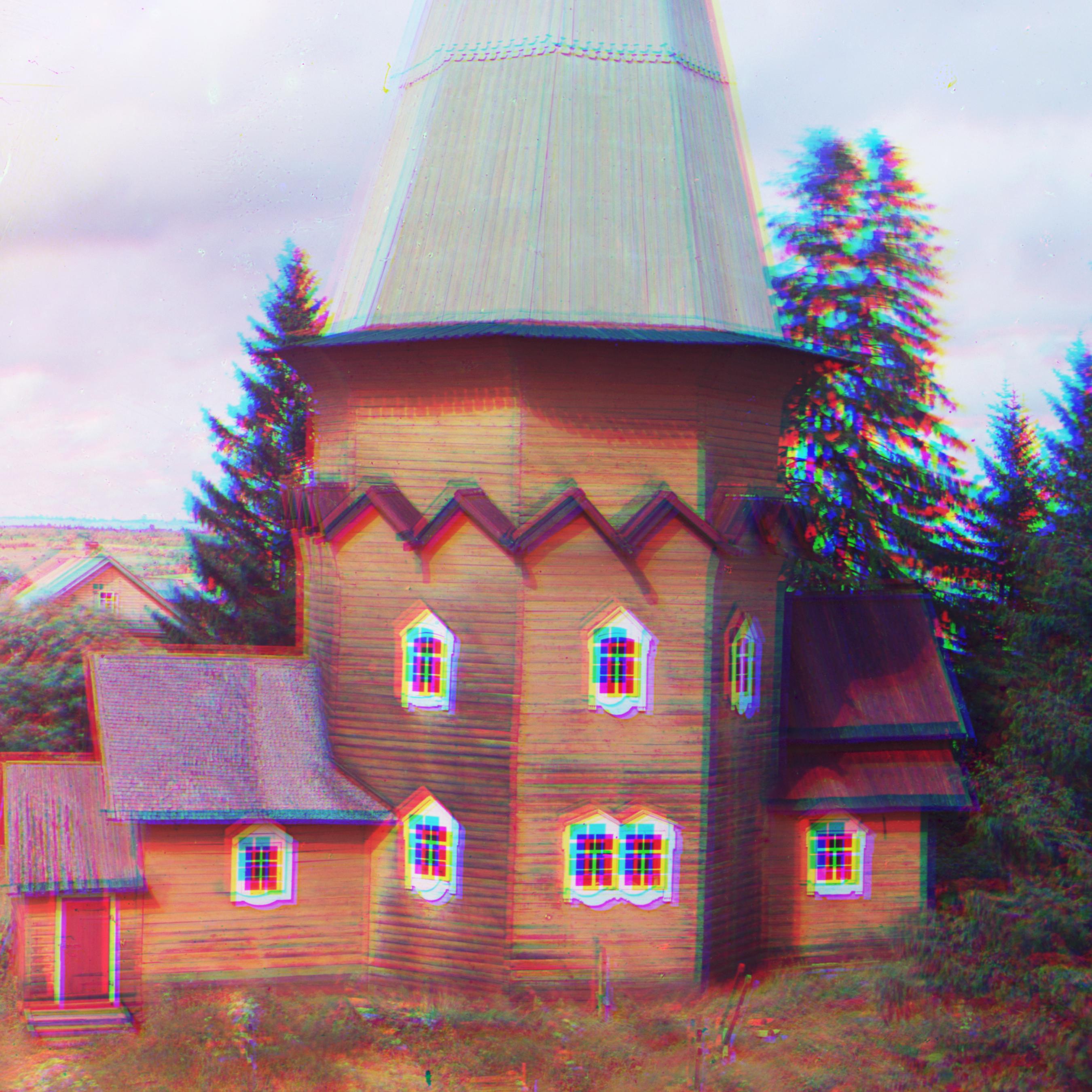
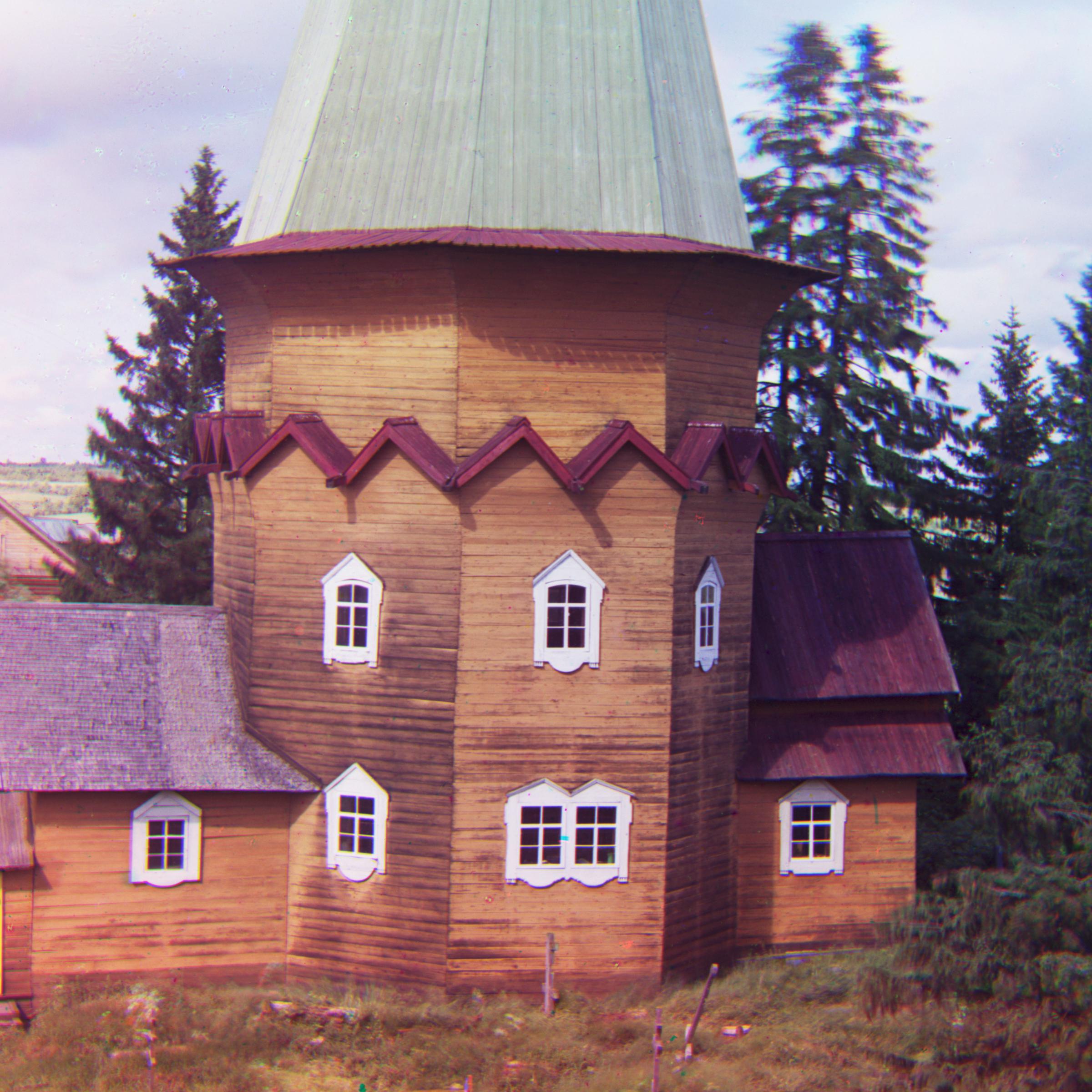
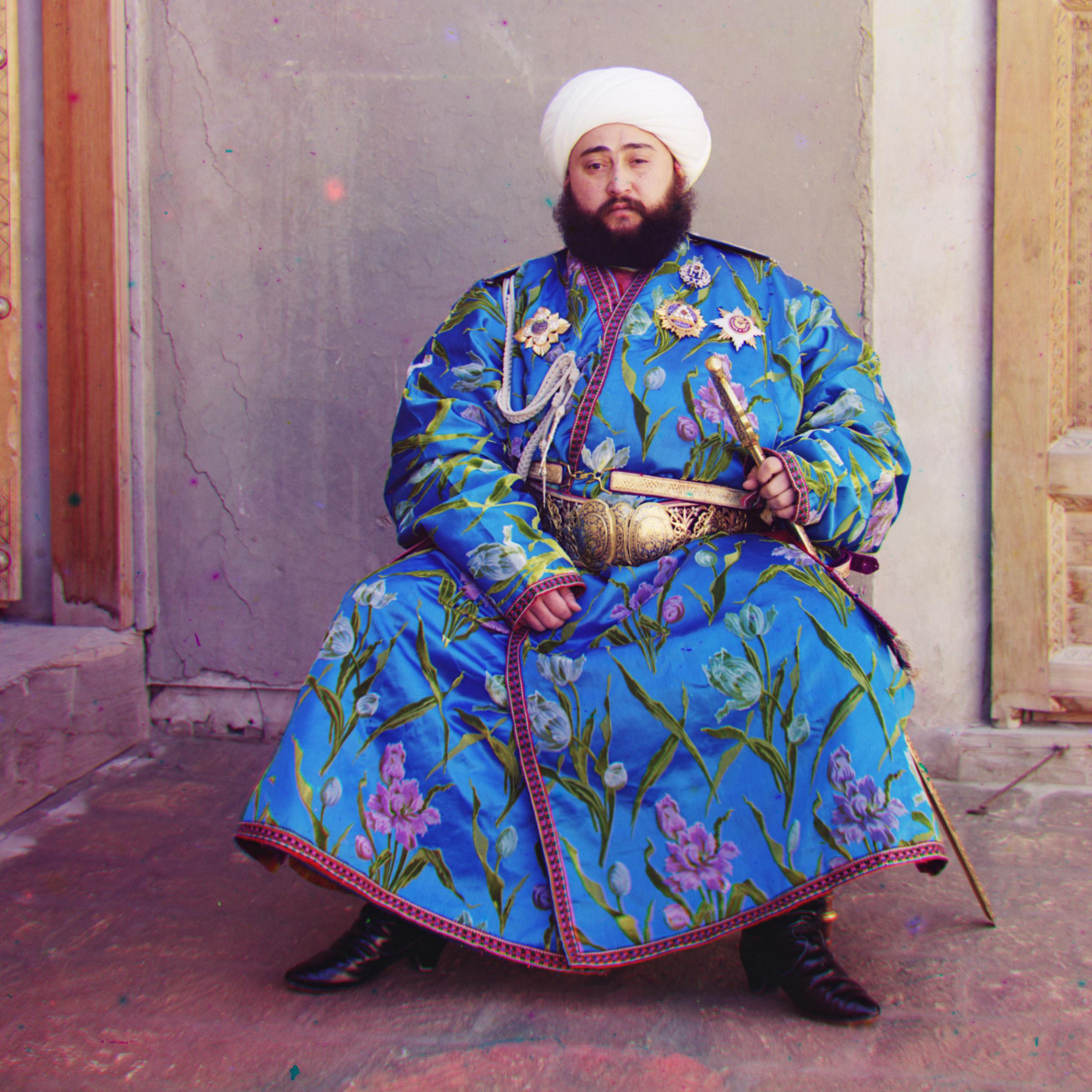
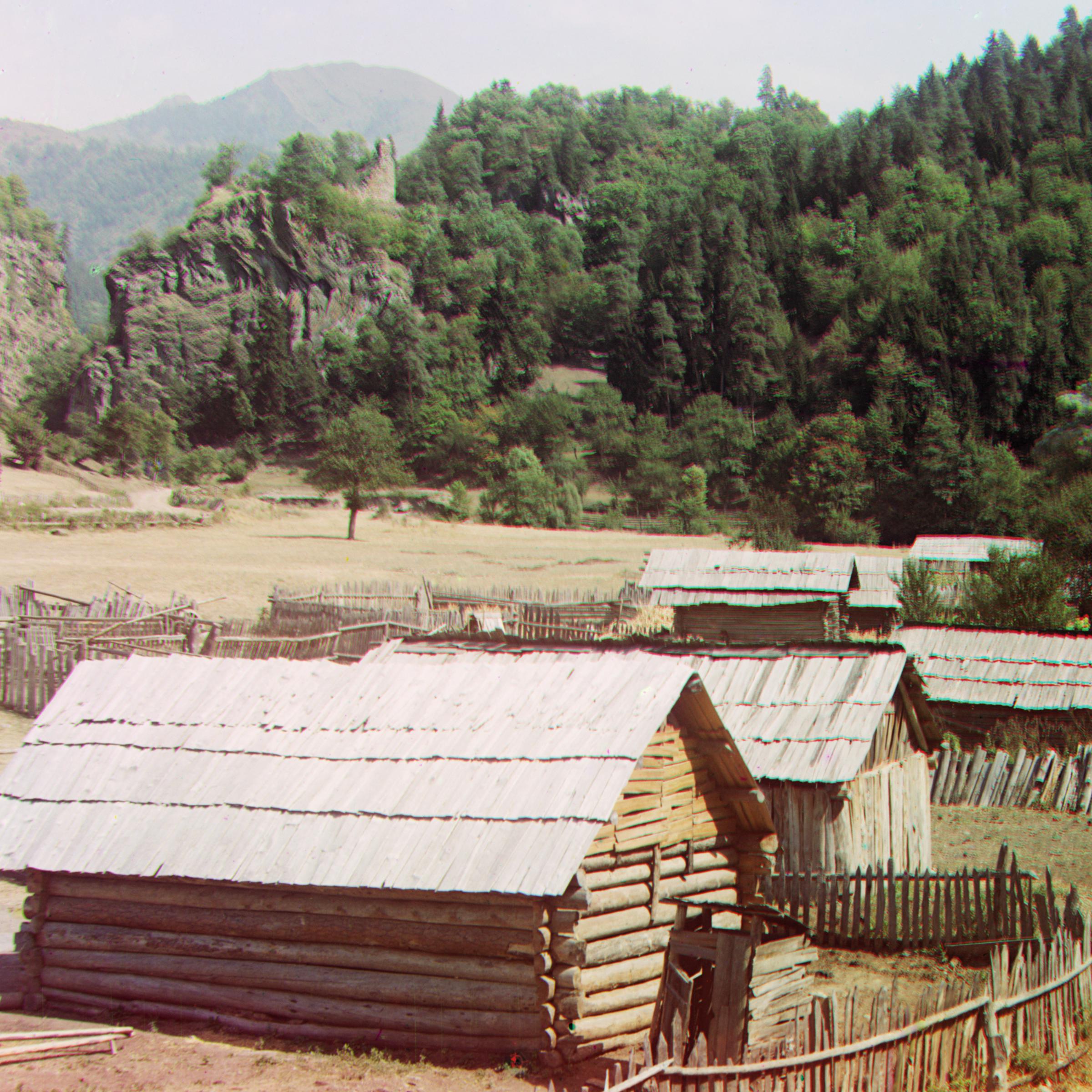
Below is a comparison of the original noisy and new aligned images side-by-side. I've included the displacement vector found by the above process for color channels R and G, where we let B be a reference channel. Notice, this approach fails on Emir; solving this issue is described in the Refinement section.
Note that the borders of the images were cropped out in pre-processing as well as post-processing stages. With respect to the former, this is because the large amount of noise at the borders of the input channels has an unwanted effect on optimization, so removing them leads to better results. With respect to the latter, aligning color channels via shifting results in slivers of visual noise at the borders.
The image names listed are taken from the original data collection, linked above.
|
|
|
|
|
|
|||||
|---|---|---|---|---|---|---|---|---|---|---|
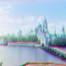
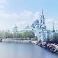
| Cathedral | Aligned, R: (12, 3), G: (5, 2) | Monastery | Aligned, R: (3, 2), G: (-3, 2) | Tobolsk | Aligned, R: (6, 3), G: (3, 2) |
 |
 |
 |
 |
 |
 |
|||||
|---|---|---|---|---|---|---|---|---|---|---|
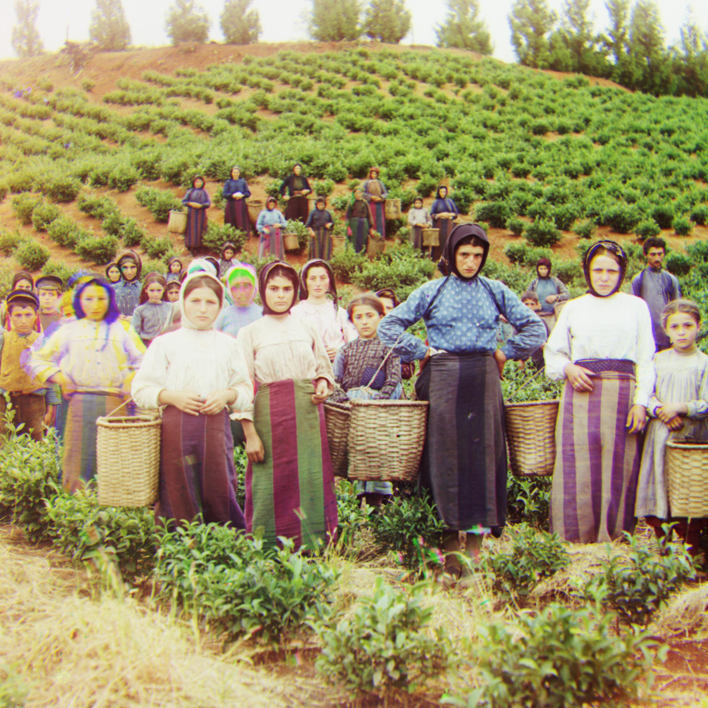
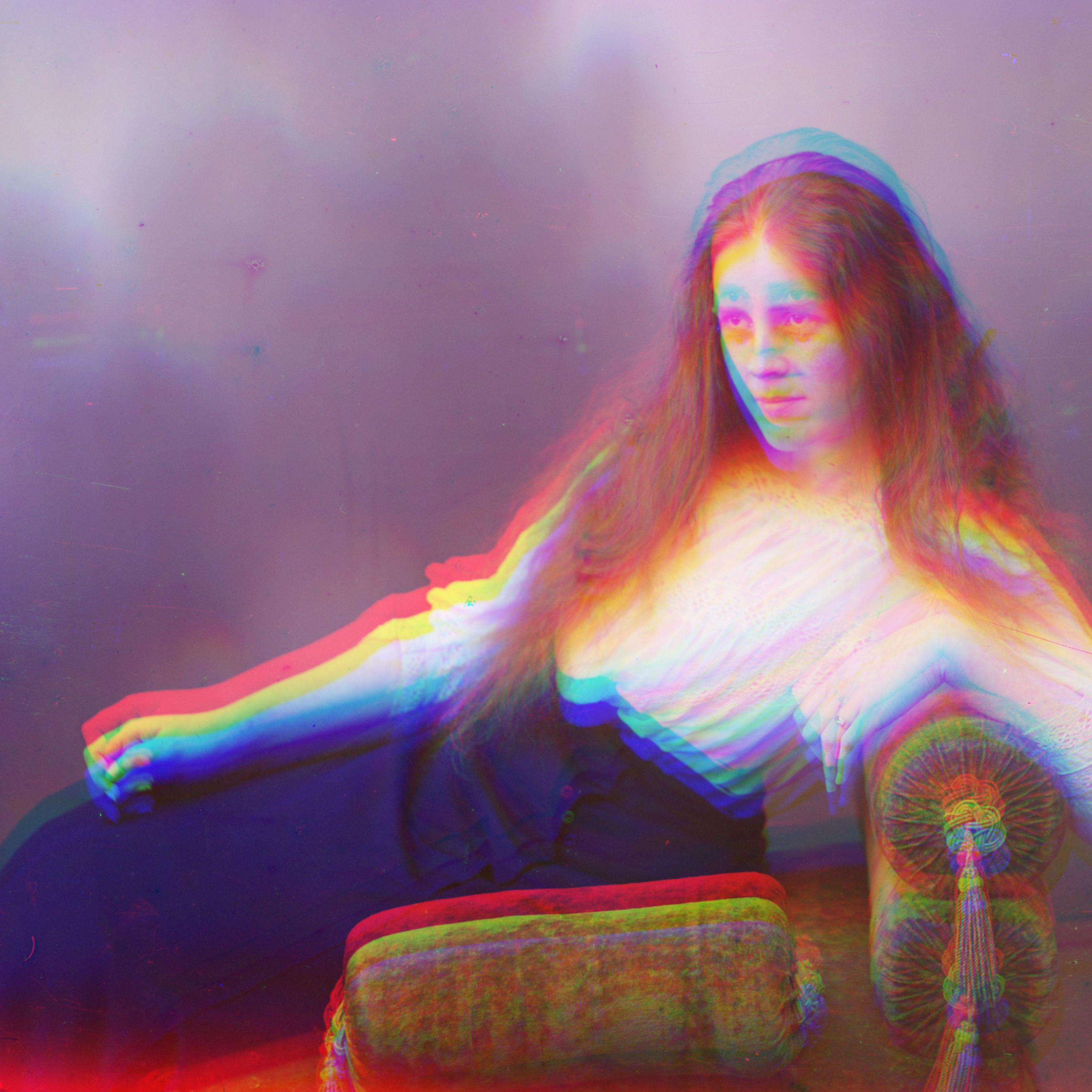
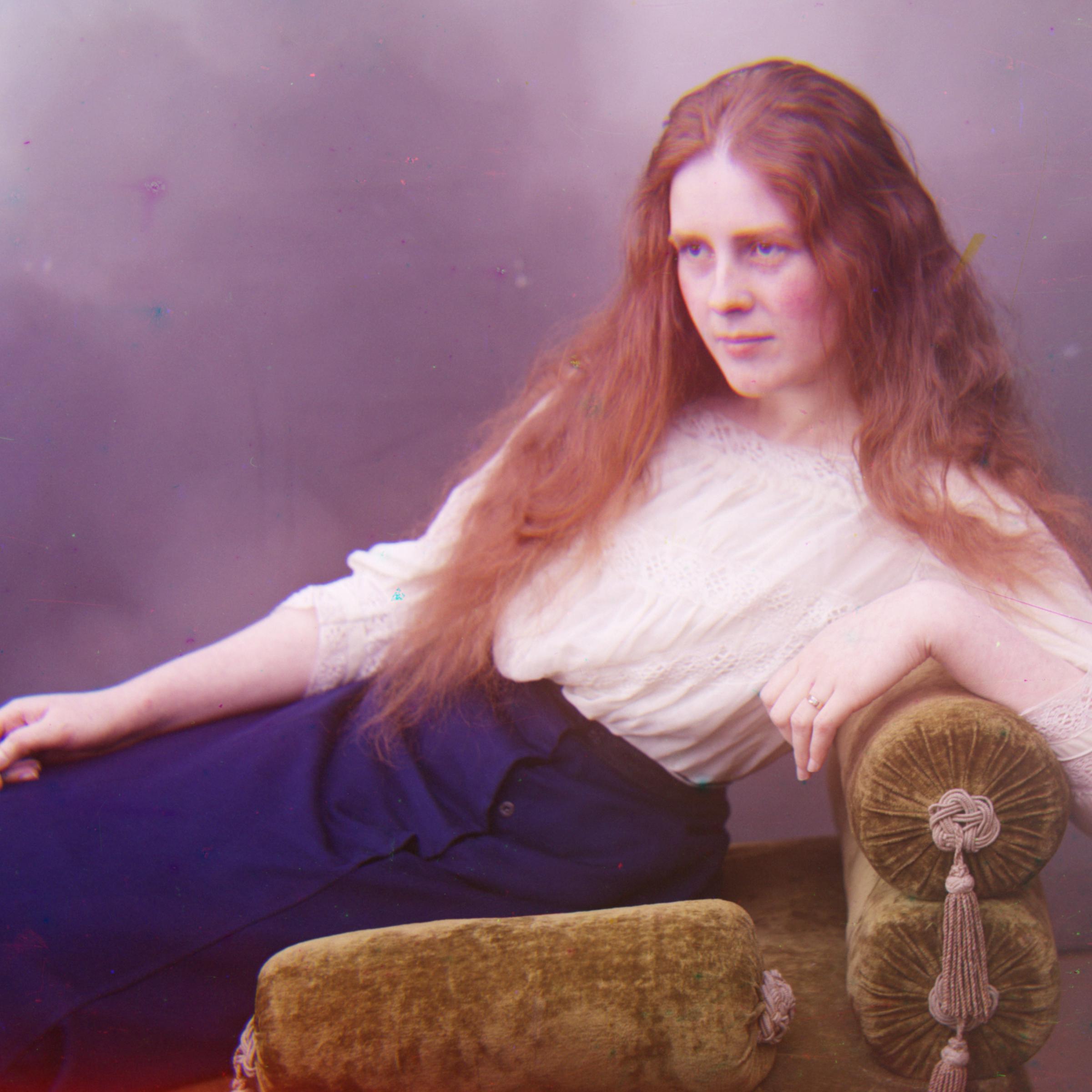
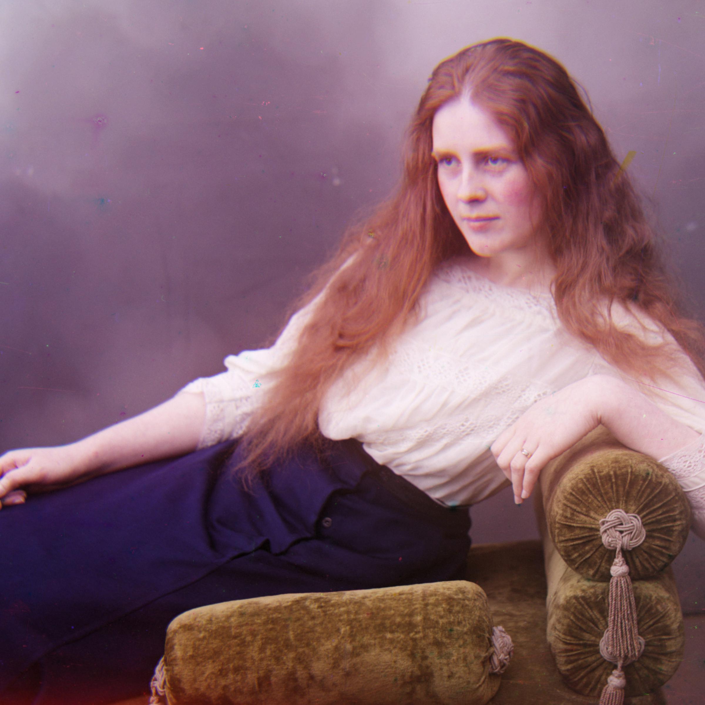
| Castle | Aligned, R: (97, 4), G: (35, 2) | Harvesters | Aligned, R: (123, 13), G: (59, 16) | Lady | Aligned, R: (113, 11), G: (49, 8) |
 |
 |
 |
 |
 |
 |
|||||
|---|---|---|---|---|---|---|---|---|---|---|
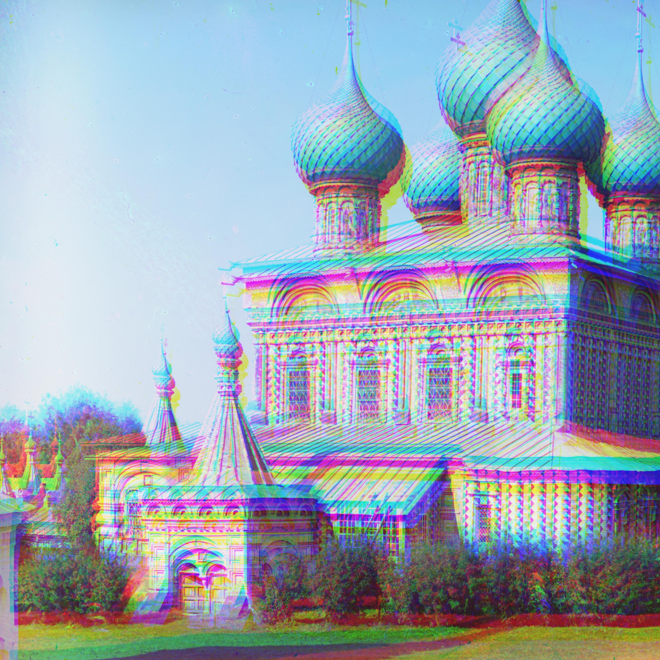
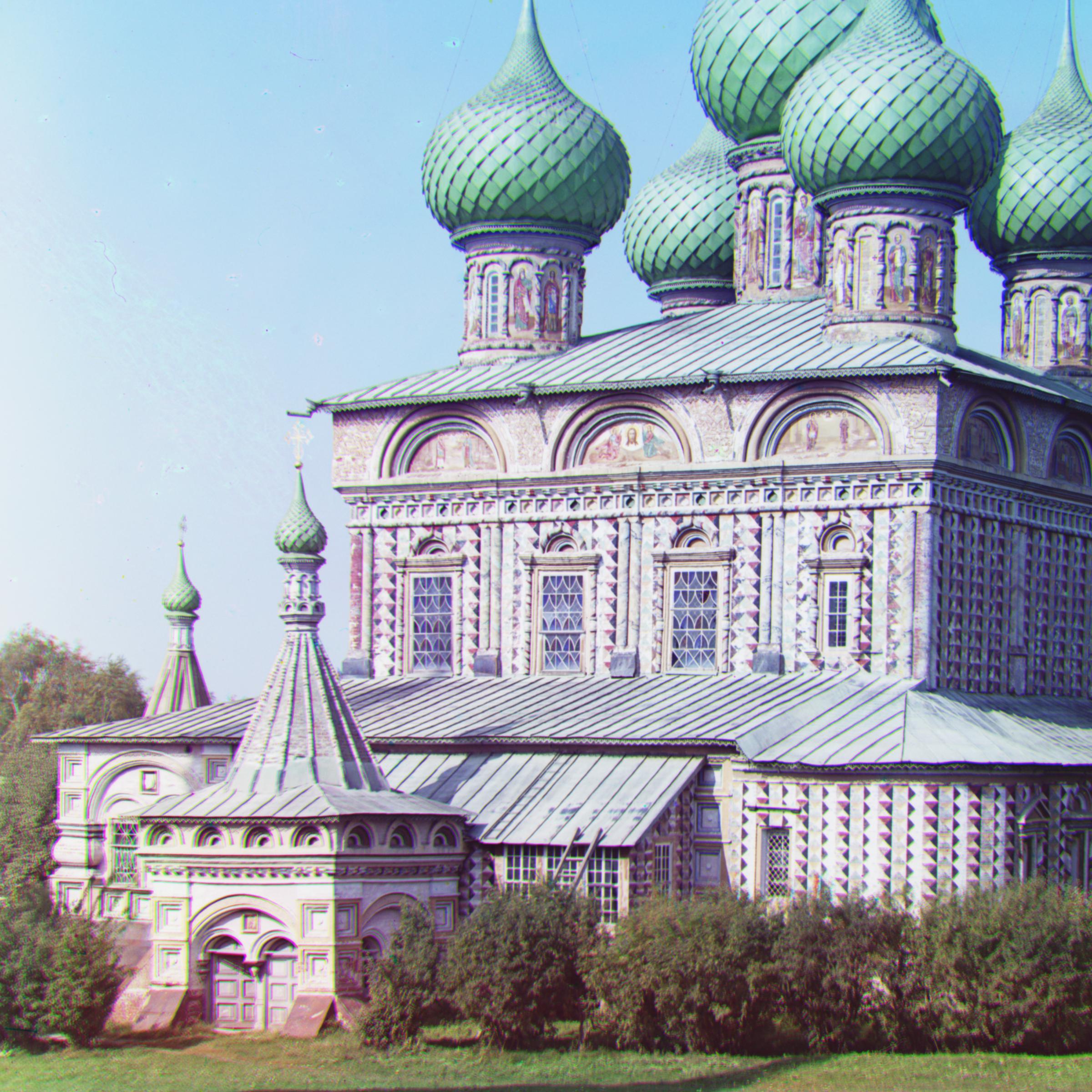
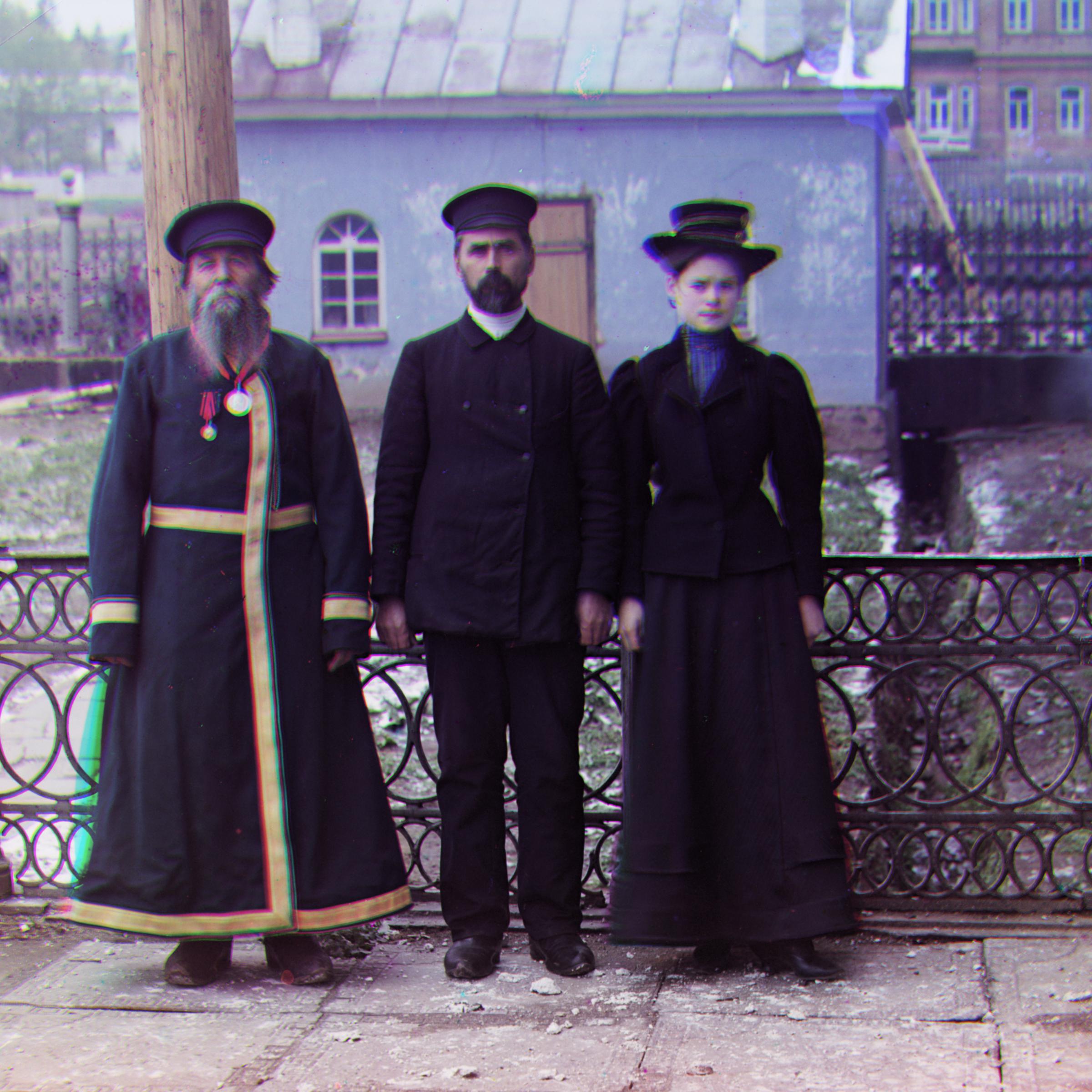
| Onion Church | Aligned, R: (108, 36), G: (51, 26) | Three Generations | Aligned, R: (110, 10), G: (52, 13) | Workshop | Aligned, R: (103, -12), G: (52, -1) |
 |
 |
 |
 |
|||||||
|---|---|---|---|---|---|---|---|---|---|---|
| Emir | Aligned, R: (132, -282), G: (49, 24) | Icon | Aligned, R: (89, 22), G: (40, 17) | Melons | Aligned, R: (178, 12), G: (81, 9) |
 |
 |
 |
 |
|||
|---|---|---|---|---|---|---|
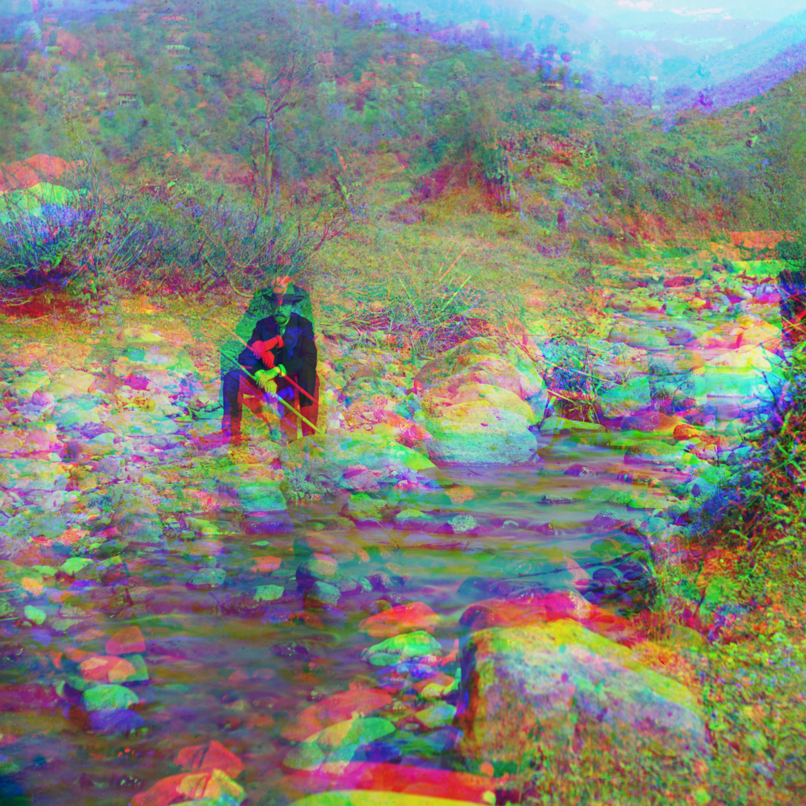
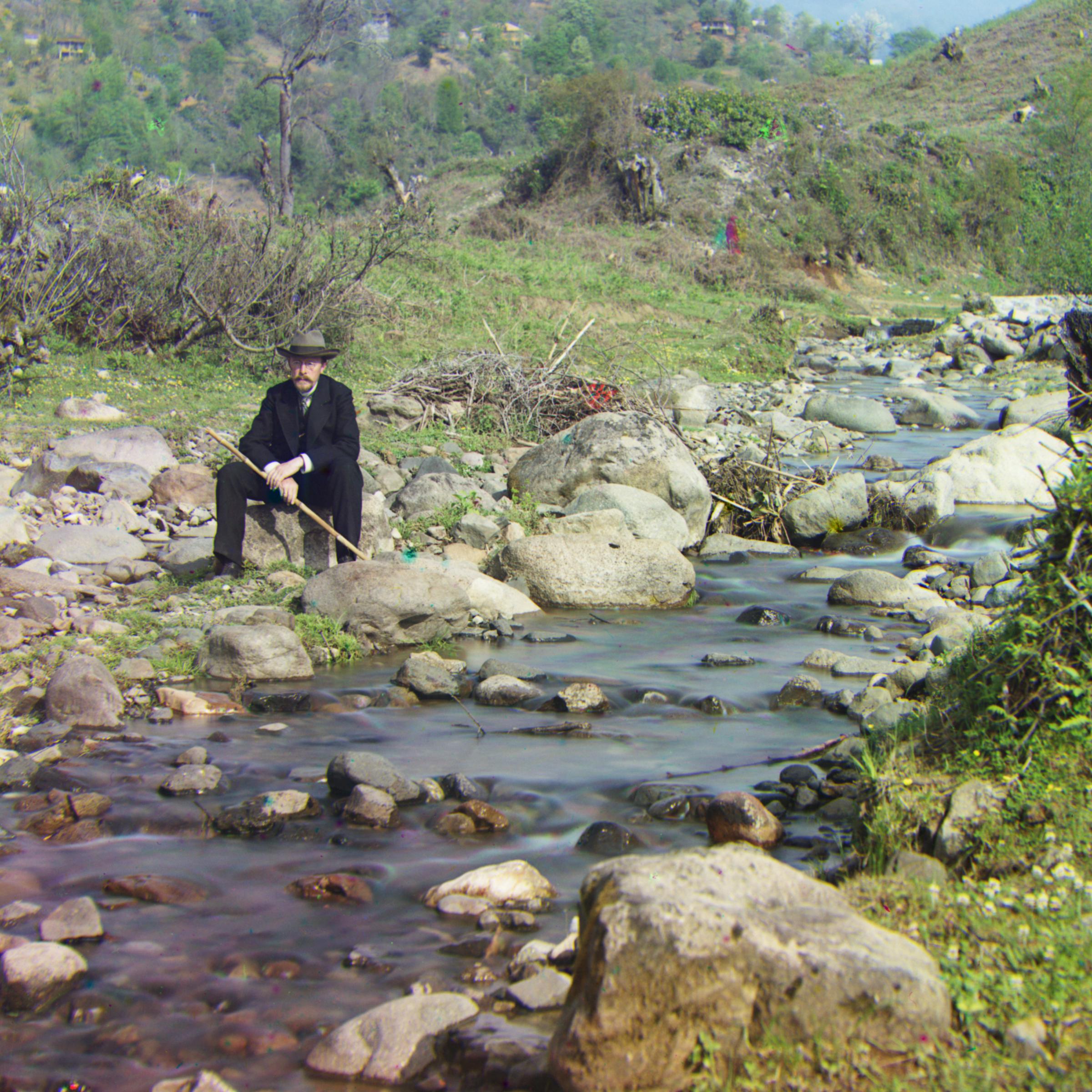
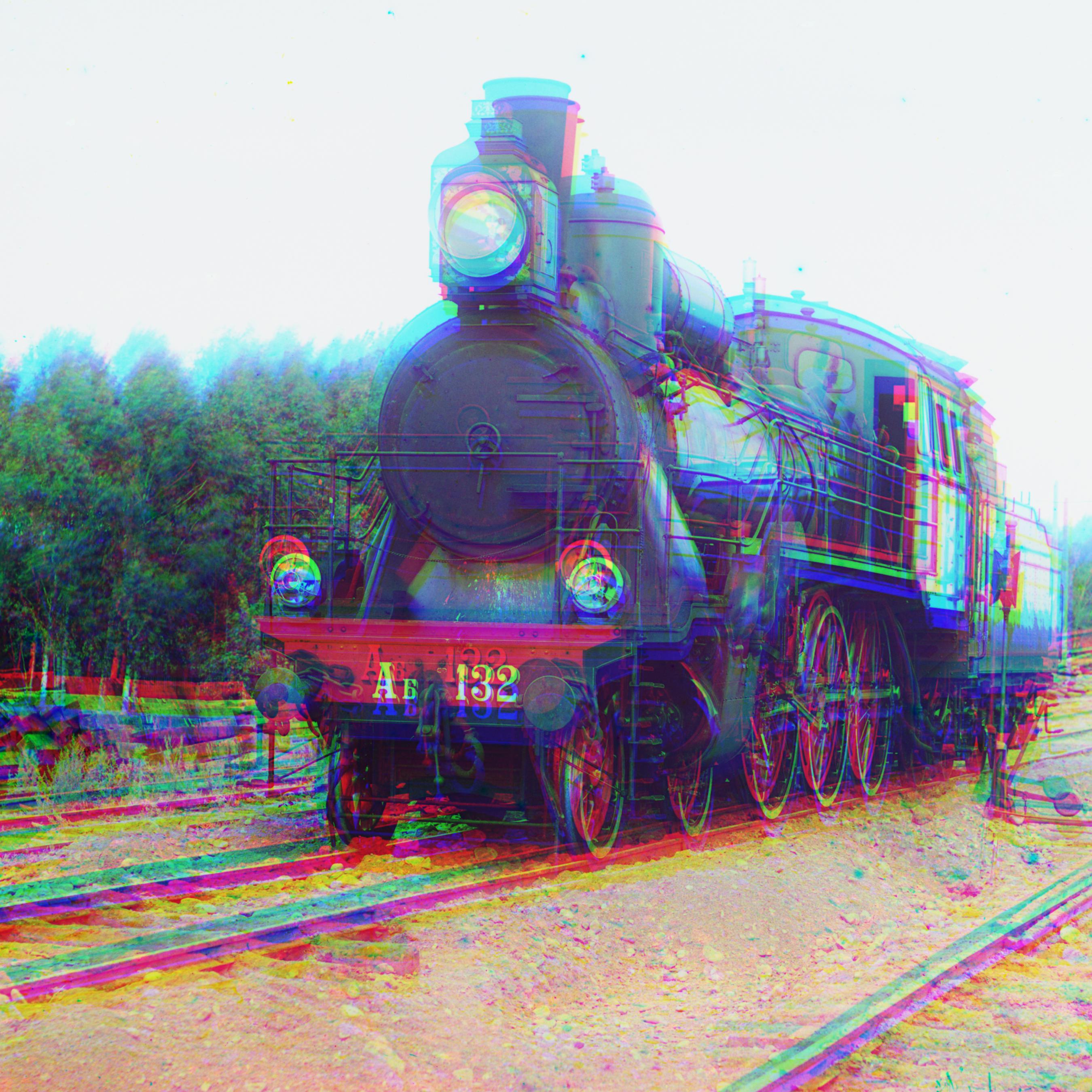
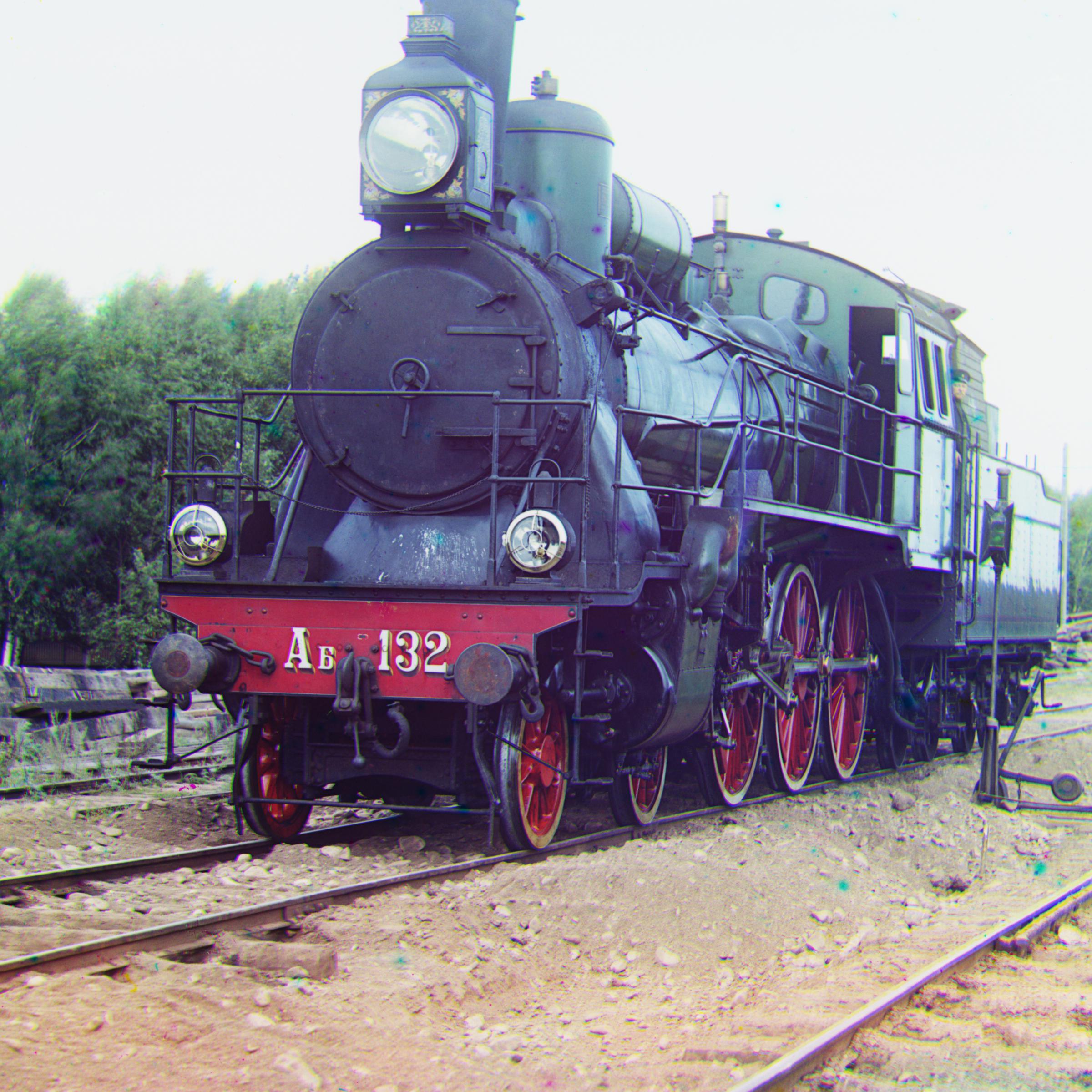
| Self Portrait | Aligned, R: (174, 36), G: (77, 28) | Train | Aligned, R: (86, 31), G: (42, 5) |
 |
 |
 |
 |
 |
 |
|||||
|---|---|---|---|---|---|---|---|---|---|---|
| Bonus 1 | Aligned, R: (62, 9), G: (26, 9) | Bonus 2 | Aligned, R: (63, 16), G: (25, 11) | Bonus 3 | Aligned, R: (35, 38), G: (9, 19) |
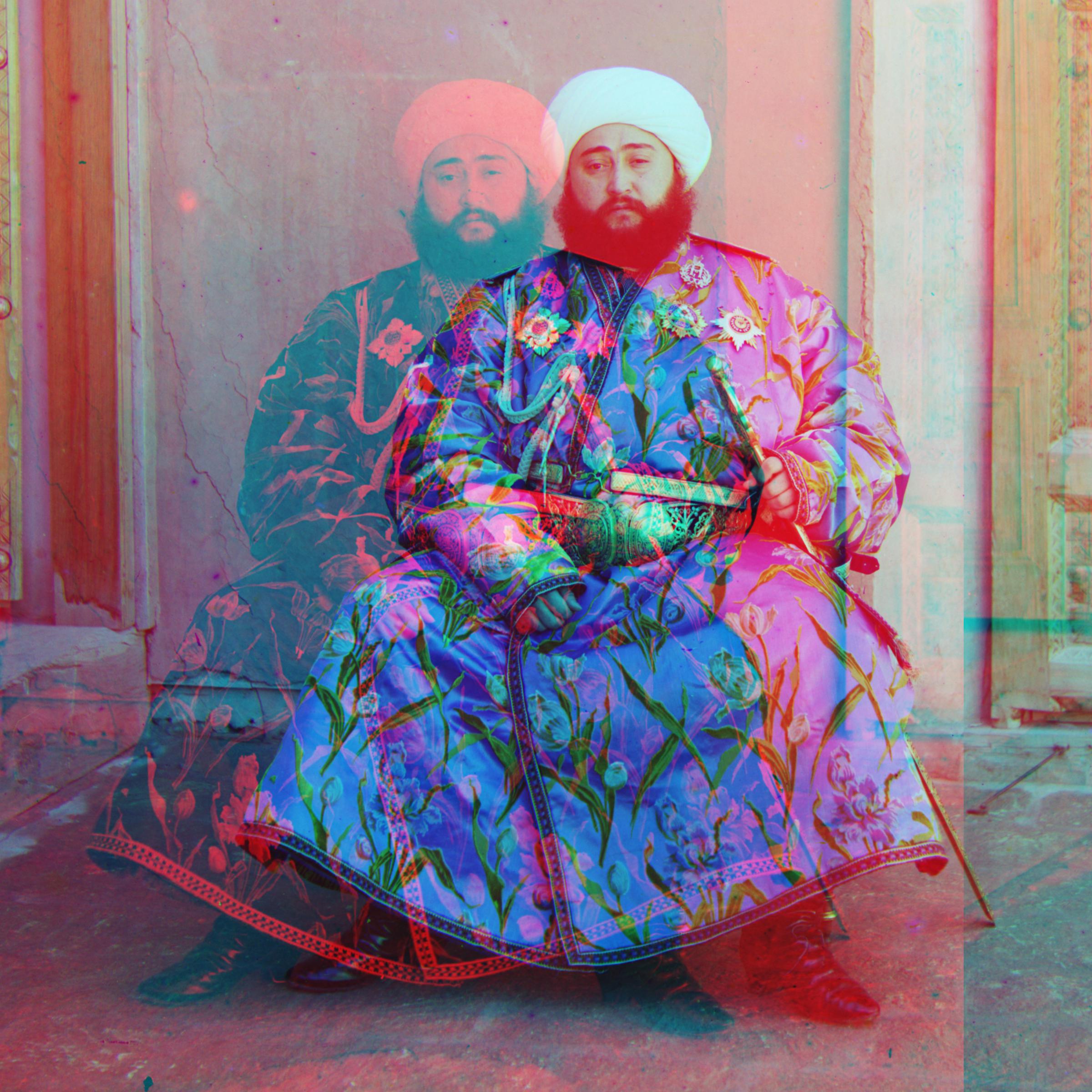
The above approach appears to produce very clear images with few if any visual artifacts, on all of the images except for emir. This is because there is brightness inconsistency in addition to positional inconsistency between channels in emir.
A better choice of image features resolves this issue. Switching from raw RGB pixels as our representation of input channels to edges (as found by the Canny edge detection algorithm) leads to this much better emir alignment:
|
 |
|
|---|---|---|
| Initial alignment (see above) | Refined with edge detection |
Furthermore, this new feature representation yields comparable results on the rest of the images as well.
To improve image quality even further, I implemented automatic contrasting. My approach converts the RGB image to the HSV color space, sets the darkest-valued pixel in the value channel to 0 and the lightest to 1, and reconstructs the RGB image using this new value channel. This process yields images that look visually "sharper".
Below is a comparison of refinement using only edge detection (see above) vs. refinement with both edge detection and automatic contrasting, on a few of the images. Automatic refinement leads to comparable or better quality images for all of the images.
 |
 |
 |
 |
 |
 |
|||||
|---|---|---|---|---|---|---|---|---|---|---|
| Refined with only edge detection | Full refinement | Refined with only edge detection | Full refinement | Refined with only edge detection | Full refinement |