This project will explore different aspects of image warping and its application in image mosaicing.
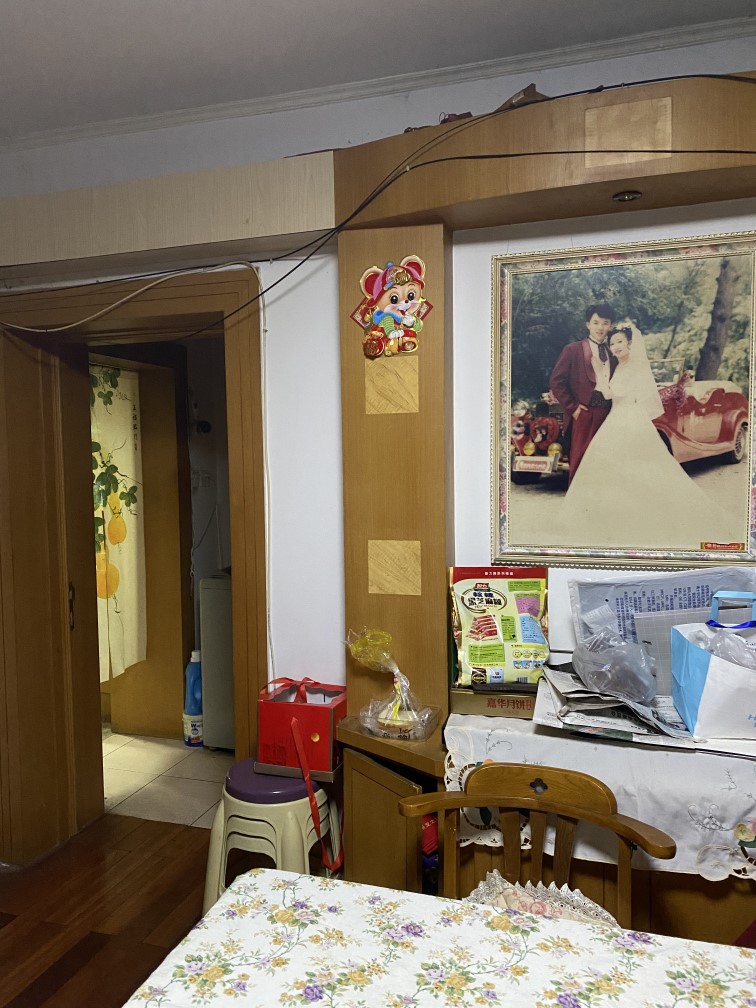
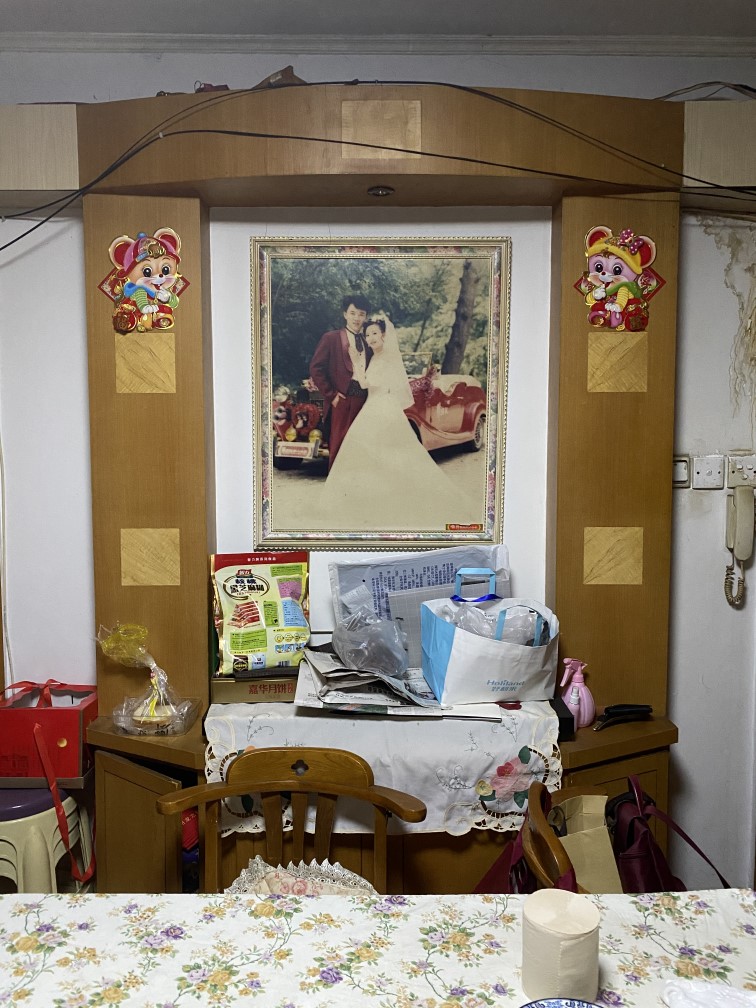
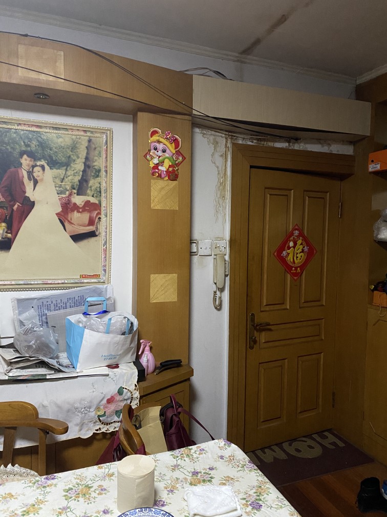
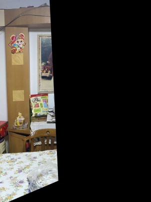
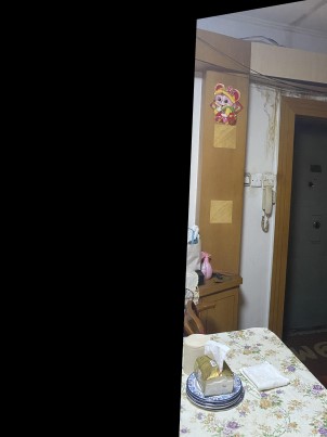
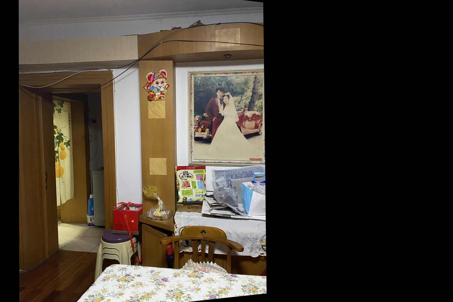
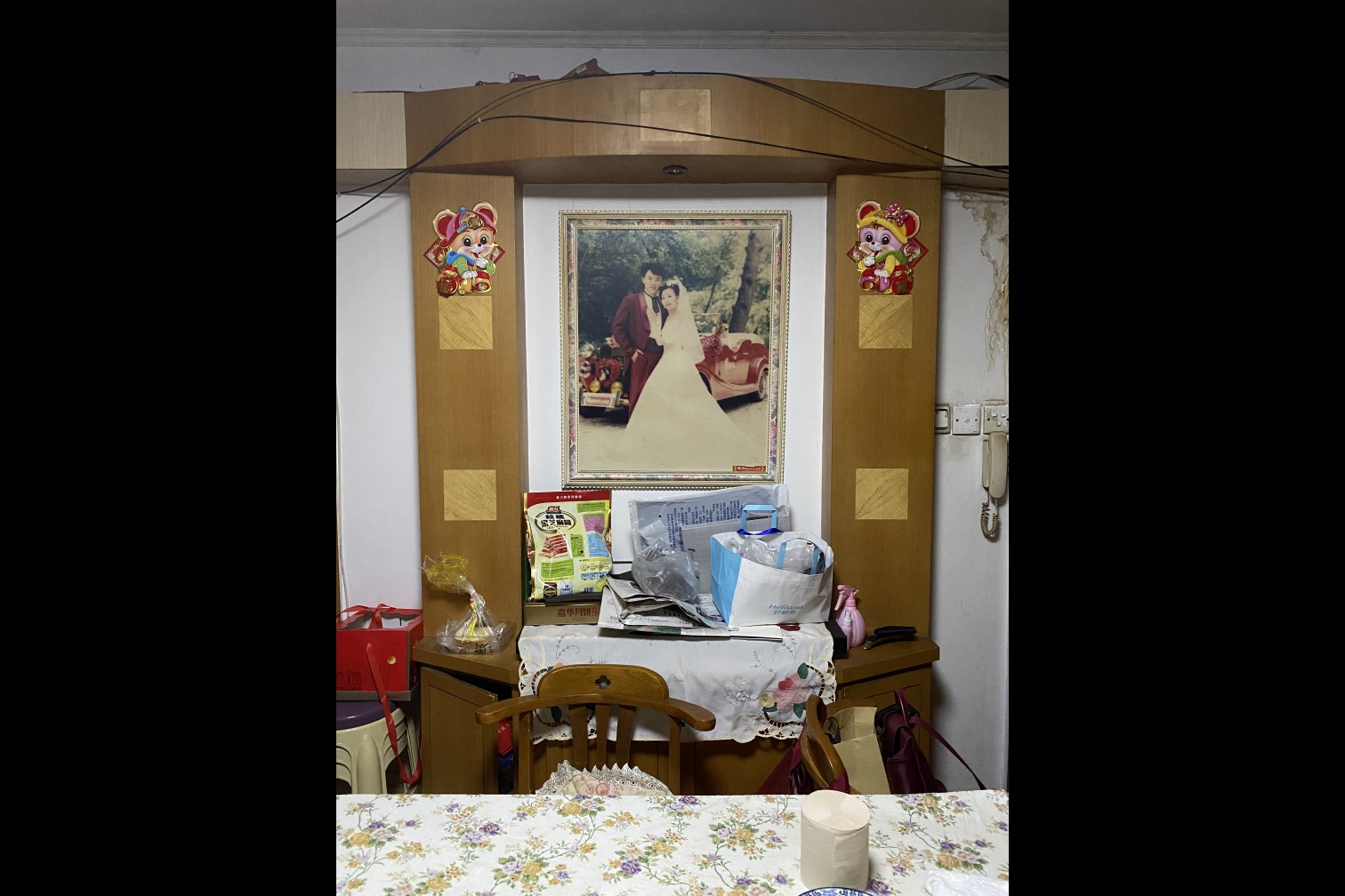
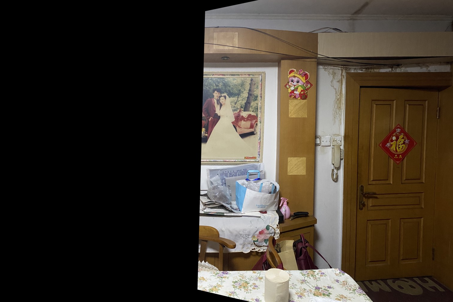
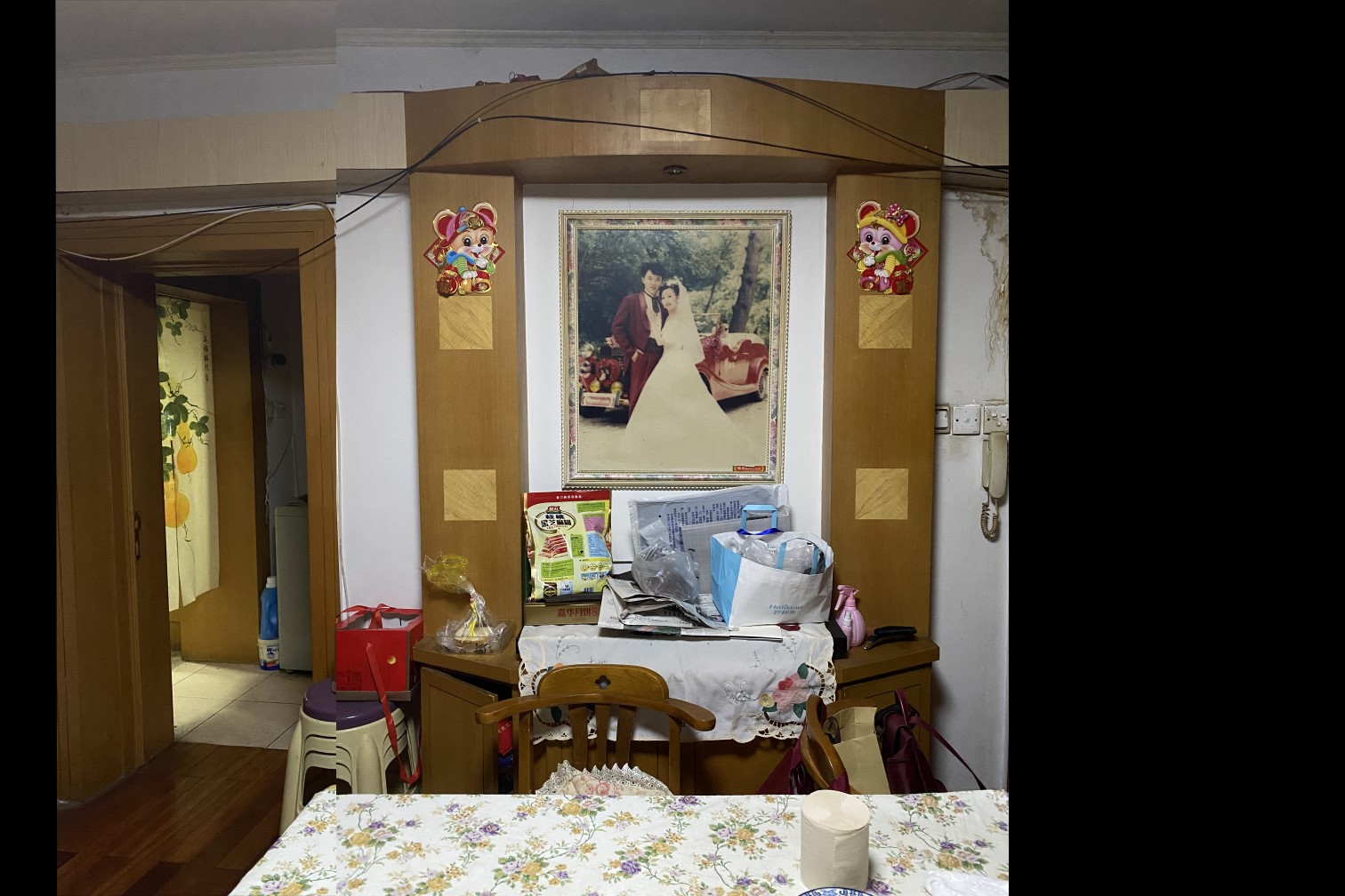
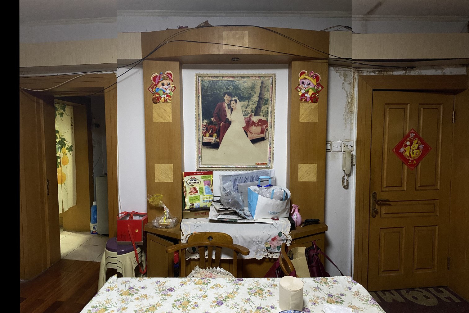
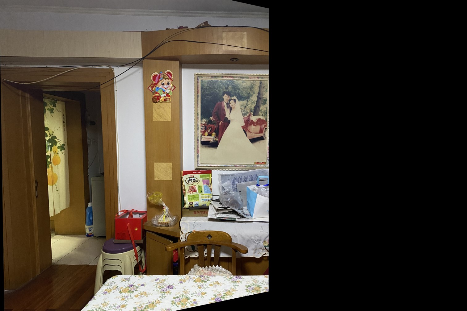
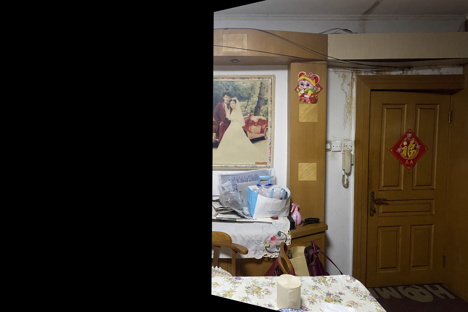
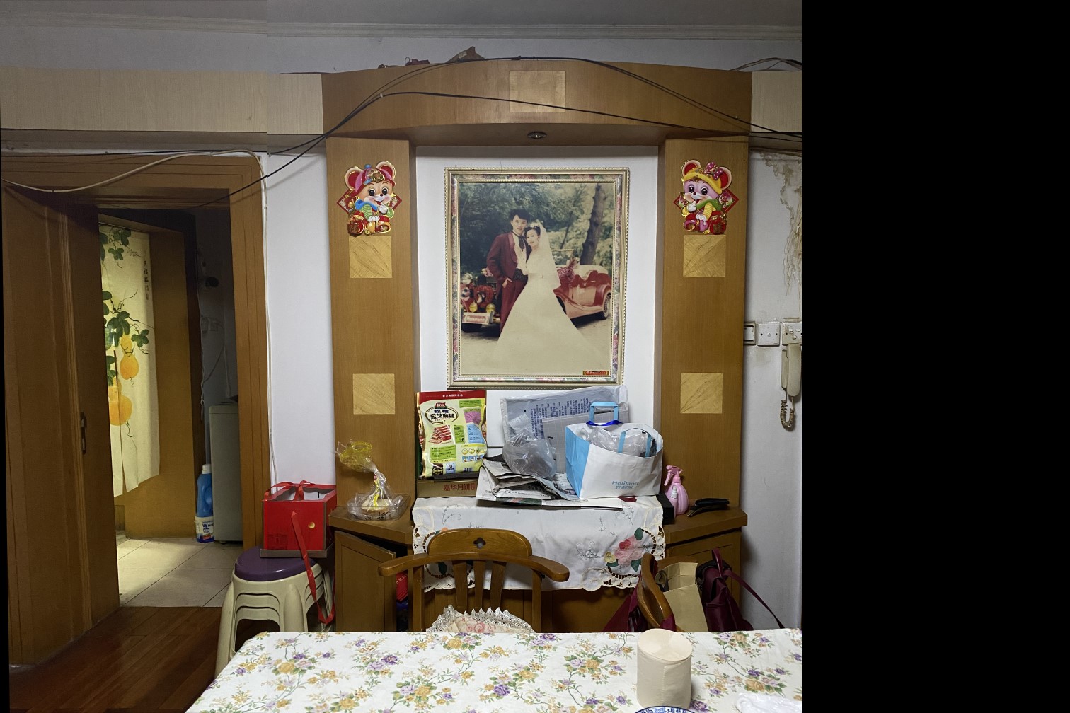
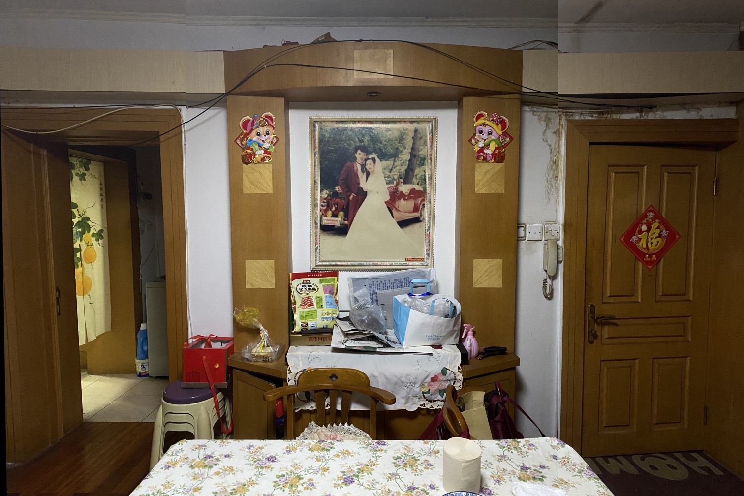
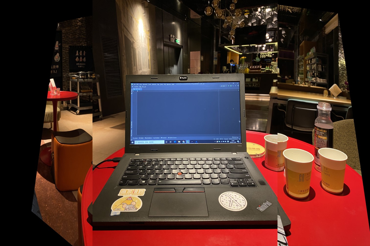
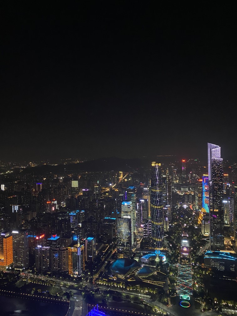
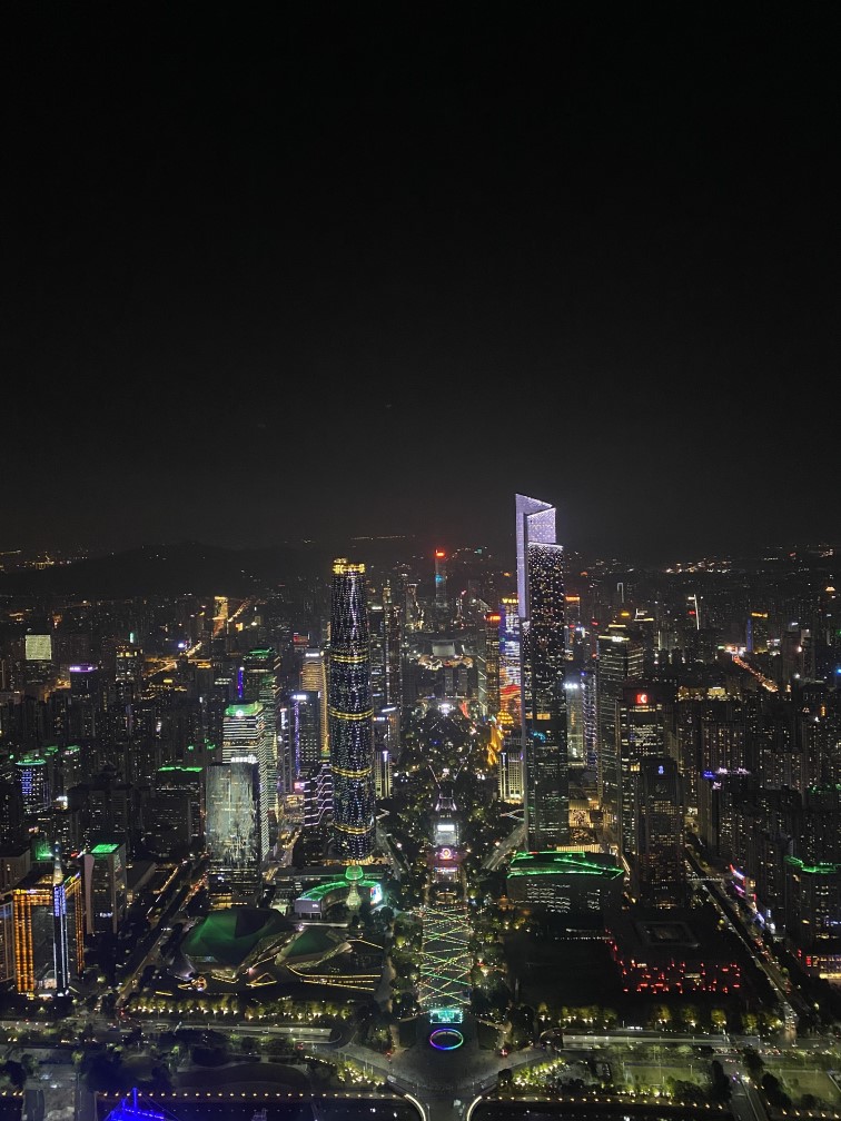
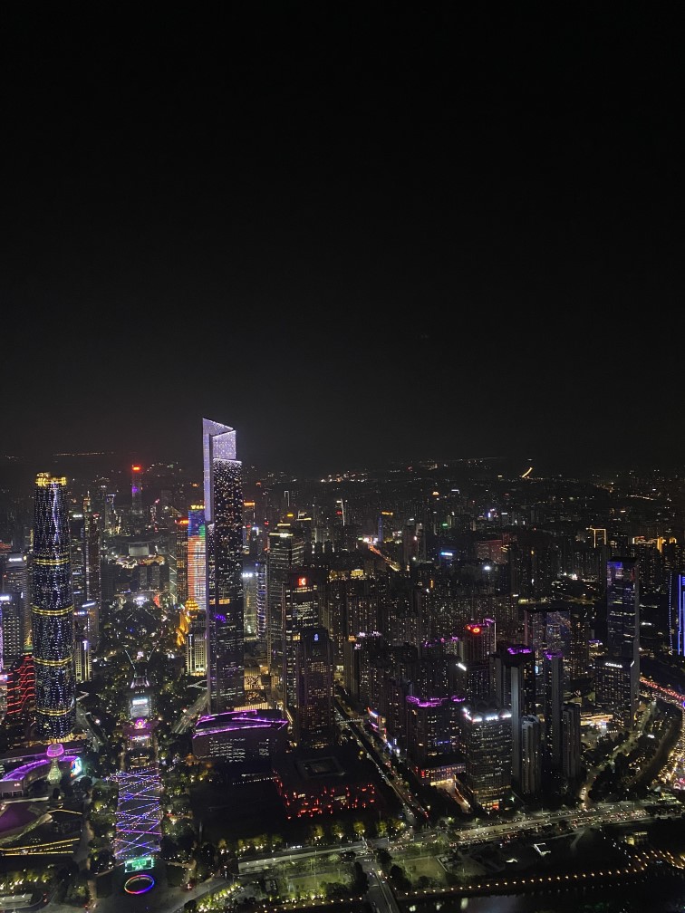
In this part, I took photos of my living room with a digital camera, where I stand in the center of the room and took picture with different view direction. I shoot pictures from the same position by turning camera instead of translating it. My original pictures are shown as follows:
In this part, I constructed a matrix from two n-by-2 matrices holding the (x,y) locations of n point correspondences from the two images in order to solve the linear system to get the recovered 3*3 homography matrix. Here, I used the least square algorithm to solve for the homography matrix.
When selecting the keypoints, I used the second picture as my target picture and used the computeH function to get the homography matrix for transforming the other two pictures into the second one. I chose the second picture because it is the "front view" of my room, which is ideal for serving as a reference. When selecting the key points, I used ginput function to select the square blocks in the images so that they can correspond to each other.
In this part, I used inverse warp to warp the images with the homography matrix calculated above.To test my functionality and the homography matrix, I first tried to warp several images. The following examples show how my initial warp algorithm works. In this example, I tried to wrap the wooden pillar in the side images to the same position as they are in the middle image. As we can see, even though the transforming leaves many pixels as "black", it still correctly warped the images into very close position as my target picture.
To further test my functionality and the homography matrix, I tried to rectify the images. In the example below, I took a side view picture of my ipad on my desk. Thereafter, I manually selected the four corners of my ipad, and defined its target by hand to be a square. The way I define the target coordinates is as follows:
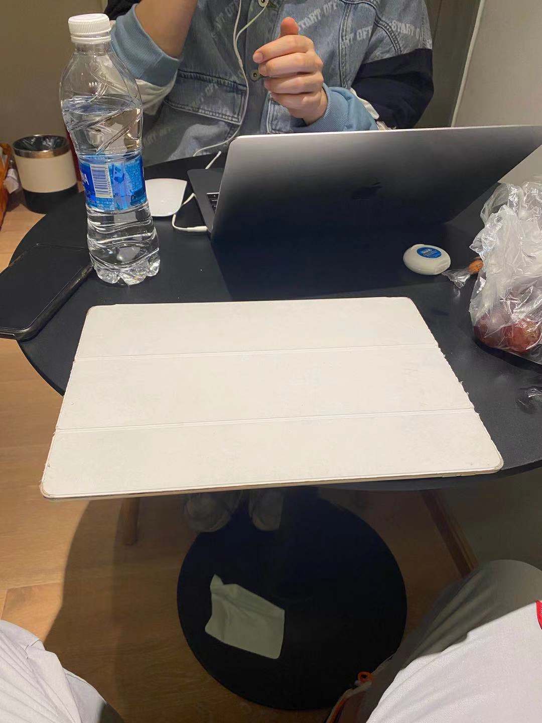
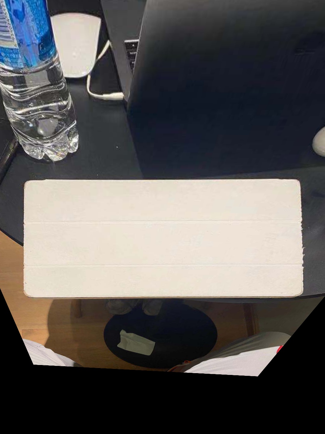
As we can see, it still correctly rectify my ipad through warping.
In order to bind the images into a mosaic, I used weighted averaging. To do so, I decide to use what I did in the previous part that I left the second image unwrapped and warp the other two images into its project. When deciding the final size, since all my original pictures are of the same size, I choose to keep the original picture's height and increase the width by 2 times (so that I can bind the other two images into one).
My final warpped images are shown as follows:
Thereafter, they are of the same shape and I can direclty stack them and get the final mosaic image. During the blending process, I used the technique from project two, where I used gaussian filter layers with Laplacian stacks and Gaussian stacks so that the images can be blended with respect to the points and the edge area can be smoothened to have better result. I blend the images one by one and the blending process is shown as follows:
In this part, I learnt how to use corresponding coordinates to bind images together and make a mosaic. More importantly, I started to understand how to use the knowledge we learnt before and how to apply the concepts into different cases. Also, in this part where I manually selected the points for warping and blending, I learnt how tedious and buggy this task is. First, the process of clicking on the images again and again is repetitive. In addition, if one select the points a bit off, the warping result can be very unpleasing. Even with techniques such as SSD or normalized-correlation matching patches, the result still may vary a lot and is not stable. Therefore, it is very necessary to develop an automatic detecting algorithm that is faster, stabler, and more precise.
This part, will we follow the instruction in the paper "Multi-Image Matching using Multi-Scale Oriented Patches" by Brown et al with several simplifications. The purpose of this part is to automatically generate the homography matrix that can best match two or more images so that they can be blended together more precisely.
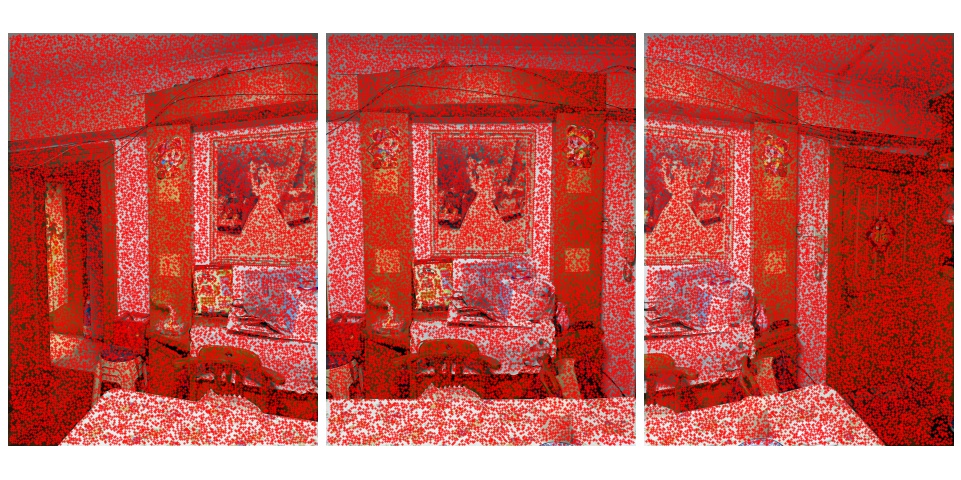
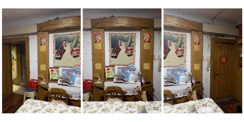
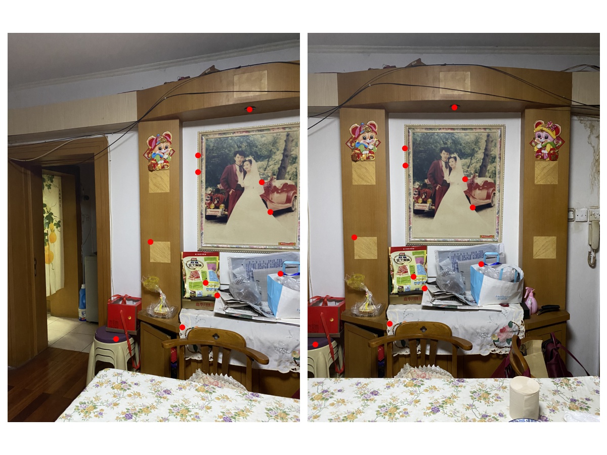
In this section, I utilized the provided skeleton code to find the harris corner with several improvements. With the original provided code, the detector found too many corners that it is not distinguishable on the plot and is hard to proceed with matching algorithms. Therefore, I changed the min_distance argument to a better value so that the number of corner detected is reasonable and the corners are representative enough. Also, the original code uses peak_local_max for identifying corners, which makes the corners spread across the whole image. I designed a new input for this function that can change the function from using peak_local_max to using corner_peaks, which turns out to detect corners on the "edge" areas of the image. The results are shown as follows:
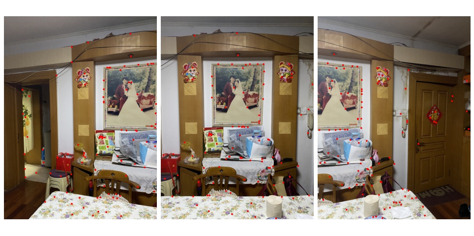
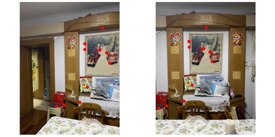
In this section, I implemented the Adaptive Non-Maximal Suppression so that only the most representative corners are preserved, which can thus reduce calculation complexity. The corners are chosen based on the corner strength, and only those that are a maximum in a neighbourhood of radius r pixels are retained. The purpose of this algorithm is to restrict the number of corners to a desired value. In the following examples, I restricted the number of intereting point to different number with Adaptive Non-Maximal Suppression under different point detector.


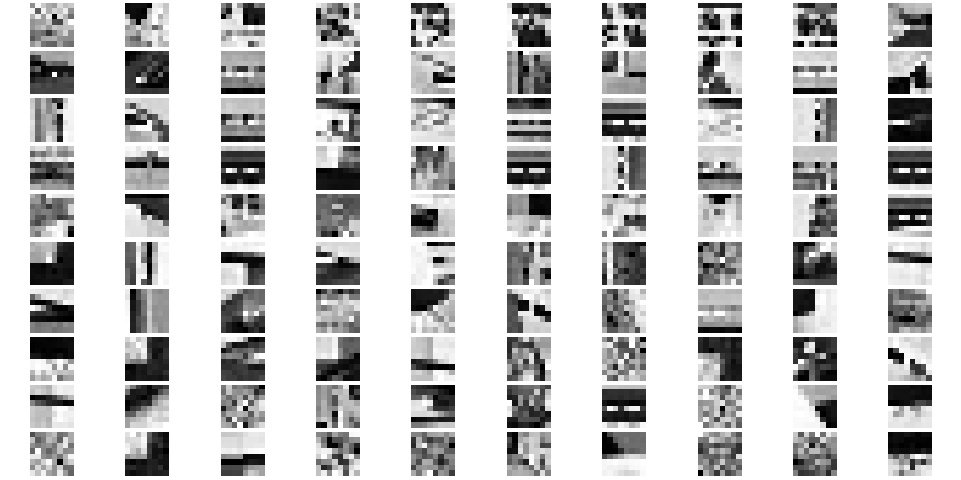
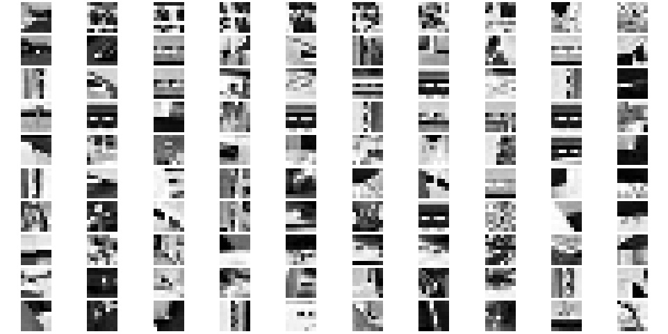
In order to find the best matches later on, we try to find a feature descriptor for each interesting corner detected in this section. The way I find the feature descriptors is through filtering and downsampling. I first smoothed the image with gaussian filter to blur the image. Thereafter, at each interesting corner, I find a 40 by 40 pixel patch around that corner and downsample the batch to size 8 by 8. And use these 64 values as the feature vector of that corner. Some examples are as follows:
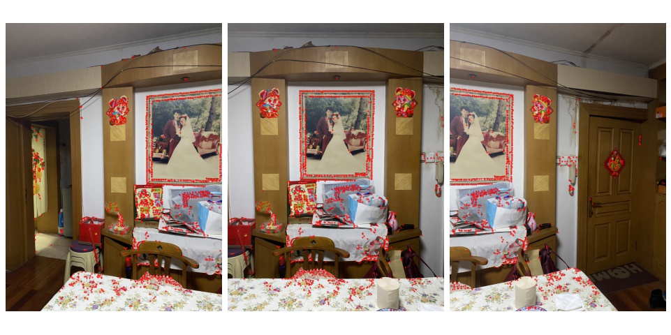
Once we have the feature vectors of each corners above, we can start to find the best matched corners that can be used for finding the homography matrix and make the mosaic image. I used approach due to Lowe of thresholding on the ratio between the first and the second nearest neighbors and chose the threshold to be the value in figure 6b that result in most correct matches. However, there is some special cases where the threshold in figure 6b provide less than 4 points as required by our RANSAC later. Therefore, when the matched points selected are less than some number (10 in my case), I will increase the threshold and calculate it again until I have enough points. The matched interesting corners are shown as follows:
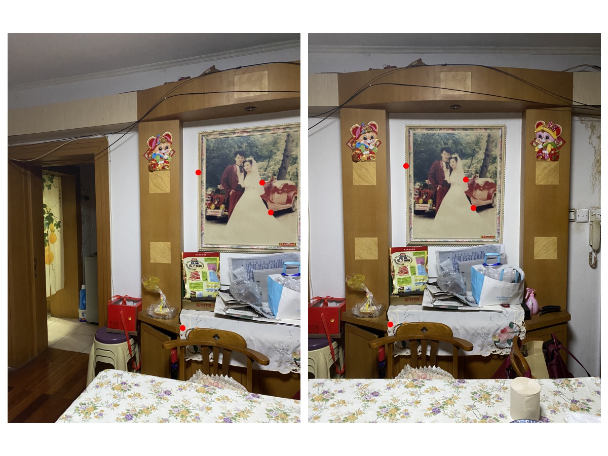
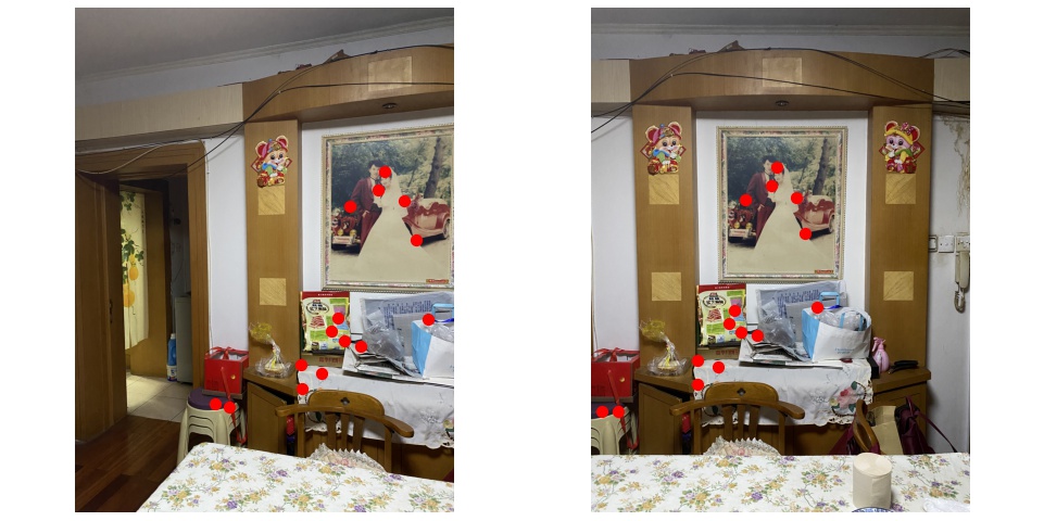
With the best matching corners, I implemented the 4-point RANSAC algorithm to find the best points that should be used to calculate the homography matrix. With large number of iteration and randomness when choosing the points, the algorithm tries to find the homography matrix that can result in the largest set of inliers. My final results are shown as follows:
As we can see, this algorithm provide much more reliable matching than the one with manual operations. Several other comparisons are shown as follows:
In this part, I learnt a lot on how to automatically choose interesting points in order to find correct and best matching pairs to calculate for homography matrix. With comparisons above, it is very clear that the RANSAC produced mosaic image is much better than the one produced by manual operations. The coolest thing I learnt from this project is how we suppress the number of interesting points from exceedingly lot to reasonable to best matches. Especially when the algorithm find matching points that I did not even notice, I find it so cool!
In my code for corner detection and feature description, I improved the original code to support mutilscale processing. Both functions now can take three-channel colored picture as input. Example colored features are shown as follows: