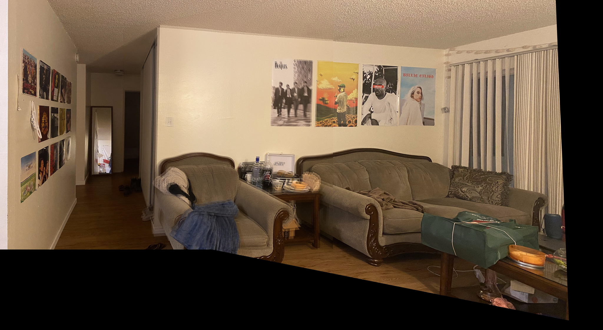
In this project, I take pictures and perform homographies on them to warp them. These projective transformations allow me to accomplish rectification and morphing of images into a mosaic.
For the next part of the project, we wanted to be able to automate the image annotation. In the above procedure, we had to manually input the correspondence points for each image to aid in the stiching of the two images. In this part, we create a system that will automatically determine the correspondences and stitch them together to form a panorama image. Many of the parts in this project are inspired by this research paper by Brown et al.
After taking photos from the same point of view, I want to transform the images into the right shape so
that they could be stitched seamlessly together. In other words, given an point (x,y) in image 1,
we want to find its corresponding point in image 2 (x',y').
| |
To find the matrix H, we need find a series of correspondences such that a point (x,y)
in image 1 corresponds to a point (x',y') in image 2. Once we have the correspondances,
we can set up the system of equations below for each correspondance to find the values of H.
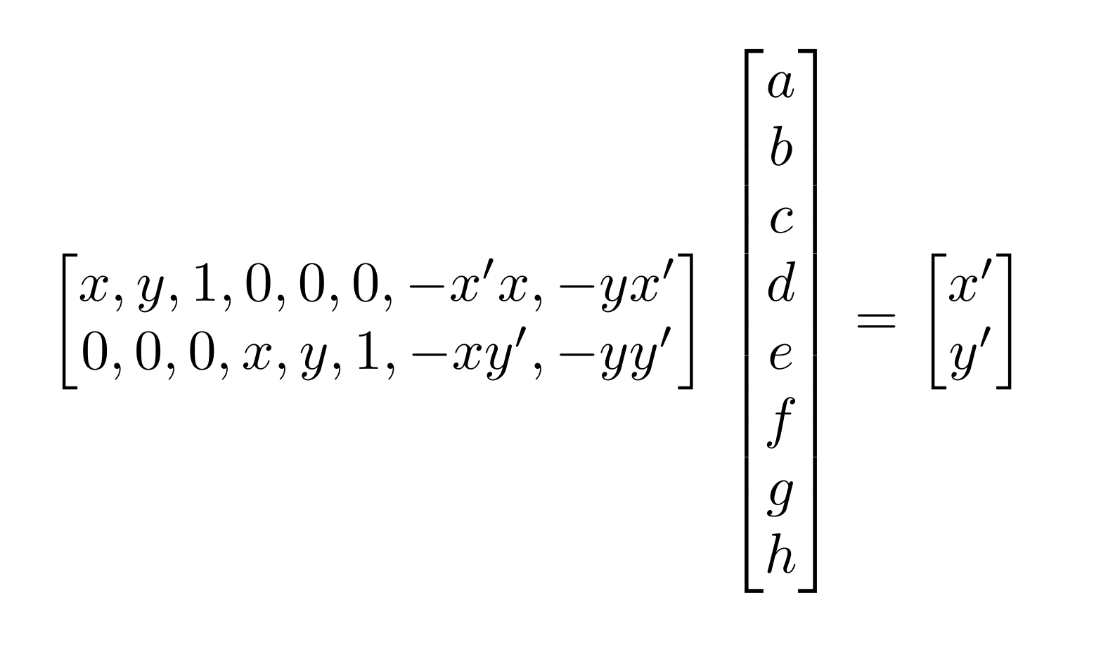 |
We would only need 4 points to give us to determine matrix H, since there are 8 degrees of freedom. However, in my solution, I offer more points to create an overdetermined system to solve for the homography matrix in order to decrease the effect of noise. To solve an overdetermined system, we solve for the matrix with the least squared error.
With the idea of homography, I can now transform the image into any shape within the scope of perspective transformation. With a homography matrix, I can now map every pixel from one image to be seen from the perspective of the other image. This gives opportunity to use warping to rectify images. For example, if we have an image that is taken slanted or from a side angle, I can rectify it finding the transformation matrix that takes the four corners of the a square in the image into a square coordinates.
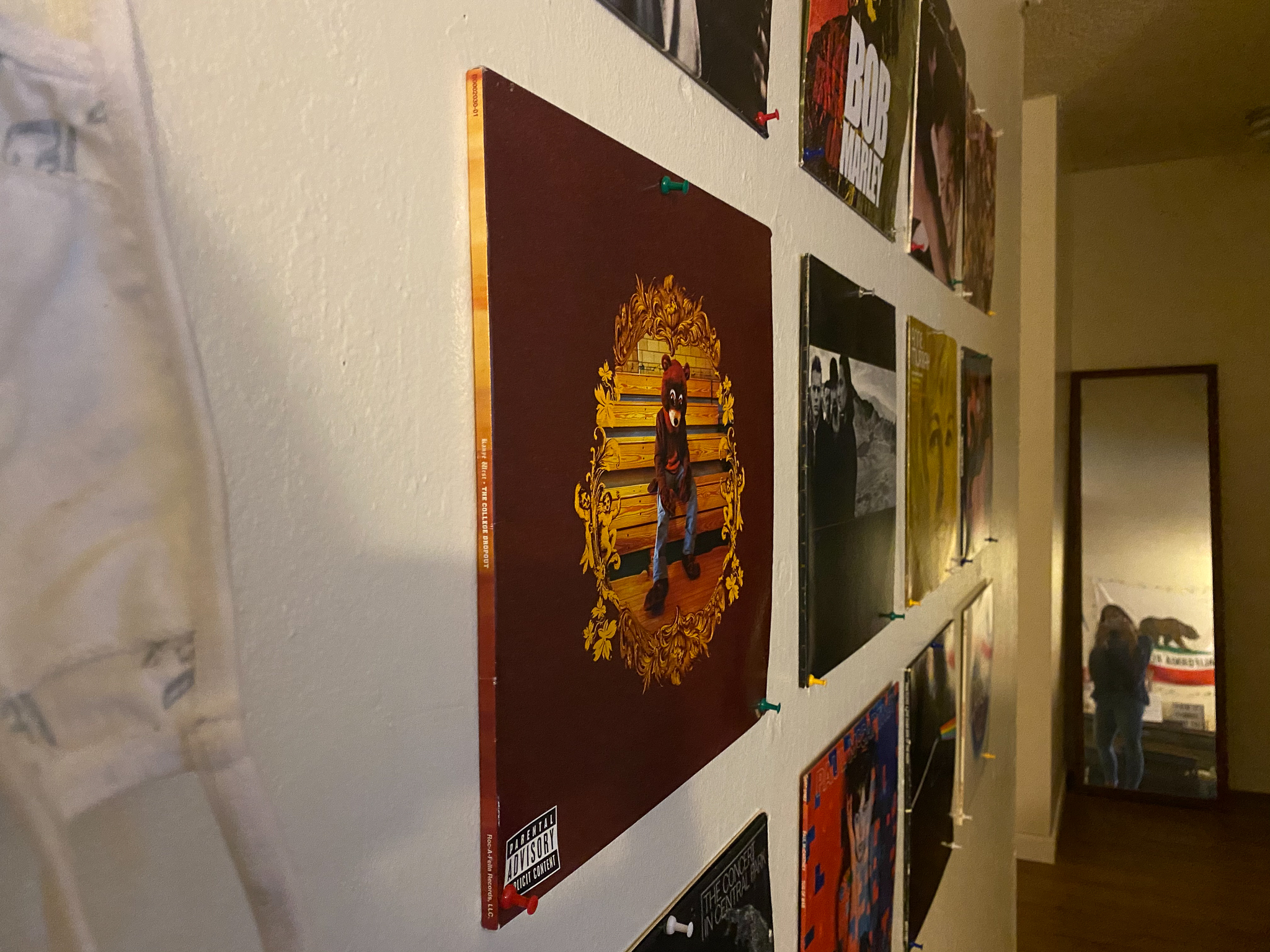
Here is an example of rectifying an album cover from a photo of my wall taken from a side perspective:
|

|
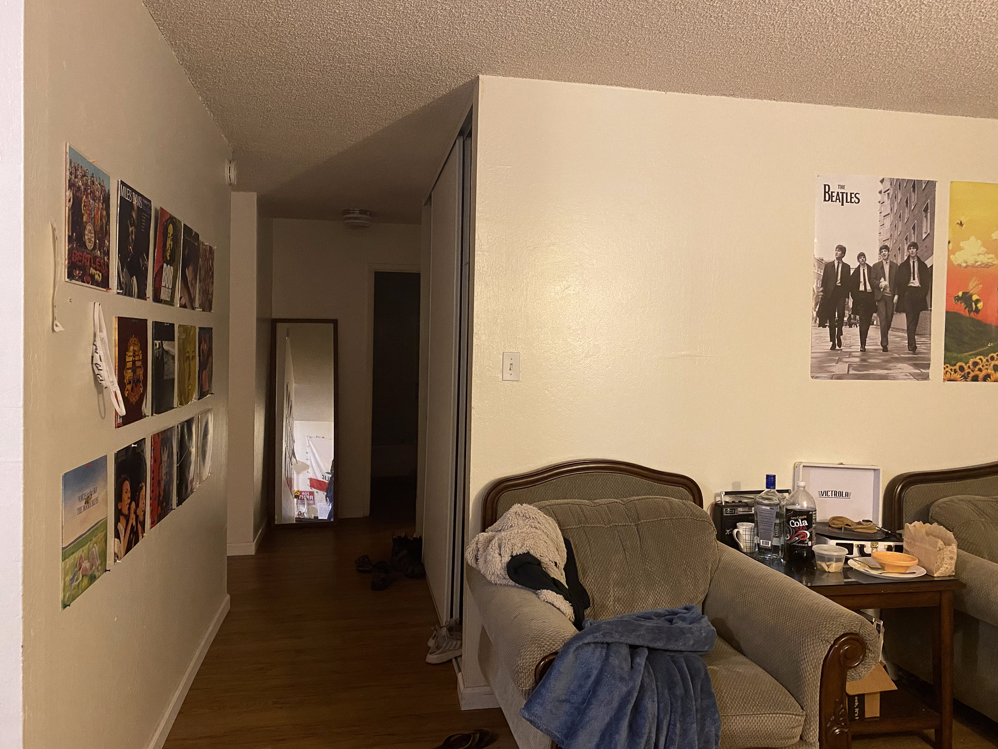
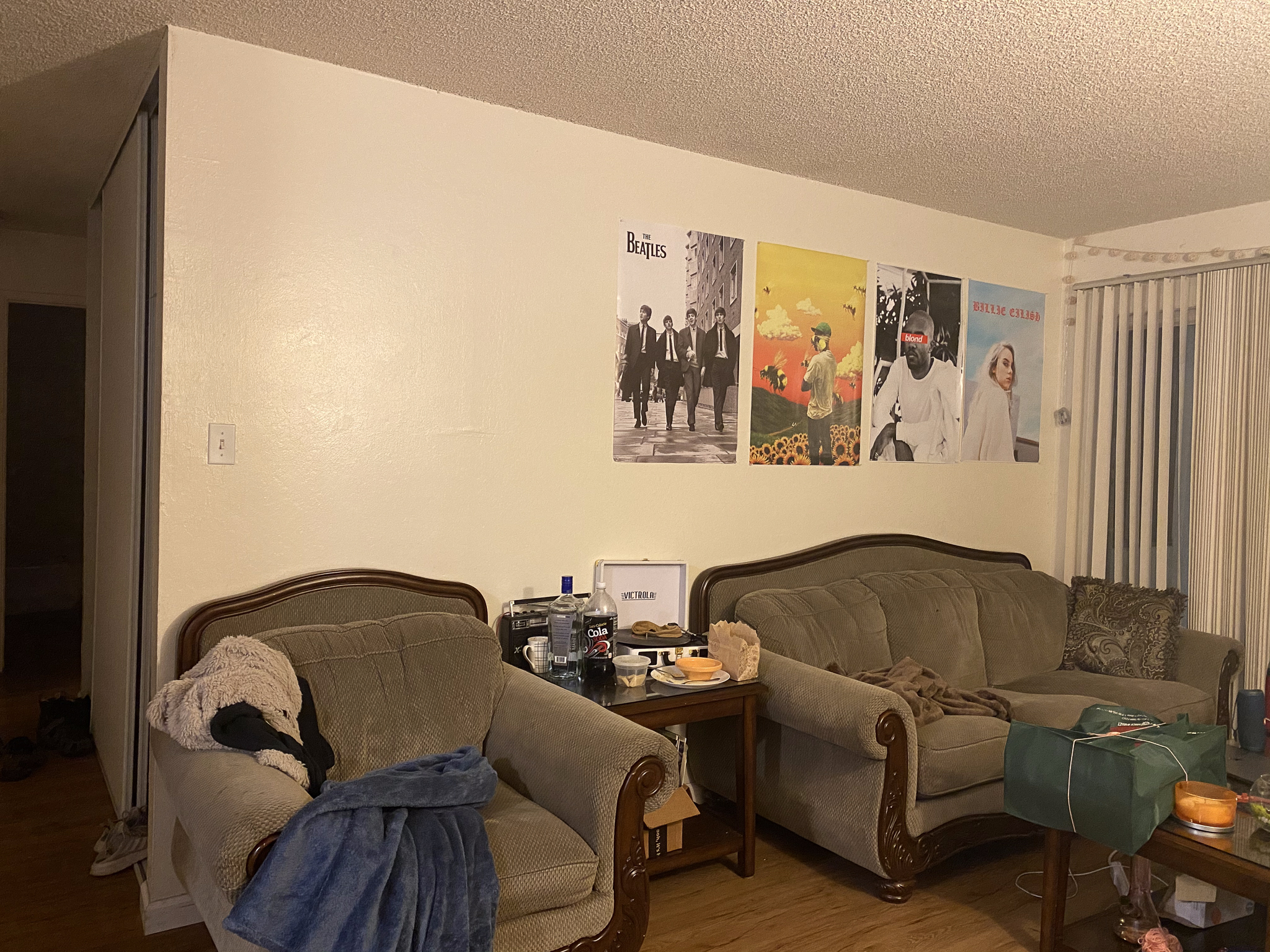
Above, we showed how we can warp shapes in an image to say a square. Now, we want to attempt warping image shapes to match with the images we want to stitch together into a mosaic. We can do this by choosing correspondence points between two images that correspond to the same points. For example, in the images below, I can use the corners of the Beatles poster to match coordinates and perspectives in the two images:
|
|
Then, using these correspondence points, we can determine the homography matrix and warp one image so it mimics that perspective of the other image and the two images can then we overlayed on each other. Finally, stitching together these images can produce a panorama image.
 |
The beginning of this project gave me incredible insight on how features like panoromic imaging works on our phones. One thing I was surprised by is how much information is actually encoded in images. This became clear in the rectifying exercise. I was surprised the album cover could be so perfect recreated, even when it was hard to visually see the cover art in the image.
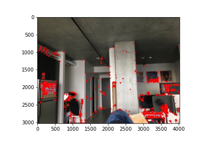
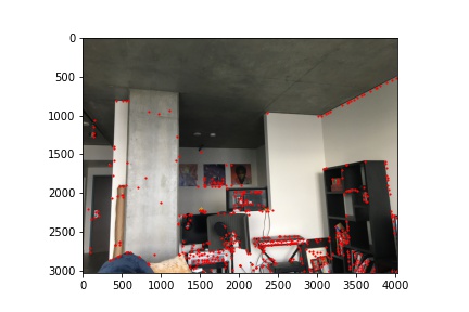
When choosing point correspondences between images, we want to choose good features that are prominent and easy to localize. Good features that satisfy these properties are corners. In order to detect corners in images from scratch, we use a Harris Interest Point Detector to find these corners in out images automatically. The results of the detector on sample images are shown below:
|
|
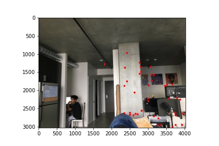
Harris Interest Corner Detector's output can range up to the thousands. As you can see in the above images many of the detected corner points are around the same corner and are condensed. To reduce the number of corner points we have, we want to build a Adaptive Non-Maximal Suppression (ANMS) filter on the detected corner points to get a more evenly distribution of the points in the images. ANMS will calculate the minimum suppression radius r for each point.
 |
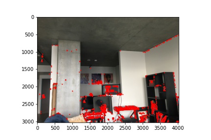
We can specify the number of corner points we are interested in. After implementing this filter, we can significantly reduce the number of corner points we can use for our correspondences:
|
|
Now with a more managable set of points, we can begin the process to match correspondence points across images. In order to this, we need to compare the patches around the corner points in the left image with the right image to match correspondence points. To do this, I took a 40x40 patch around every corner point identified by ANMS and then downsized this patch to an 8x8 patch, normalized this patch, and then shaped this patch into a vector so it can easily be compared with other patches. Below are examples of the downsized patches around the identified corner points:

|

|

|
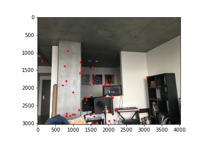
With these descriptors, for every corner point in the left image, I compared its 8x8 patch with every 8x8 patch in the second image. By comparing the patches using the sum of squared differences, I found pairs of patches that best matched. We also determined a threshold to reject outliers in our matches. After this, we were left with correspondence corners across both images:
|
|
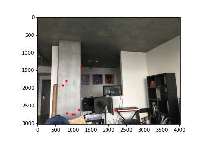
You may notice in the image above, there are correspondences sets that are bad. To robustly remove bad matches in our current set of correspondences, we will use random sample consensus (RANSAC). To do this, we will randomly sample 4 different point correspondences from our images, compute the homography transformation between them, and see whether the homography aligns with the other correspondence points we identified. We keep the correspondence points that satisify a certain threshold of satisifying the other correspondence points. This again reduces the amount of the correspondence points we have:

|
|
Finally, we can use these correspondence points as we did in part A to stitch together the images to form a panoromic view.
|
|
|
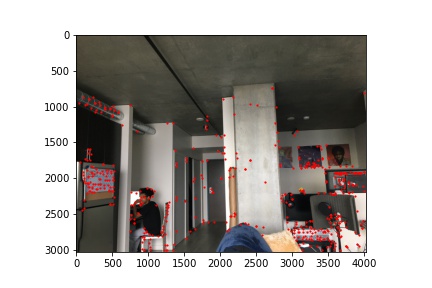
I ran this automated system on my orginal sample images used in part A to see how they compare. As you can see in the images below, automating the corner detection is fairly comparable to the results from manually entering correspondence points:

|
|
I learned a lot of various techniques in this project that did not rely on prior training data to get incredible results. This is what I found to be most impressive. Often we associate computer vision techniques with ML techniques; however, in this project, we see the power linear algebra alone can bring into computational photography.