Part A: Image Warping and Mosaicing
Overview
In this project, I am using various computation photography techniques as discussed in lecture in order to stitch together two images of the same scene but taken from different angles. The first part of this project involves computing the homography matrix based off of two sets of correspondence points, warping the images and doing image rectification, and finally blending the images into a mosaic.
Part 1: Shoot the Pictures
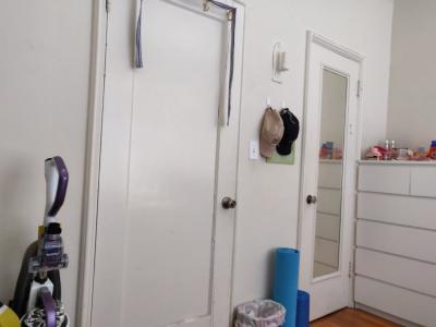
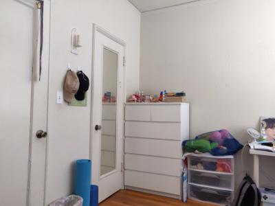
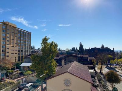
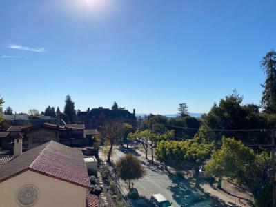
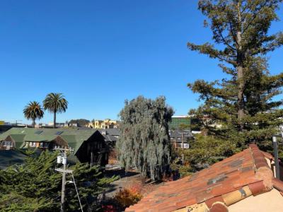
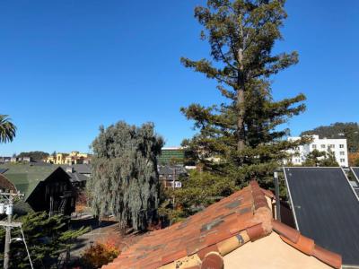
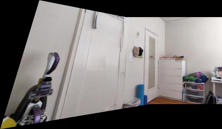
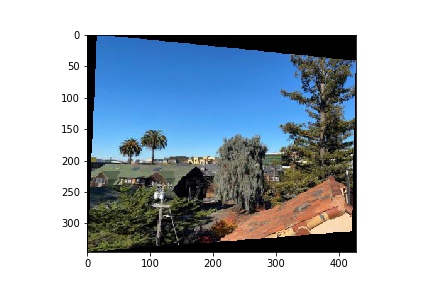
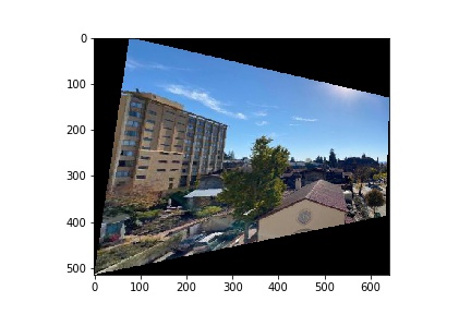
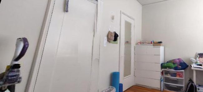
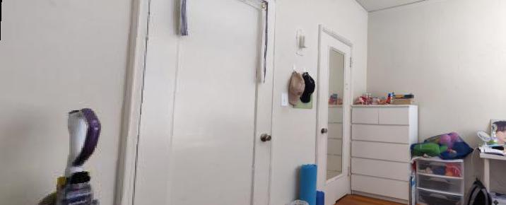
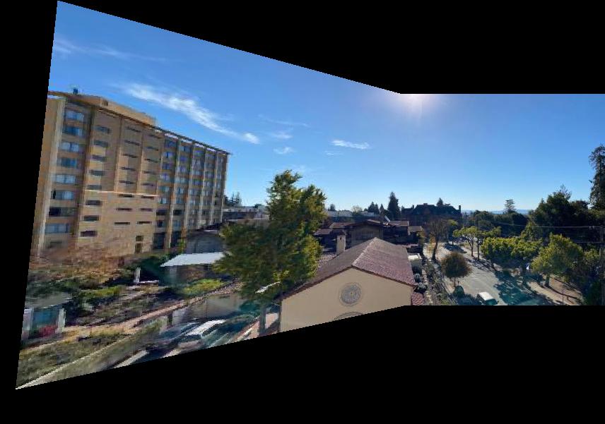
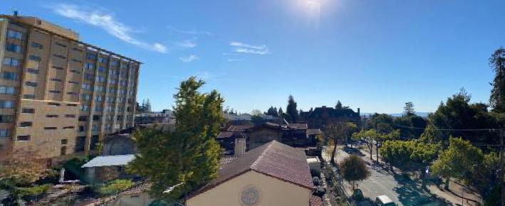
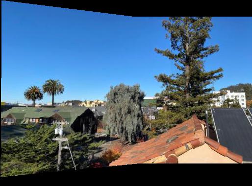
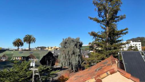
Since it is in the middle of the COVID-19 pandemic, I have opted to take pictures of and outside my Berkeley apartment instead of various exciting outdoor locations. As described in the spec, I used the AE/AF lock to ensure that my camera settings stayed stagnant between shots, as well as made sure that there was a decent amount of overlap between the pictures. Here are some example pictures below:
|
|
|
|
|
|
Part 2: Recover Homographies
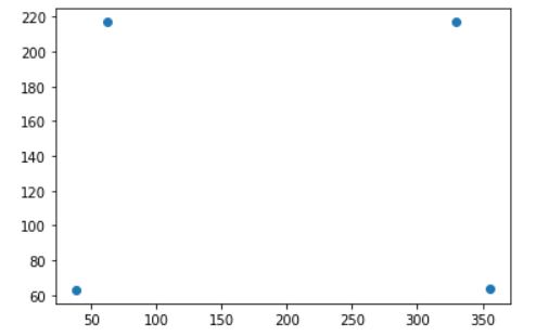
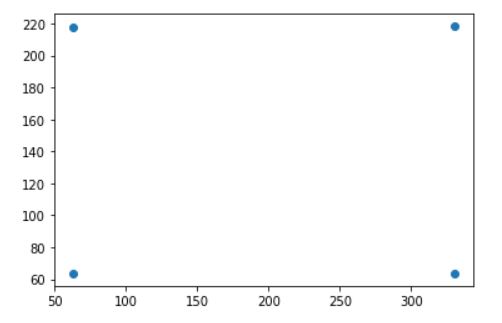
I then wrote the computeH function to construct the homography from two sets of correspondence points. I used Stack Overflow to get the correct rows for my matrix A, which has two rows corresponding to each pair of correspondence points, for a size of 8 x 8 for 4 correspondence points (2*n x 2*n for n correspondence points). I also constructed the vector b from the second set of correspondence points, for a size of 8 x 1 (or 2*n x 1). I then did least squares on A and b to solve for our homography matrix H (reshaped to 3 x 3).
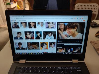
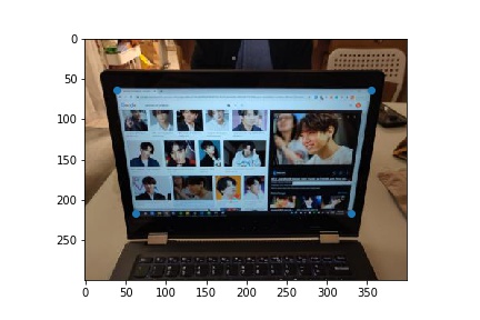
I tested my computeH function using correspondence points on a picture of my laptop.
|
|
|
|
|
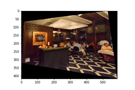
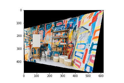
Part 3: Warp the Images / Part 4: Image Rectification
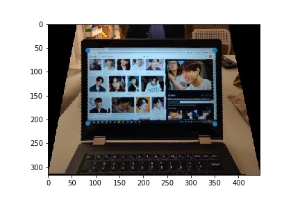
My approach is similar to the methods that we used in Project 3 to warp from one person's face to another. Except here, we are only warping one shape, rather than a triangle mesh. Another point of difference is that I decided to use forward warping instead of inverse warping. I use a mask defined by the warped bounding box of the original image as my base image. I then call polygon() on these warped corners and use the raw pixel values from the corresponding points in the original image to fill my base mask. I ran into some difficulty here with my warp cutting out the portion of the warped image on the left; however, I solved this by adding an offset into the polygon function and subtracting it from the result, as a way of normalizing the indices returned by the function. You can see the results of my warping function on the image rectification examples below.
|
|
|
|
|
|
To achieve the image rectification, I selected correspondence points on the shape in the image that I wanted to warp and guesstimated the rectified shape. For the laptop, this was the monitor. By applying my warp function on the original image and these correspondence points, I was able to achieve the result above.
Part 5: Mosaic
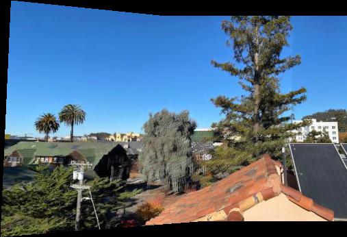
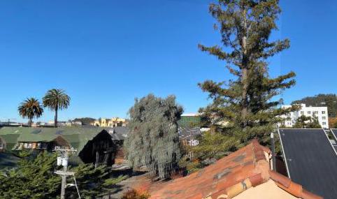
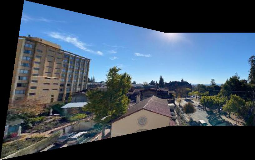
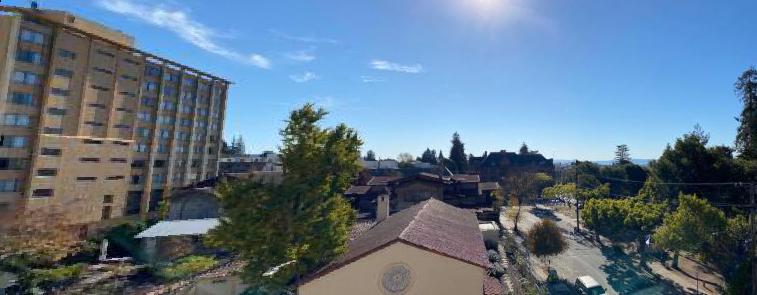
In order to align the warped image from the left and the original image on the right, I had to create two base masks. I determined that these masks should have the maximum dimensions of either image, in order to fit all of the points in the image. I then padded the right image with the offset from the warp so as to correctly align its features with the warped left. I then blended these two masks together onto one resulting canvas. I found the np.maximum function very useful for this purpose, so as to take the higher brightness value in between the two images.
|
|
|
|
|
|
|
|
|
|
|
I will include these mosaics with manually selected correspodence points later on as well for the sake of comparison with the auto mosaic.
What I Learned
The most important thing I learned in this part to have patience and keep trying. I spent a lot of time trying to get the warp exactly correct. First there was problem with my homography matrix, then I didn't understand how to use interpolation for the forward warping, then my warp was mostly correct but would go out of bounds. After spending many hours fixing all of these issues, I was able to achieve a satisfactory result, with a strong understanding of how the project works.
Part B: Feature Matching for Autostitching
Overview
In this part of the project, I am expanding on the previous image mosaicing by creating a program to automatically detect feature points shared between images. This improves upon the results achieved in the previous part of the project, as manally selected correspodence points are not ideal. This project is inspired by the paper "Multi-Image Matching using Multi-Scale Oriented Patches” by Brown et al and follows the process outlined in Sections 2 through 5. The specific steps involved in the auto-stitching process are first detecting corners in the image, extract feature descriptors for those points, matching the descriptors between images, and finally applying RANSAC to compute the ideal homography matrix. From there, the warping, aligning, and blending of the images is same, except with an improved, smoother, and more accurate mosaic.
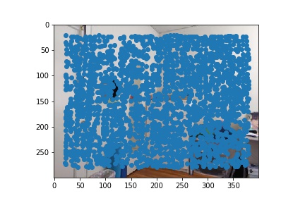
Part 1: Detecting corner features in an image
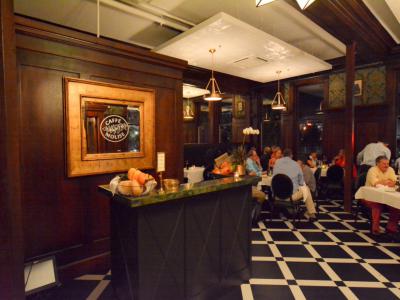
For this step, I used the sample code for the Harris Interest Point Detector as linked in the spec. I made one minor adjustment to use corner_peaks as per the advice of Piazza, so as to produce a less overwhelming amount of points. As you can see, the Harris detector alone gives a very large amount of points, but the keypoints around the mirror, door, and drawers are concentrated which is an indicator of the pixel value changing sharply around that area.
|
|
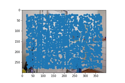
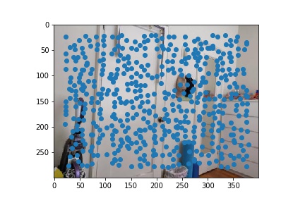
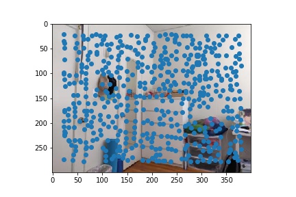
To narrow down the potential points and guarantee a relatively even distribution, I implemented Adaptive Non-Maximal Suppression (ANMS). In ANMS, we iterate through all of the points identified by the Harris detector, and we calculate the minimum suppression radius r. I decided to keep the 500 points with the largest radius. The results after applying ANMS are below.
|
|
Part 2: Feature Descriptor Extractions
For this step, I iterated over all of the ANMS points and evaluated a 40x40 patch around the corner point. I first put the patch through a 5x5 Gaussian filter then downsampled it to 8x8 and finally normalizing it before vectorizing it. The blurring helps reduce noise so that we are able to better extrapolate the feature matches. A
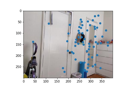
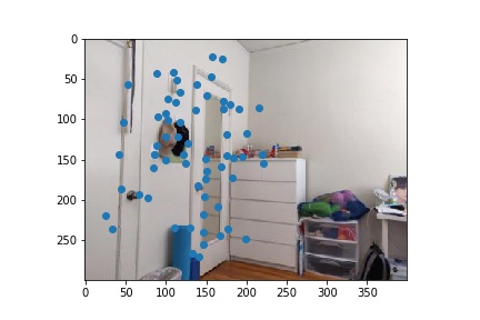
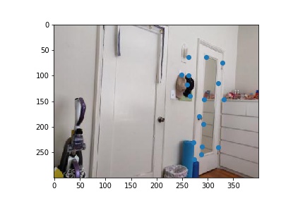
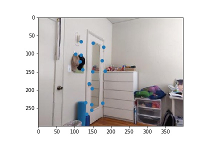
Part 3: Feature Matching
In order to match the features between images based off of the descriptors, I essentially applied nearest neighbor but with a threshold for including the nearest neighbor to a point. The idea behind this is that a correct match should be significantly better than all other potential matches. Based off of the paper, I chose my threshold ratio for the dist of the 1-nn / dist of 2-nn to be 0.3. Below are the results after feature matching.
|
|
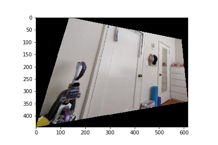
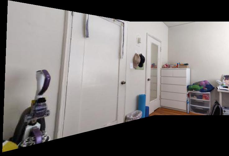
Part 4: RANSAC
I then used RANSAC to compute the a robust homography matrix estimate. The process is as follows: We first take 4 point sample from our matched pairs and compute the homography matrix H' from those pairs. Then we compute the inliers from p' = H' * p with the desired point from image 2. We repeat this process for some number of iterations (I chose 200), continually updating a running list of inliers to be the one with the maximum length. Finally, we compute the homography matrix H from those max inliers. After computing H, we warp and construct the mosaic as in Part A. Here are the results below, with comparisons of the final warp when manually vs automatically choosing points.
|
|
One can see a major improvement in the room mosaic when observing the door handles. Because I did not select the door knobs as one of the correspondence points for Part A, they got blended out. However, the auto-mosaic algorithm is more robust and we are able to get a very clear picture.
|
|
|
|
|
|
|
|
|
|
|
|
|
|
|
|
|
What I Learned
The most important thing I learned in this part was how to read a technical computer science paper and understand it enough to implement it myself. I was intimidated by the text at first, but later amazed at how much the authors were able to express in such small sections. It was a very rewarding experience to apply the same techniques in my code.