|

|
|
|

|
|
|
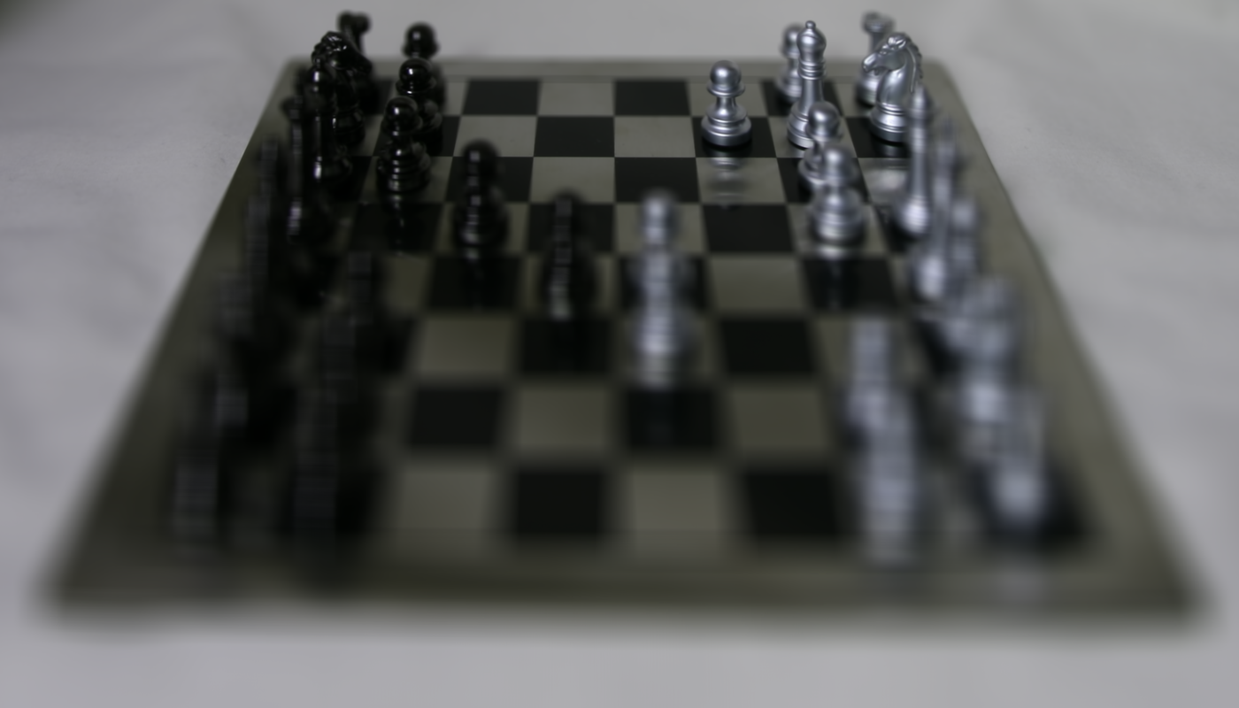
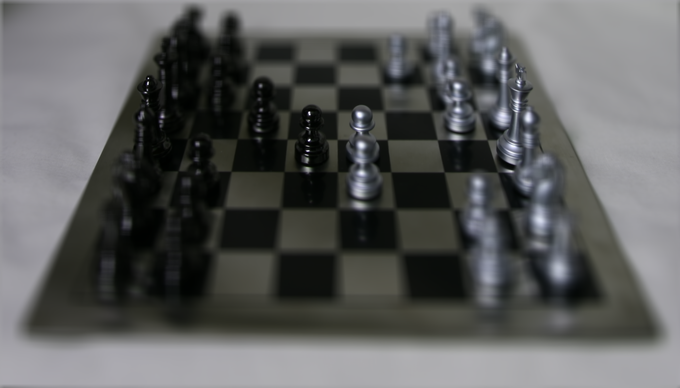
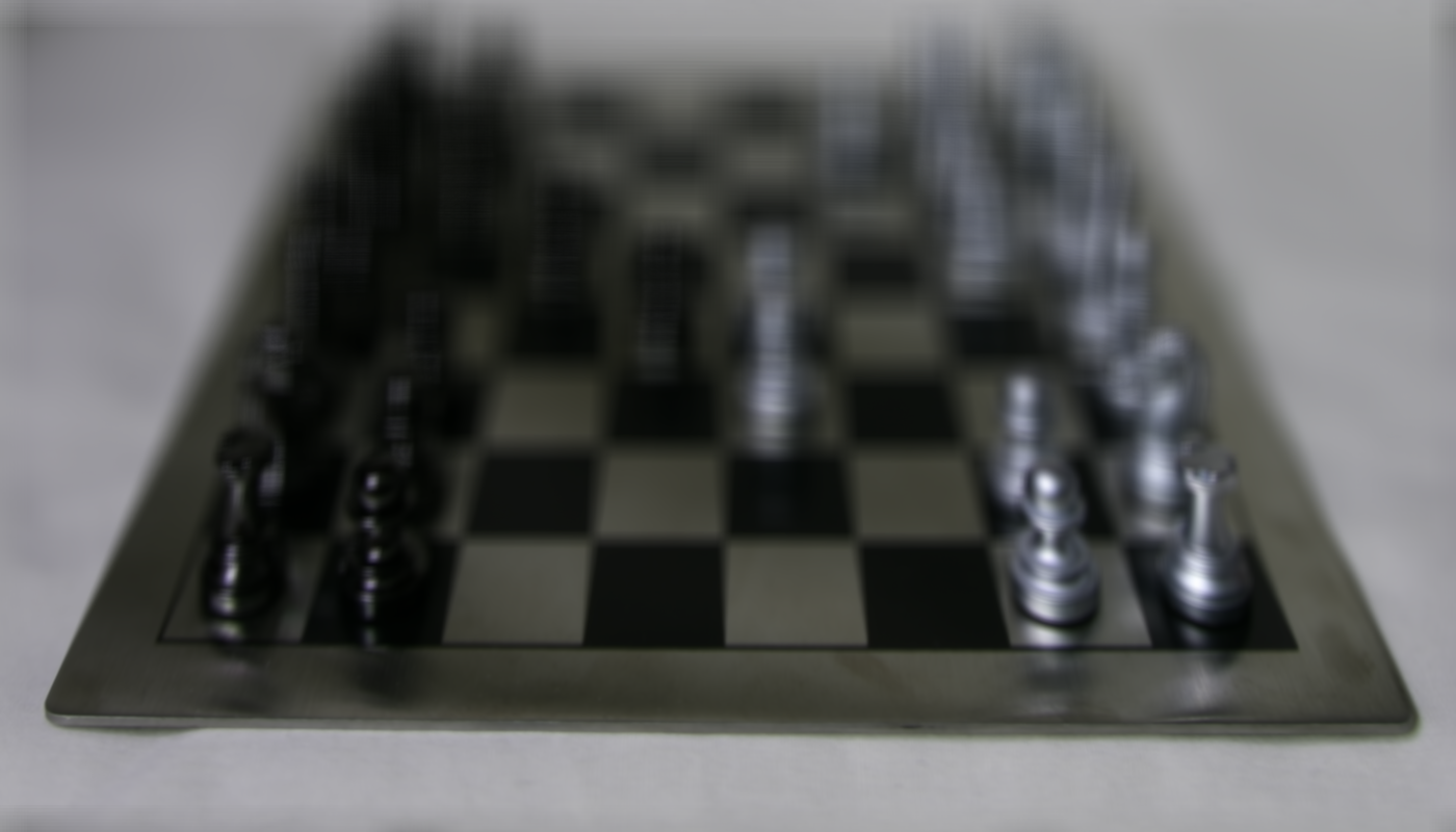
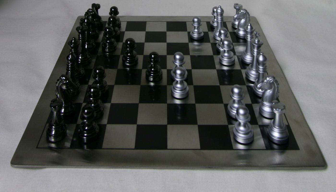
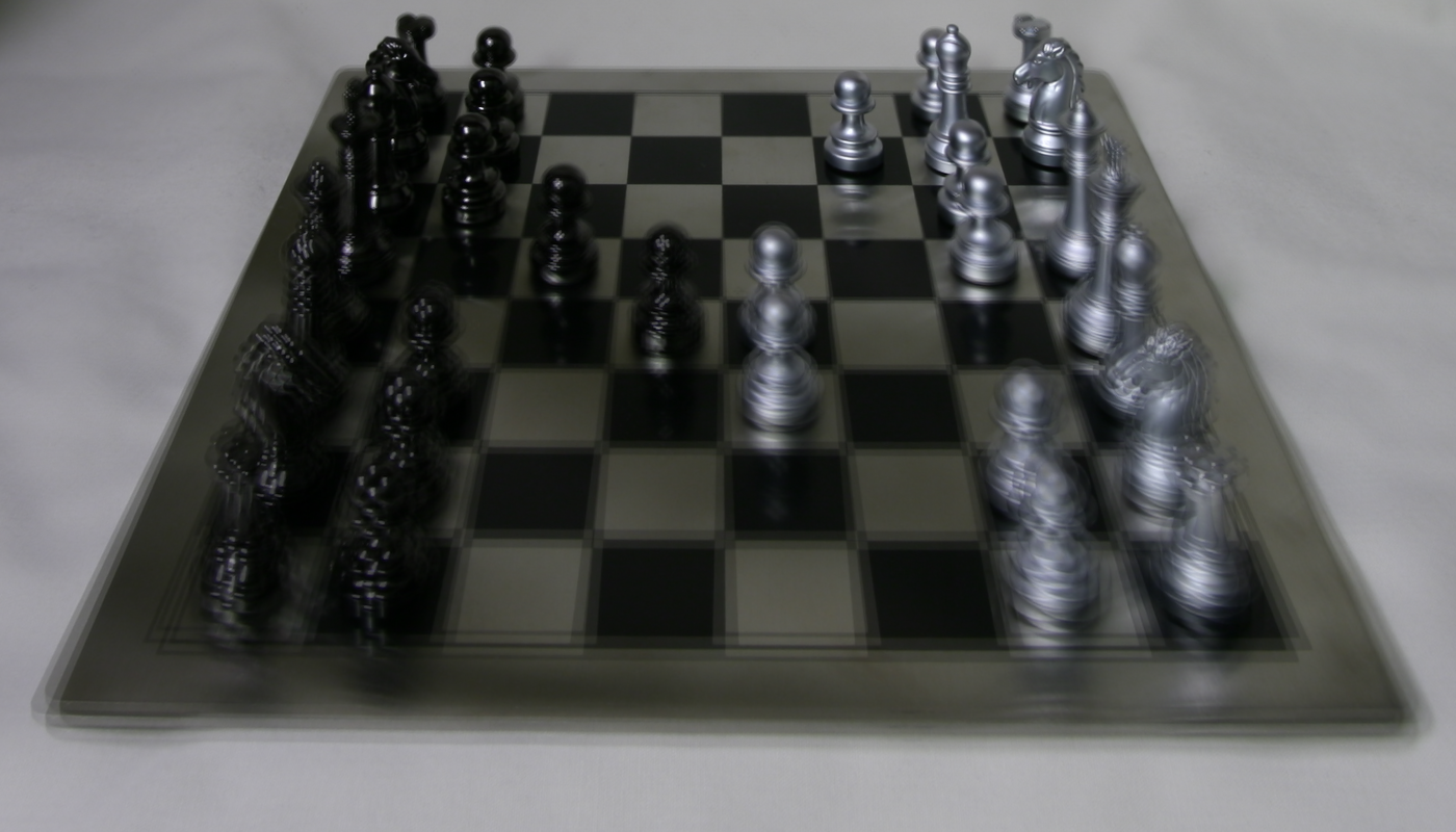
The first part of the project attempts to focus images at different points through an array of images taken from the Stanford Light Field Camera Array.
Since parallax is much more severe for areas closer to the camera compared to areas farther away, we have to account for this by shiting certain images in the lightfield camera array depending on the area of focus. This is done by simply calculating the proportional distance a given image is away from the center image of the array and applying an alpha factor to the shift in order to change location of focus.
|
|
|
|
|
|
|
|
|
|
|
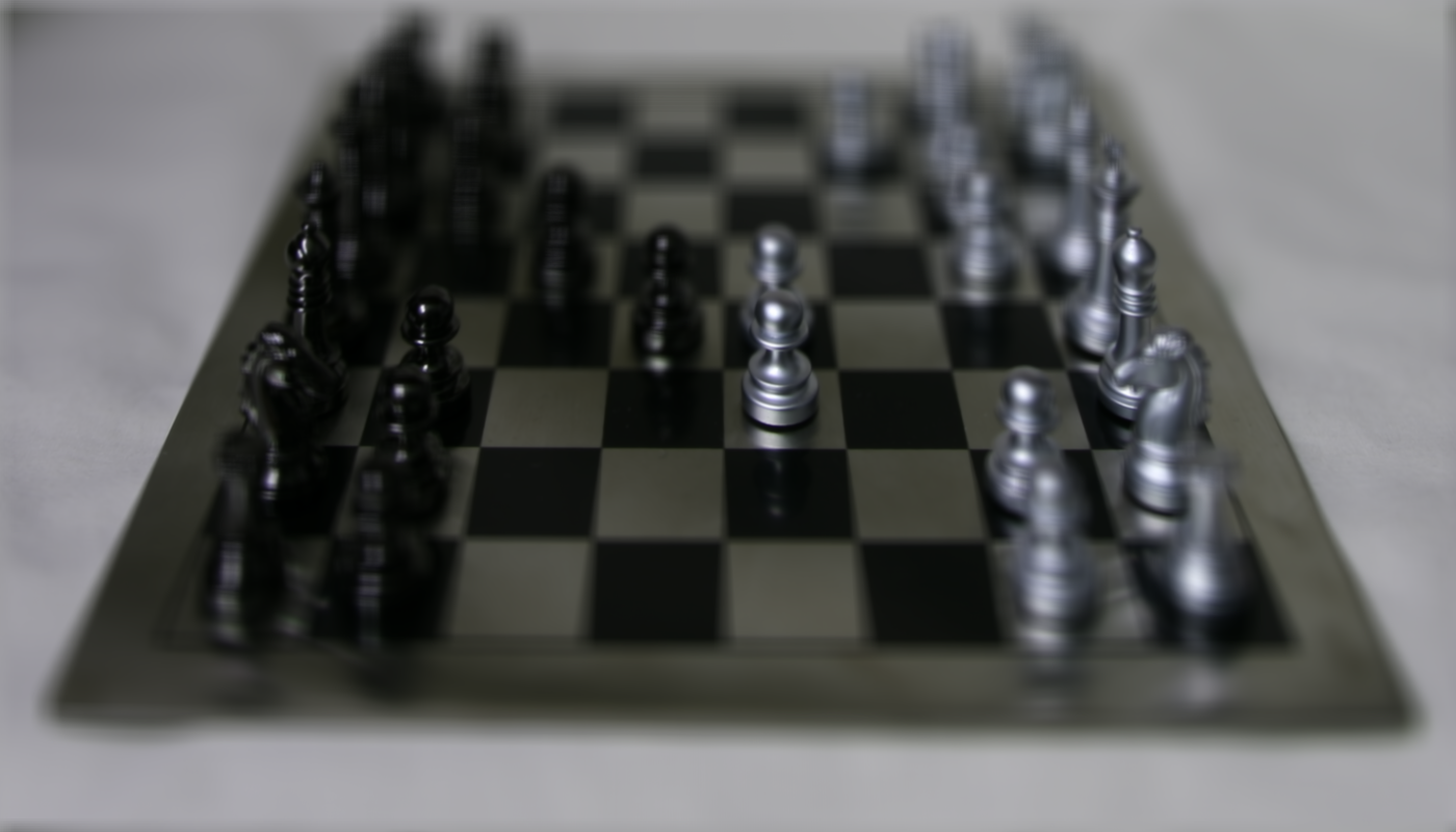
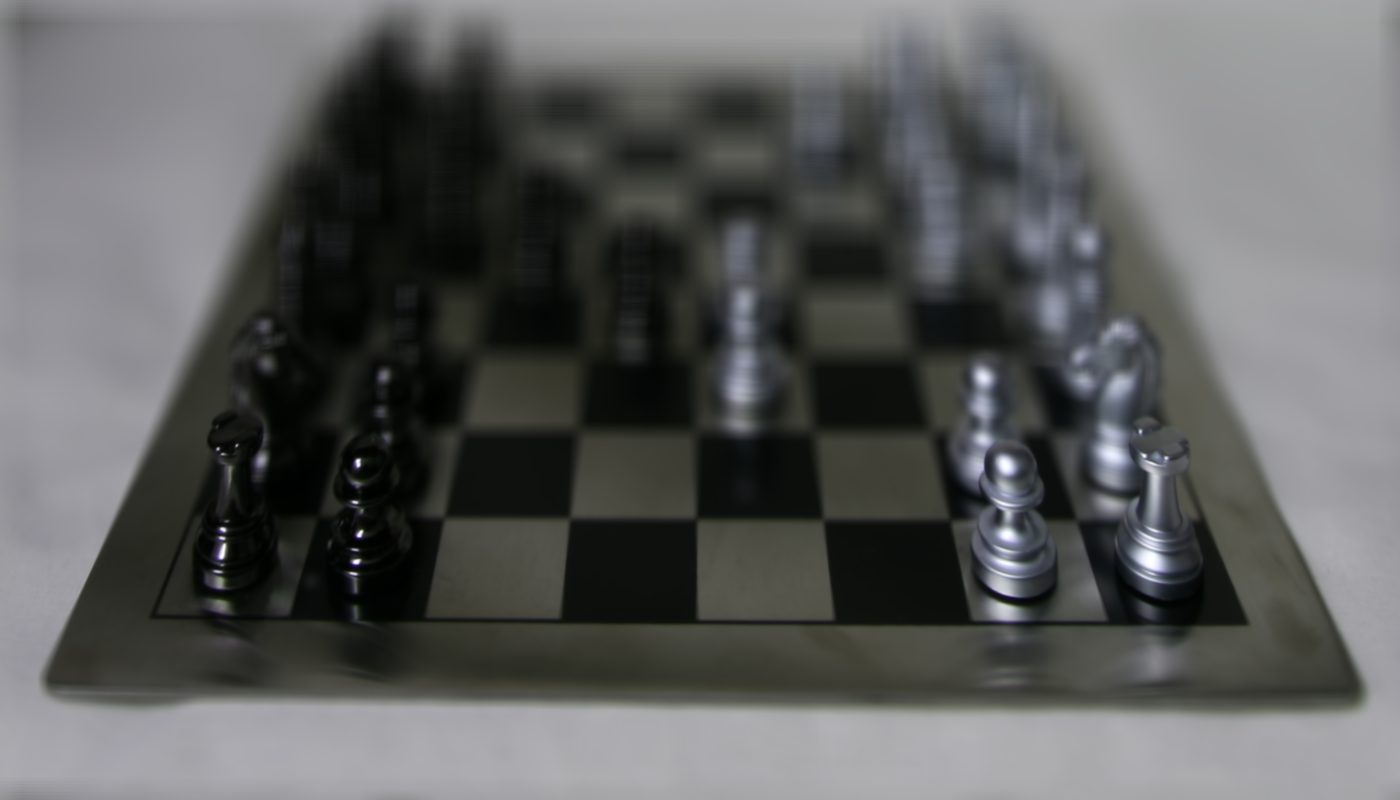
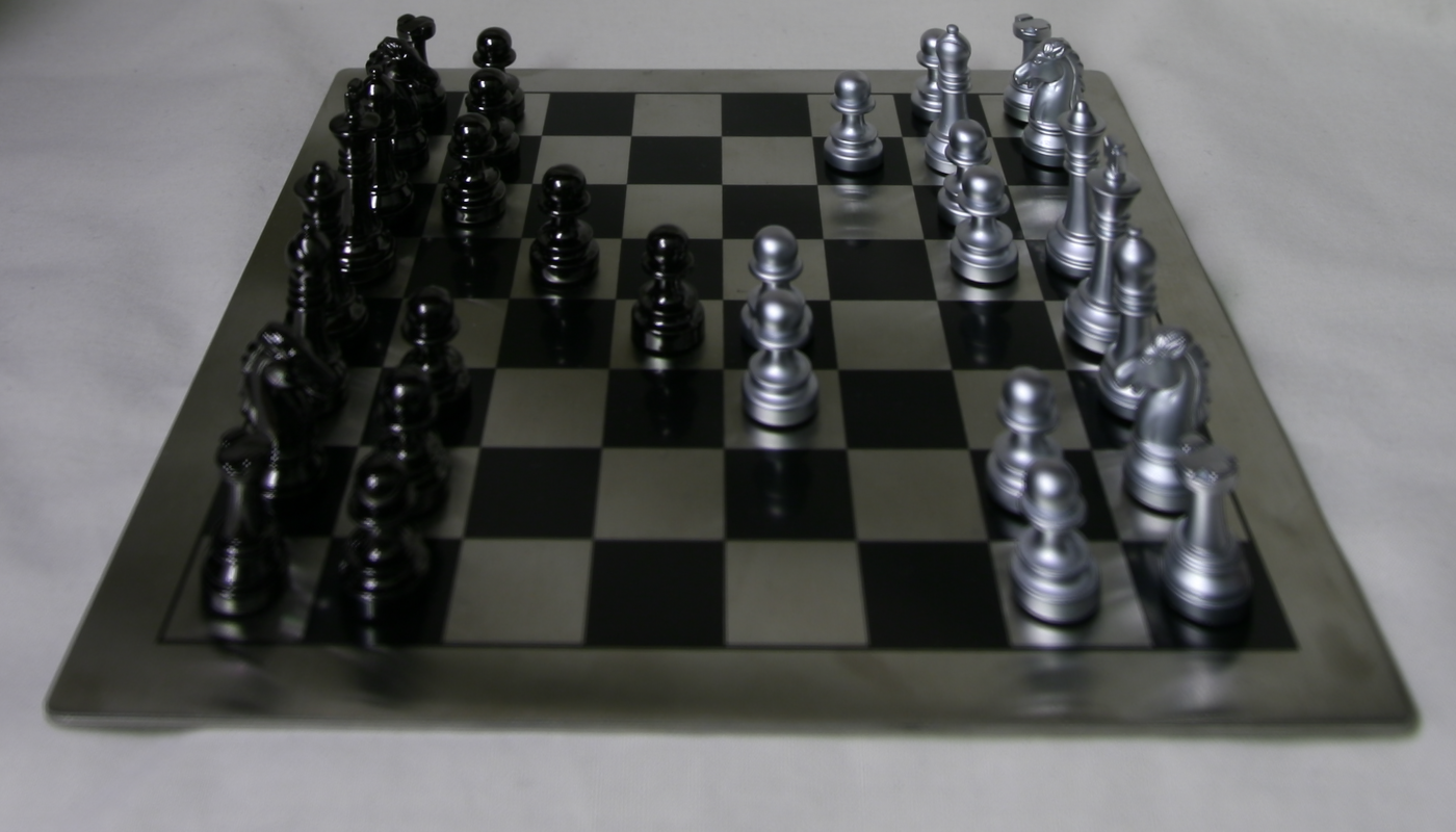
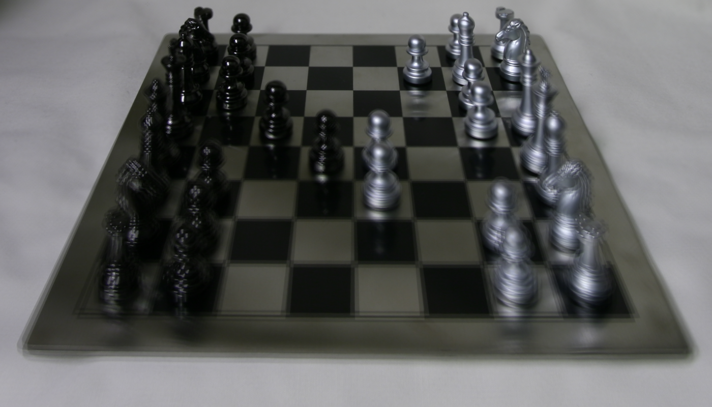
We can simulate an increase in aperture by averaging images taken in a radius around the center image, as if increasing our aperture size. Below are images of averaged photos, simulating varying aperture sizes:
|
|

|
|
|
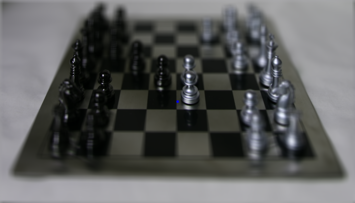
We can find the optimal alpha values for a given point on the image by using SSD on a boundary surrounding the target to compare alpha values and see value grants us boundaries that line up the best. Below are images focused on the blue dot, calculated with a boundary box of 100 pixels.

|
|

|
First I drew marking lines across a box to designate keypoints. Then, after manually selecting clear areas (corners of each grid box), I applied a median tracker to track these points across the duration of the video. Below is the result:
After removing points that did not track well, I moved onto creating the corresponding camera matrix for each frame
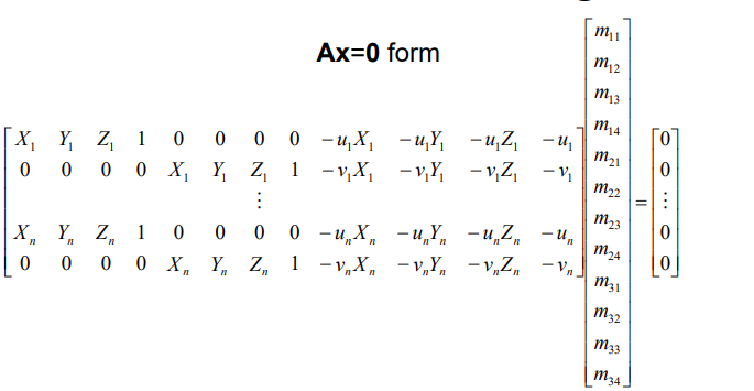
A similar method of calculating homographies was used. By using the below matrix and setting the last column to 0 for A and the last row to 0 for X and running least squares on each frame's tracked points with their corresponding world coordinates, I was able to generate a camera matrix for each frame. As a result, by applying that camera matrix to a cube in world coordinates, I was able to project a cube that aligned with the faces of the box on all frames.
|