Lightfield Camera

Table of Contents

1 Introduction

In this project, I implemented Lightfield Camera. In his paper written back in 2005 at Stanford, Ren Ng and his colleagues wanted to see if depth of field and aperture could be adjusted in post process, which normally would be almost impossible to do. Specifically this could allow for refocusing blurry images as well as allow all subject in a image to be perfectly visible. I used the data they provided in the Stanford Light Field Archive and demonstrated the computations necessary to achieve the aforementioned effects using simple algorithms.

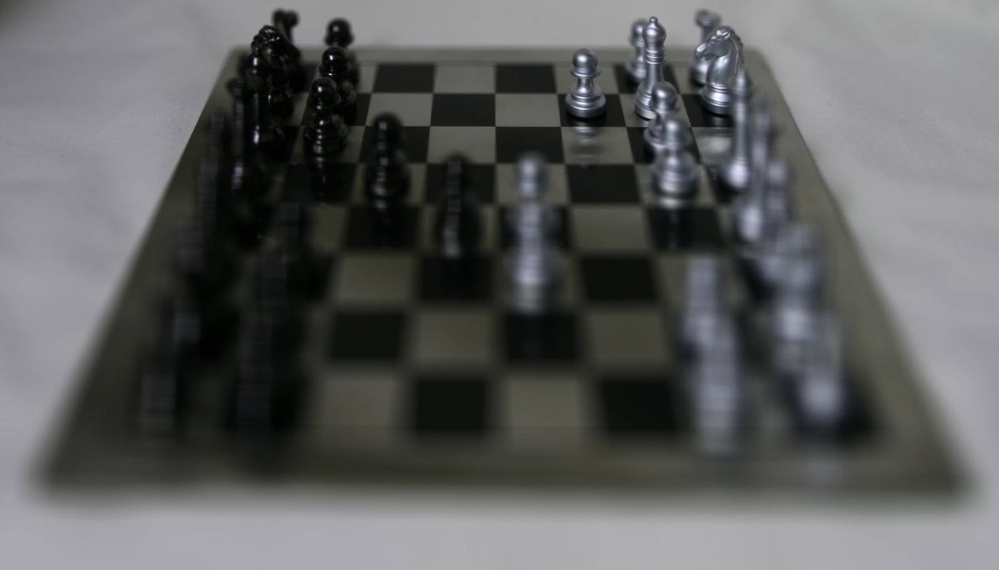
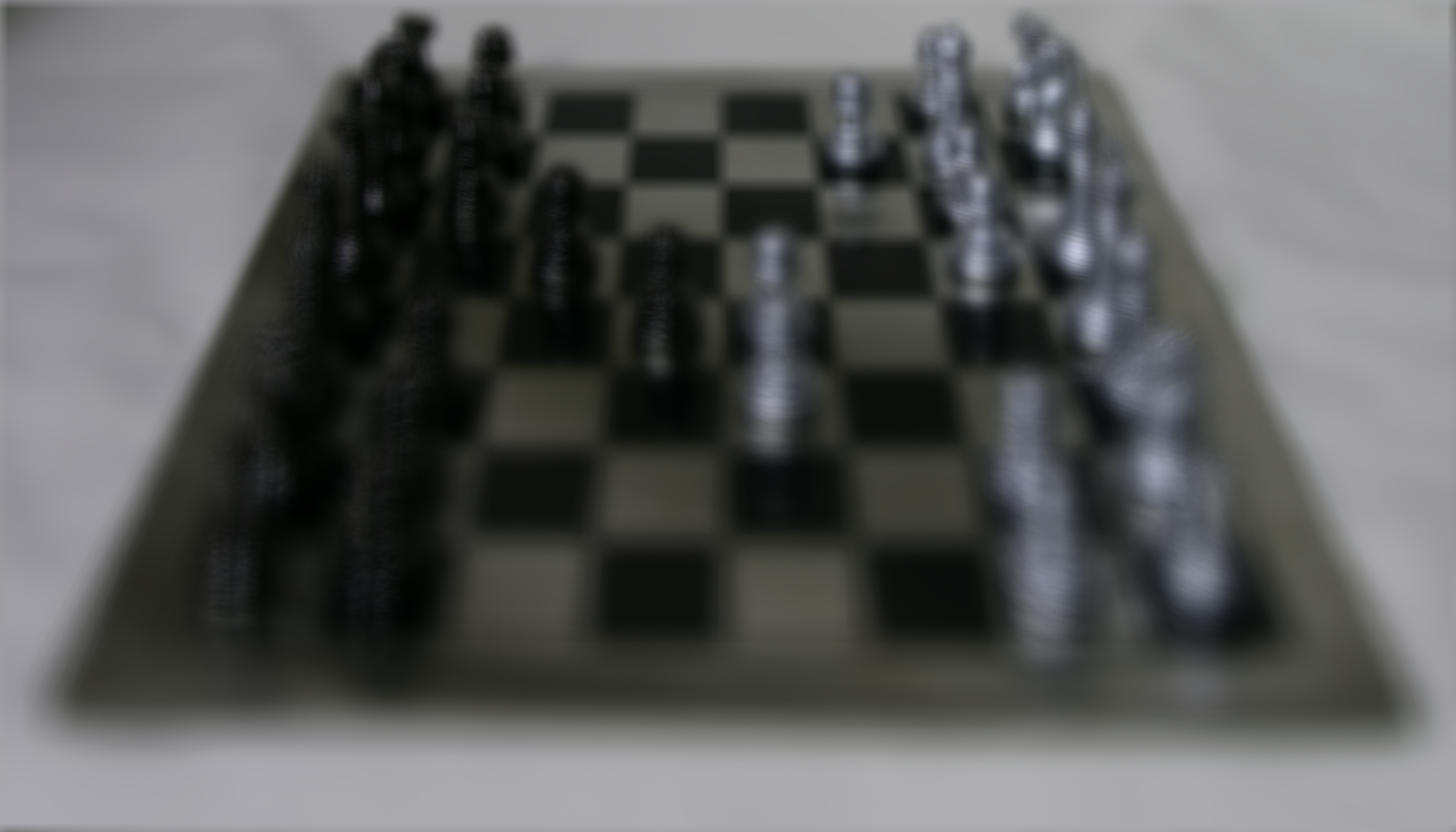
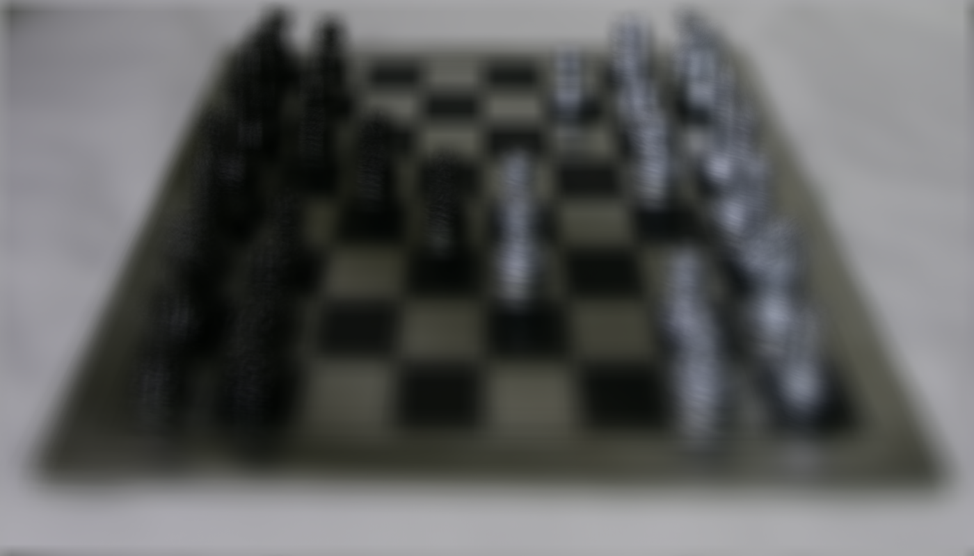
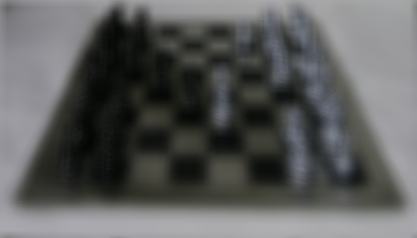
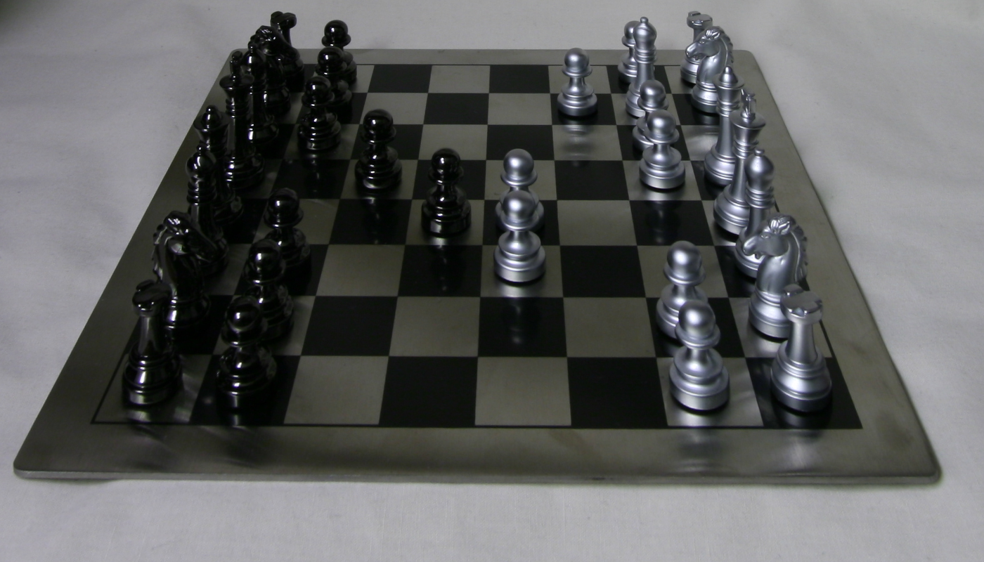
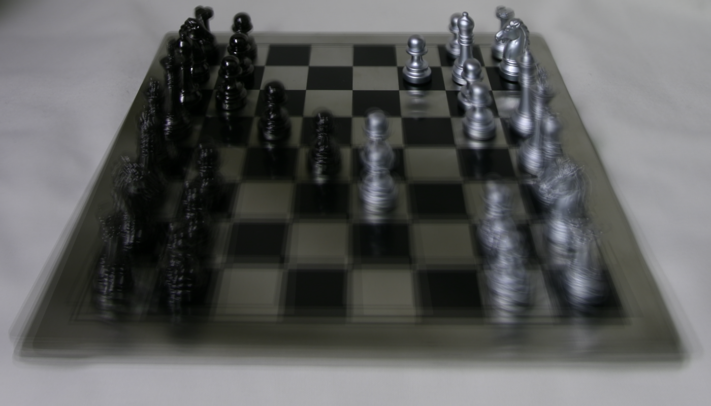
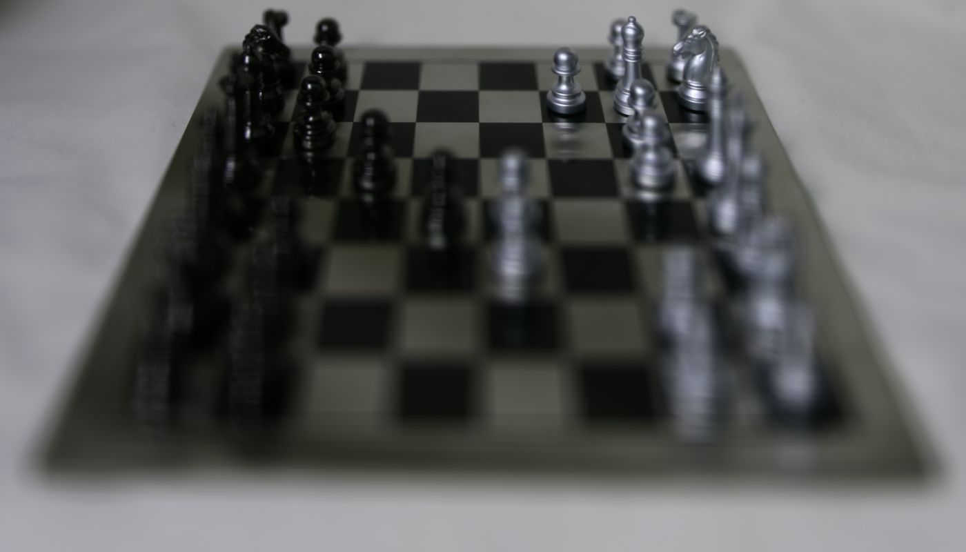
Below are some results of depth focusing.

2 Depth Focusing

Objects farther away in an image do not appear to change much when a person varies their position as opposed to foreground object. This principle is one of the main reasons why it's easy for us to determine if an object is father away from us when we move. If we average all the images in the dataset together we end up with an image with sharp far away objects and blurry nearby ones. To get around this, and to sharpen foreground objects we simply center the image around a center image, and then we shift the images that surround it (which range from [-8, 8] given a 17 by 17 array) by the amount we would like to adjust the depth focus by. In this is I used a range of [-3, 1] with step values of 1. This took around 5 minutes make the images.

rio-26.png rio-27.png
carmel-07.png carmel-08.png
goldengate-03.png

3Aperture Adjustment

By averaging a large number of images surrounding the optical axis (on a grid), we can deliminate ranges that correspond to aperture sizes. This is because in a camera the aperture get bigger and allows more light in which is very similar to allowing a larger range of image ranges to contribute to our average image. Similarly a smaller aperture would correspond to decreasing the amount of light in an image, and thus mean to decrease the range of images contributing to our average.

Below are some examples of the aperture adjustment.

rio-26.png rio-27.png
carmel-07.png carmel-08.png
goldengate-03.pnggoldengate-03.png
goldengate-03.png

4Summary

This was a really fascinating project. I first heard about Lytro quite a few years ago, but didn't not really understand the technology that drives the camera. It is novel technology with really interesting mathematics behind it, and I thoroughly enjoyed the paper. It is truly beautiful thing to begin to understand the world in a way which one hasn't before.

1 Introduction

In this project, I implemented a augmented reality functionality. The basic idea is to to use 2D points in the image who 3D coordinates are known to calibrate the camera for every video frame and then use the camera projection matrix to project the 3D coordinates of a cube onto the image. If the camera calibration is correct, the cube should appear to be consistently added to each frame of the video.


2 Poor Man’s AR

2.1 Taking the Video

I drew my points and grid on a shoe box and made sure the points are clearly visible. The final video looks like this:

AR3.gif

2.2 Capturing the Points

Now, we need to capture the points, i. e. make sure we have the points camera coordinates and world coordinates for each of the frames. To do that, we follow these steps:

2.2.1 Input Points

We input all the points camera coordinates for the first frame.

track.jpg

2.2.2 Input World Coordinates

Alongside the camera coordinates, we also need the world coordinates, which are the coordinates on the box grid.

track_world.jpg

This will enable us to assign the same world coordinates throughout the frames, making the future projection stable.

2.2.3 Track points

Considering that I decided to use some tracking algorithms from OpenCV without having any prior knowledge in them, I had to program using it as a “Black Box” API. I used the CSRT Tracker as off-the-shelf tracker. This method better tracks non rectangular shapes and enlarges the selected tracking region. It uses HoG (Histogram of Gradient) and Colornames as its standard features.

By the end of the tracking phase, we had all the needed coordinates as this video shows:

tracking.gif

2.3 Calibrating the Camera

Once you have the 2D image coordinates of marked points and their corresponding 3D coordinates, use least squares to fit the camera projection matrix to project the 4 dimensional real world coordinates (homogenous coordinates) to 3 dimensional image coordinates (again, homogenous coordinates).

We do this for every frame to map the world position to the perceived camera position.

2.4 Drawing a Cube

Now that we have this, we can simply map every point of a cube from the world position to their rendered camera position for every frame. I redered a cube with vertex positions [[1,2,0], [1,2,1], [2,2,1], [2,2,0], [1,3,0],[1,3,1],[2,3,1],[2,3,0]] and it turned out like this:

geom.gif

2.5 What I Learned

I love playing AR games but never know the theory behind it. Thank this project, I learned that the AR is based on simple image manipulation tricks. Of course, the real AR must be a lot more difficult than this. I would absolutely like to delve deeper in the future.