For my final project, I chose to complete the precanned options Augmented Reality (AR) and Image Quilting.
In this augmented reality project, I captured a video and inserted a synthetic object into the scene! The basic idea was to use 2D points in the image whose 3D coordinates were known to calibrate the camera for every video frame and then use the camera projection matrix to project the 3D coordinates of a cube onto the image.
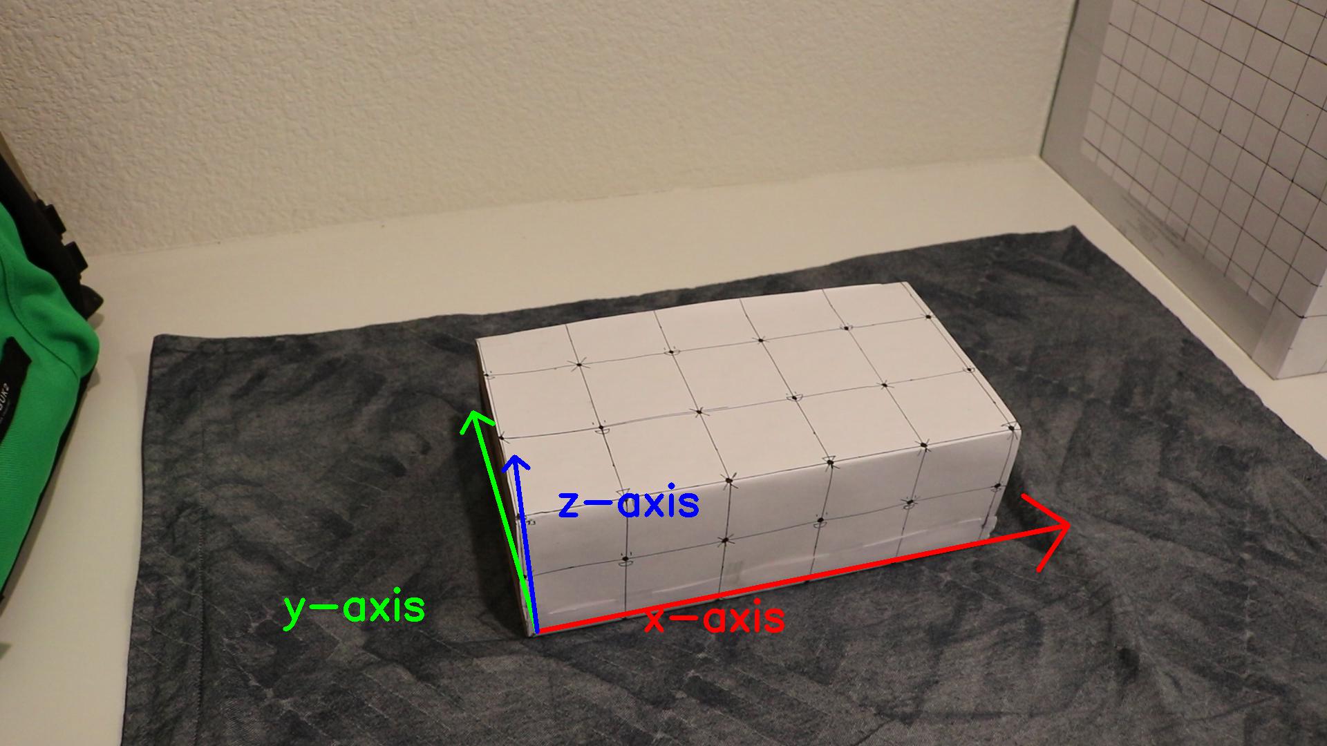
First, I found a flat surface and placed a box on that surface. I drew a regular pattern on the box. Then, I chose 27 reference points on the box, some of which were on different planes, and recorded their 3D positions. Finally, I took a short video of the box from some different viewpoints. That video is shown below:
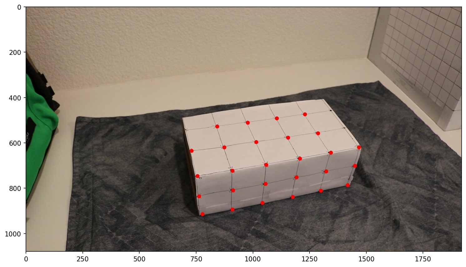
I extracted the very first frame of the video and marked the 25 reference points on that frame. To determine their 3D coordinates, I treated the bottom left corner of the box visible to the camera as the origin (0, 0, 0) and used a coordinate as shown below (per the right hand rule), where unit 1 = 1 inch in reality.
Coordinate system:
2D reference points:
The next thing to do was propagate those reference points to every frame in the video. I chose to do this with an off-the-shelf tracker. As suggested in the project spec, I used the MedianFlow tracker from OpenCV.After I defined a bounding box for each and every reference point in the first frame, the tracker tracked the positions of those box contents in all the succeeding frames. You can see the results here:
Once I had the 2D image coordinates of the marked points and their corresponding 3D coordinates, I used least squares to fit the camera projection matrix to project 4-dimensional real world coordinates (homogenous coordinates) to 3-dimensional image coordinates (also homogenous coordinates). I performed this step separately for each frame in the video.
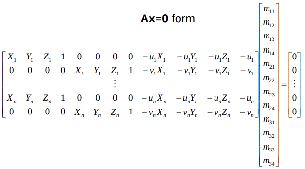
To find the unknowns comprising the projection matrix, I rewrote the camera calibration equation as a homogeneous system of equations Ax = 0 (shown below) and solved for x using least squares.
Using the camera projection matrix, I projected the axis points (8 corners of a cube) and drew a cube on each video frame image. This resulted in a cube of size 1 unit at (0,0,0). I then translated and scaled the coordinates in the axes points to place the cube at a suitable location. Once I rendered the cube independently for each image, I combined the images into a video to produce the final output result. Inspired by [2] Camera Calibration in the Resources section of the project spec.
Here is the cube at the origin before translation:
And here is the final result: the cube translated to sit atop the box.
In this project, I implemented the image quilting algorithm for texture synthesis and transfer, as described in a SIGGRAPH 2001 paper by Efros and Freeman. Texture synthesis is the creation of a larger texture image from a small sample. Texture transfer is giving an object the appearance of having the same texture as a sample while preserving its basic shape. For texture synthesis, the main idea is to sample patches and lay them down in overlapping patterns, such that the overlapping regions are similar. The overlapping regions may not match exactly, which will result in noticeable edges. To fix this, I computed a path along pixels with similar intensities through the overlapping region and used it to select the overlapping patch from which to draw each pixel. Texture transfer is achieved by encouraging sampled patches to have similar appearance to a given target image, as well as matching overlapping regions of already sampled patches.
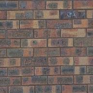
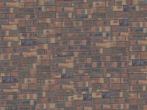
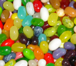
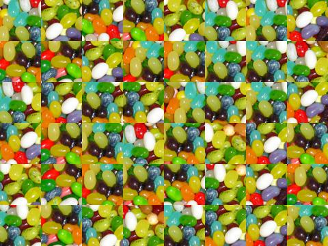
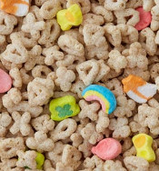
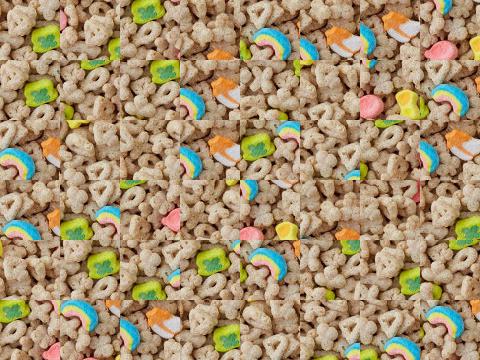
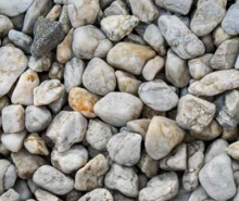
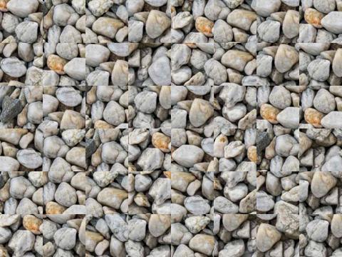
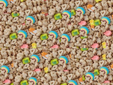
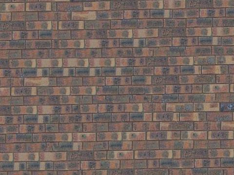
First, I created a function that randomly samples square patches from a sample in order to create a larger output image. The algorithm starts from the upper-left corner, and tiles samples until the image is full. This is the simplest but least effective method. Below are the results of my function on a few sample images:
| Sample | Result |
|---|---|
 |
 |
 |
 |
 |
 |
 |
 |
 |
 |
 |
 |
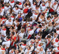
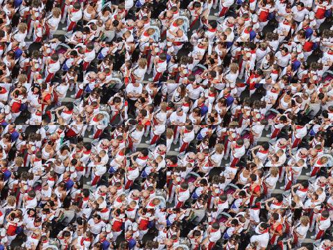
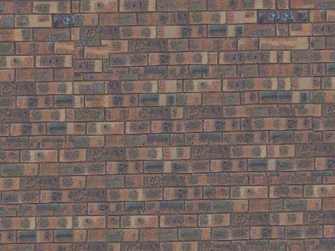
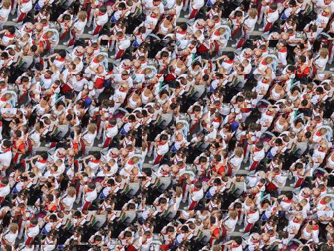
Next, I created a function that randomly samples the upper-left corner, and then samples new patches to overlap with existing ones. Once the SSD overlap cost of each patch has been computed, it randomly chooses one patch whose cost is less than a certain threshold.
To calculate the sum of squared differences (SSD) for overlapping regions of the existing and sampled patch, I used a masked template. The template is the patch in the current output image that is to be filled in (many pixel values will be 0 because they are not filled in yet). The mask has the same size as the patch template and has values of 1 in the overlapping region and values of 0 elsewhere. With this mask, I produce an image in which the output is the overlap cost (SSD) of choosing a sample anchored at each pixel (I use the upper left corner of the sample patch as the anchor). One interesting thing to note: I found that looping over the pixels was actually 4-5x faster than using the filtering operations (e.g. correlation) in scipy.
For each cost image (each pixel's value is the cost of selecting the patch anchored at that pixel), my function selects a randomly sampled patch with low cost, as described in the paper. I first find the minimum cost (minc) and then sample a patch within a percentage of that value. If the minimum is approximately zero (which can happen initially), I set minc to a minimum higher value.
Results are shown below:
| Sample | Result |
|---|---|
|
 |
|
 |
|
 |
|
 |
|
 |
|
 |
cut function)To further improve my results, I incorporated seam finding to remove edge artifacts from the overlapping patches (section 2.1 of the paper). This involved writing my own function cut(bndcost) that finds the min-cost contiguous path from the left to right side of the patch according to the cost indicated by bndcost. The cost of a path through each pixel is the square differences (summed over RGB for color images) of the output image and the newly sampled patch. The cut function uses dynamic programming to find the min-cost path and define a binary mask that specifies which pixels to copy from the newly sampled patch. If a patch has top and left overlaps, I compute two seams, and define the mask as the intersection of the masks for each seam.
The dynamic programming relationship for cut is essentially:
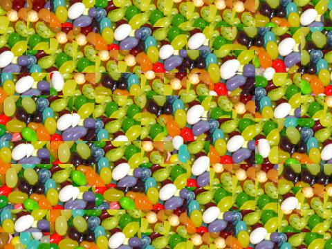
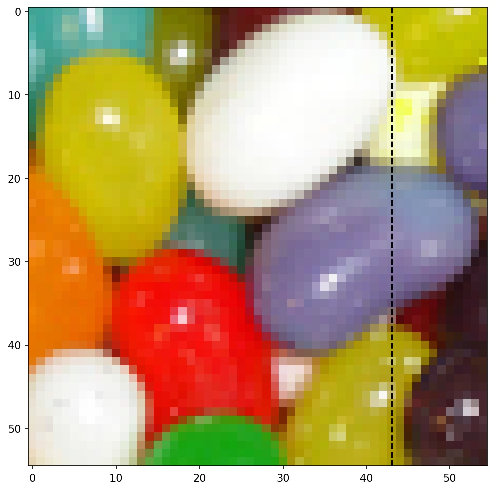
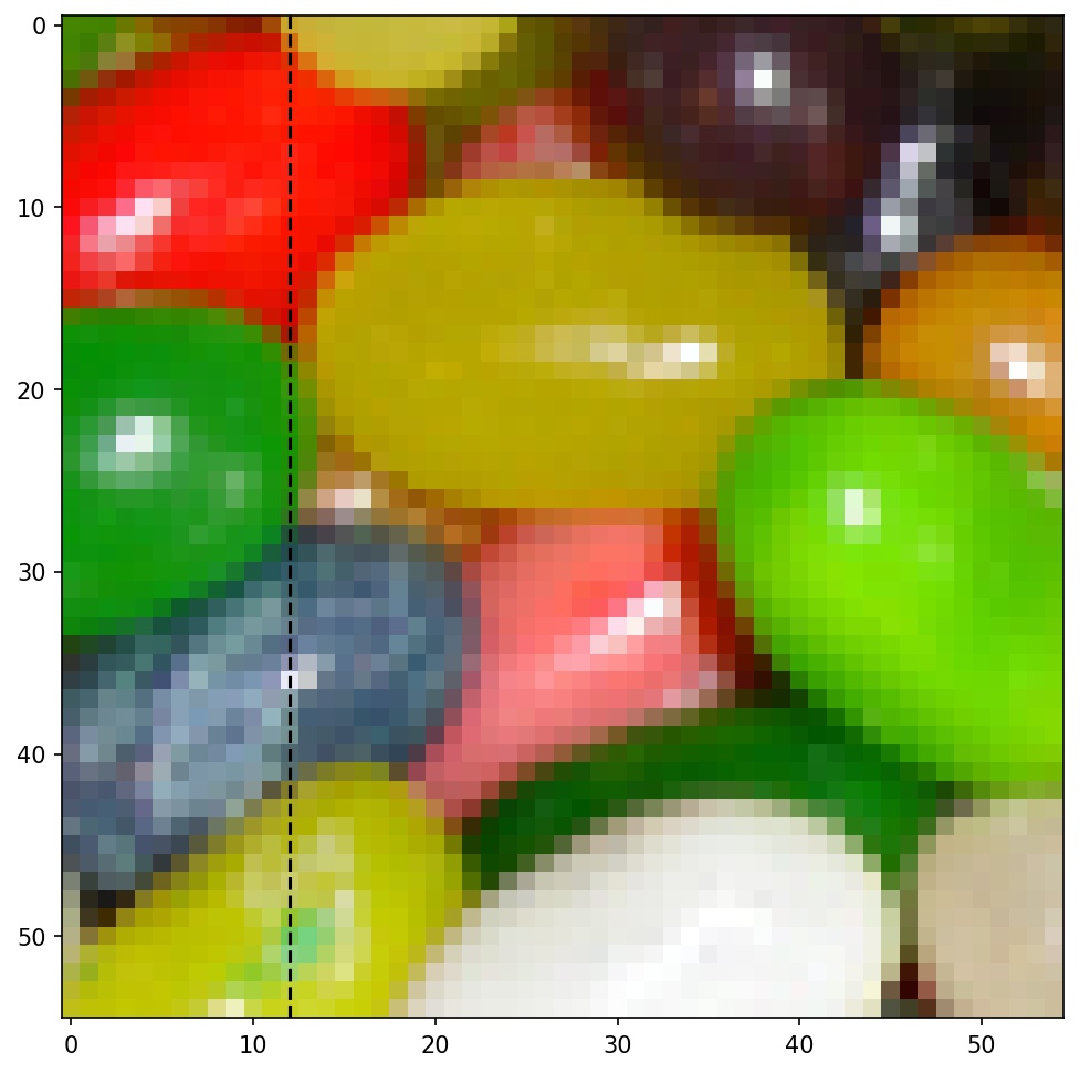
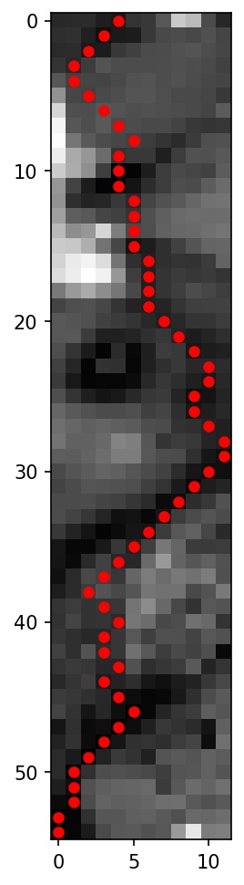
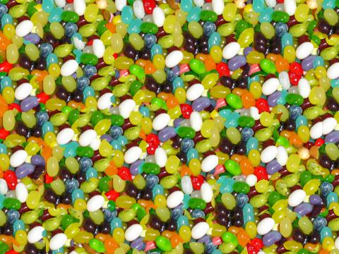
Below is an example of a seam found using my cut function between two overlapping patches of jelly beans.
| Overlapping Patch 1 | Overlapping Patch 2 | Overlap Error + Min-cut Path | Stitched Result |
|---|---|---|---|
 |
 |
 |
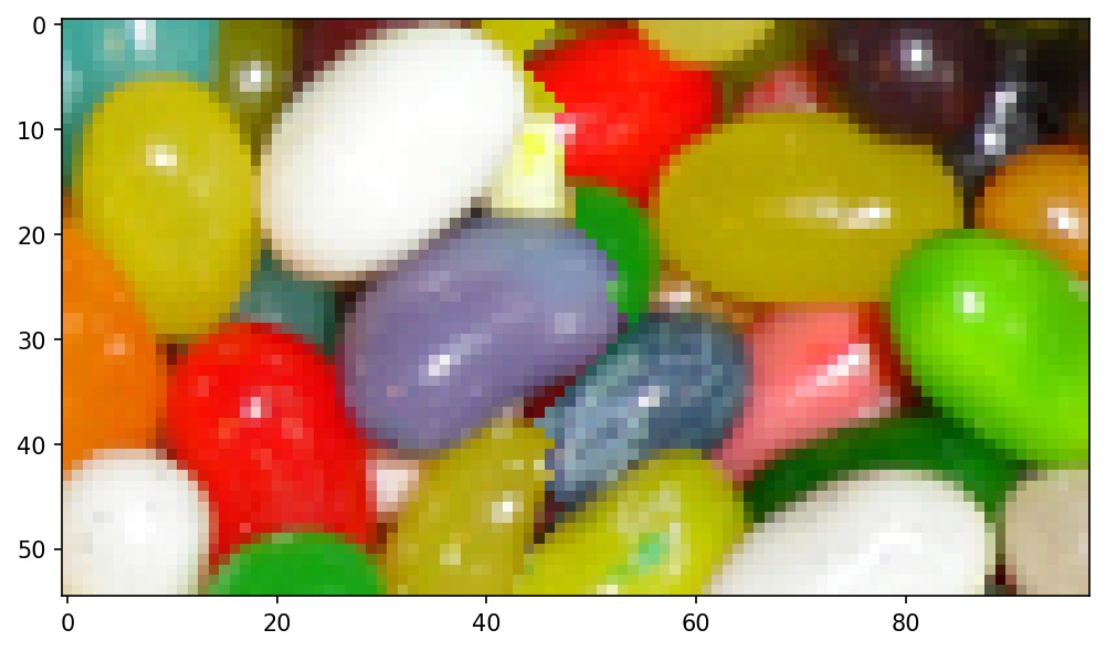 |
Above is an illustration of seam-finding, which is used for texture synthesis. As before, the area of the output image is filled sequentially with small, overlapping, square patches chosen from the sample image. To get rid of obvious seams and make the whole output look natural, we choose each patch such that the SSD of its overlapping area w.r.t. its left and upper neigbors is minimized within some tolerance. Once this is done, instead of using the middle line as a dividing border between overlapping patches, we use the seam finding algorithm above to find a border that minimizes the SSD of pixels along said border, leading to a less noticeable cut. The image above images show an example of two overlapping jellybean patches being matched and cut. Our seam-finder identifies a minimum-error cut, which is shown superimposed in red on a map of SSD error within the overlapping area. The resulting stitched image is then shown.
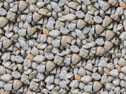
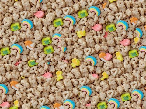
I created a function quilt_cut that incorporates seam finding. Below are some results of this function, compared side by side with earlier random and overlapping results.
Sample:
| Random | Overlap | Seam-finding |
|---|---|---|
|
|
 |
Sample:
| Random | Overlap | Seam-finding |
|---|---|---|
|
|
 |
Sample:
| Random | Overlap | Seam-finding |
|---|---|---|
|
|
 |
Sample:
| Random | Overlap | Seam-finding |
|---|---|---|
|
|
 |
Sample:
| Random | Overlap | Seam-finding |
|---|---|---|
|
|
 |
Sample:
| Random | Overlap | Seam-finding |
|---|---|---|
|
|
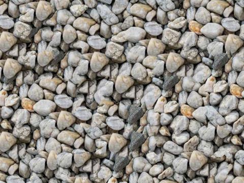 |
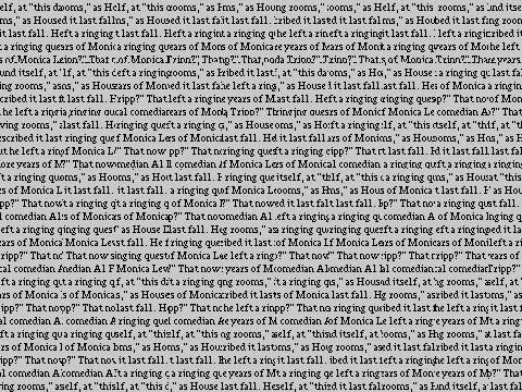
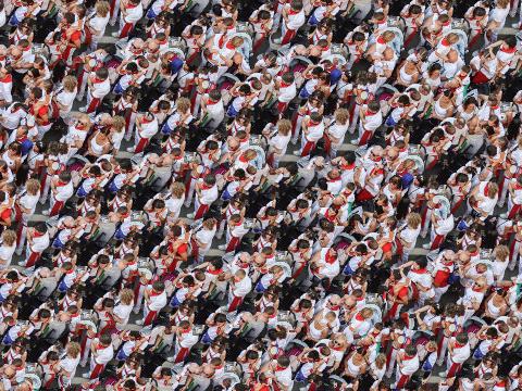
I created a texture transfer function based on quilt_cut for creating a texture sample that is guided by a pair of sample/target correspondence images (section 3 of the paper). The main difference between this function and quilt_cut is that there is an additional cost term based on the difference between the sampled source patch and the target patch at the location to be filled.
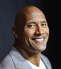
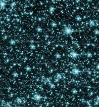
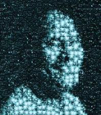
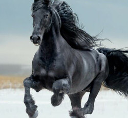
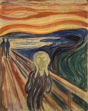
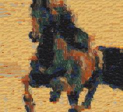
Texture transfer is a specialized form of texture synthesis where patch selection not only minimizes SSD overlap error between adjacent patches, but also tries to choose patches that minimize SSD error in comparison to a target image map. These two parts of the objective function are balanced by an alpha parameter, which determines how much weight is given to each of these goals. If the parameters are well chosen, the result will be a good-looking texture synthesis that also contains a faithful reproduction of some features of the target image. Examples are shown below.
| Target | Sample | Result |
|---|---|---|
 |
 |
 |
 |
 |
 |
 |
 |
 |
cut functionAs mentioned above, I wrote my own cut function in Python. I did not reference any existing code. The recurrence relationship I devised and used is as follows:
I took a bottom-up dynamic programming approach to solve this problem.
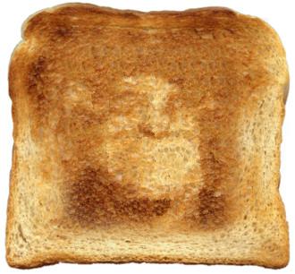
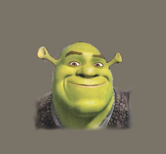
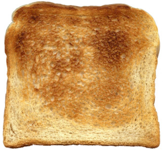
As a second Bells and Whistles, I used a combination of texture transfer and blending to create a face-in-toast image of Shrek, the famous Dreamworks animations character. First, I performed a texture transfer operation with Shrek's face as the target map and a piece of toast as the texture. Then, I applied three-layer Laplacian pyramid blending to make the image more natural-looking. Note: Shrek's face is even more visible if you look at it from far away :-)
| Shrek | Toast | Filter |
|---|---|---|
 |
 |
 |
Shrek Toast:
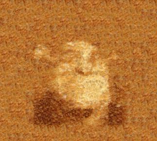
Shrek in Toast (with Laplacian Blending):