Two individual projects: Lightfield Camera and Image Quilting
Lightfield Camera
Overview
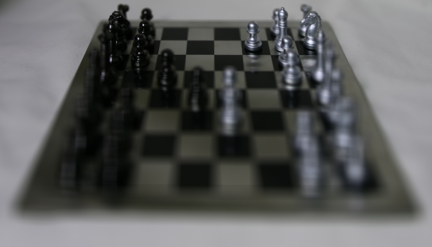
This project involved using images from Stanford Light Field Archive that represented the different parts of a light field in order to refocus the depth and adjust the aperture. Each image represents a single cell in a grid that represents the light field.
Depth Refocusing
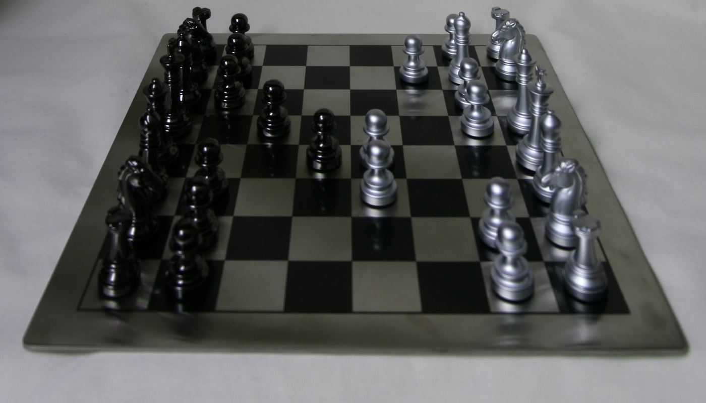
By simply averaging all of the images together, this produces an image that is blurring everywhere except for the very back. This is because the objects in the back don't move around as much when the camera is shifted, resulting in the most blurring at the front.
Averaged image without shifting
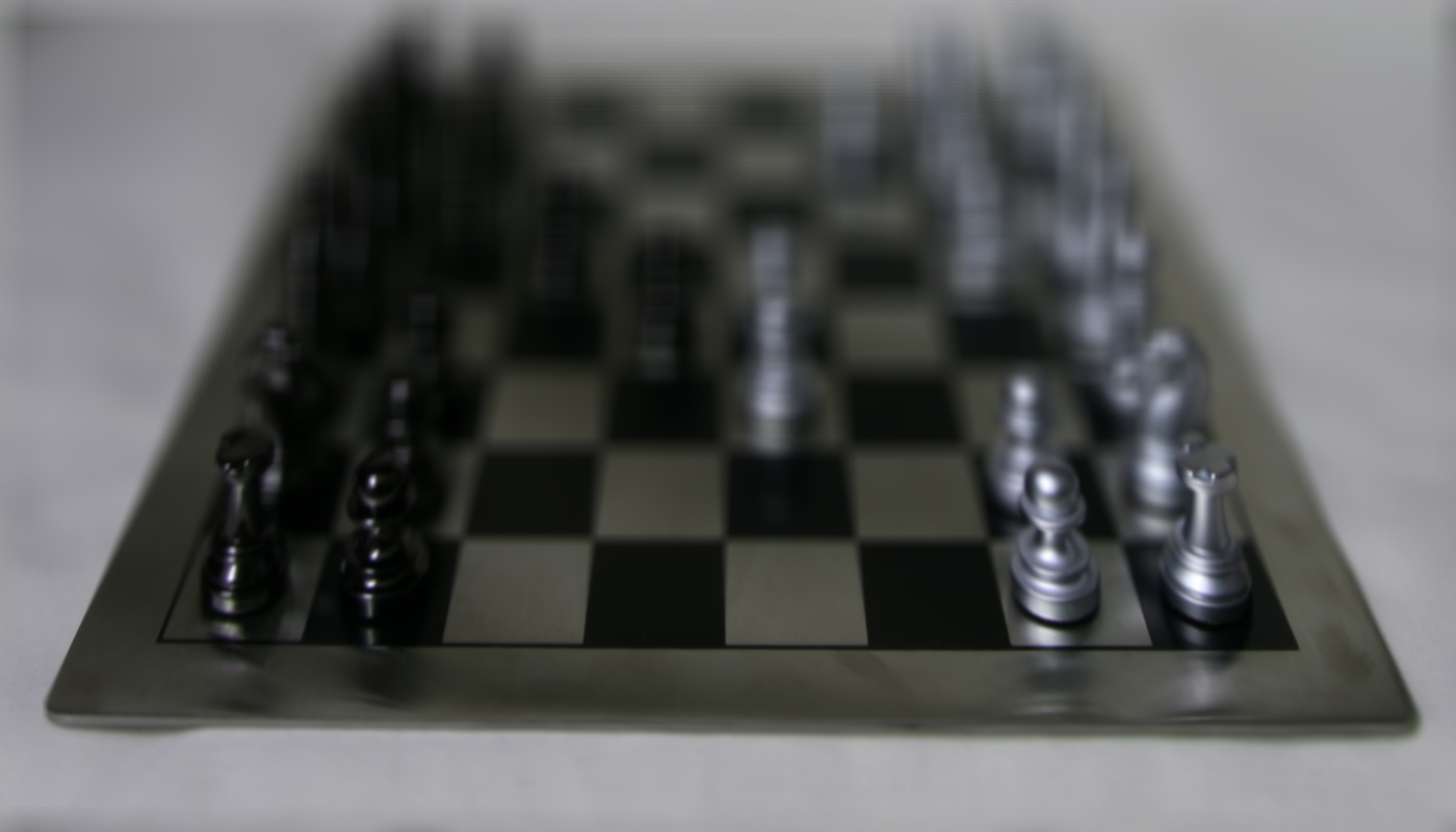
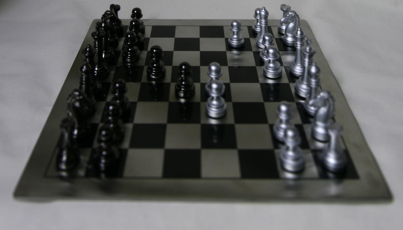
The original images were not in sorted order, but by looking at the names of the files I was able to arrange in a 17x17 grid that formed the light field matrix. Once in this format, I was able to adjust the depth by calculating the difference of each image to the average center and shifting the image by a factor controlled by a parameter. The value of this parameter controls which parts of the image become in focus and which parts of the image become blurry. I found the optimal values of this parameter to be from 0 to 3.
Front focusedMiddle FocusedA gif of many different depths
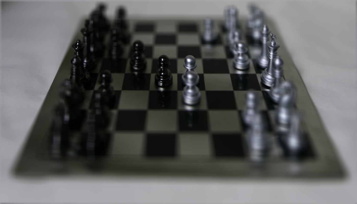
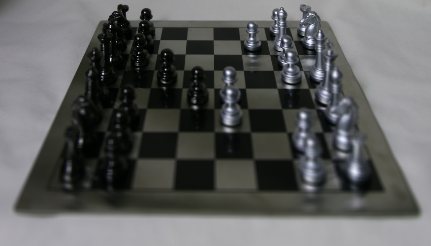
Aperture Adjustment
The Aperture is adjusted by averaging the pictures within a certain radius from the center of the light field grid.
Radius 1Radius 2Radius 3
Summary
It was great learning about how light fields work and that the position of an image within the lightfield can be used to adjust the depth and aperture.
Image Quilting
Overview
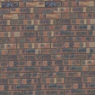
This project involves creating a quilt of textures from a sample source image as well as transfering textures onto other images. This is done through comparing SSDs of the source and destination patches. The seams between patches are found using dynamic programming.
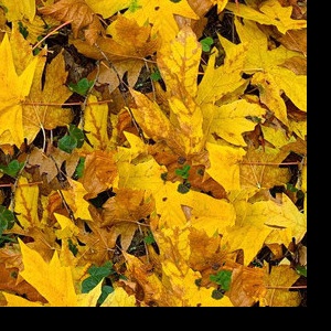
Randomly Sampled Texture
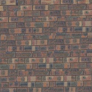
Here I just randomly sampled from the source texture to create patches that were quilted together.
Brick random sampling
Overlapping Patches
In order to make the quilting a bit more realistic and natural, I had to find patches that were somewhat similar to each other on the edges. An overlap is specified and the resulting overlapping regions (usually top and left) were compared to the destination image using an SSD. Patches that are within a tolerance difference to the minimum costing patch are randomly chosen.
A dynamic programming approach was used. An SSD map between the overlapping portions were calculated. Then, the starting point of the minimum path is found at the minimum of the last row or column depending on if it is a vertical or horizontal cut. Then, the entire path is traced by finding the minimum between the three upper neighbors of the last point in the path.
Here are three different outputs of the bricks source: random, overlapping, and seam-finding
Random SamplingOverlapping texturesBrick Seam
The random sampling iamge is the most chaotic one, with the lines in each patch clearly not lined up with each other. The overlapping textures takes care most of this problem, but there are still noticeable edges surrounding the patches. The seam-finding images further improves on this.
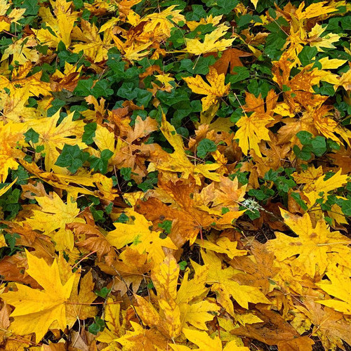
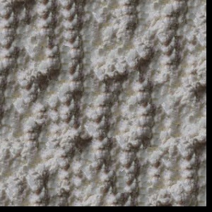
Texture Transfer
The texture of a source image is transferred to a destination by just modifying the functions to the previous parts. The error function now includes a weighted sum between the original loss and the SSD between the correspondence maps of the texture source image and controlling target image patches.
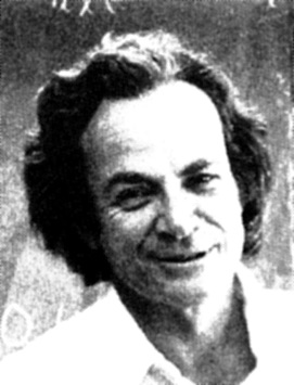
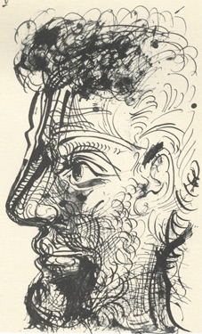
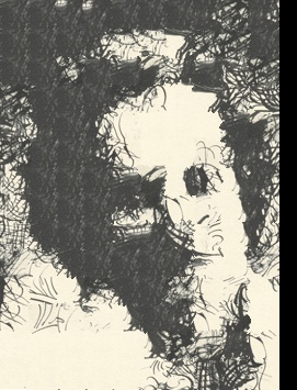
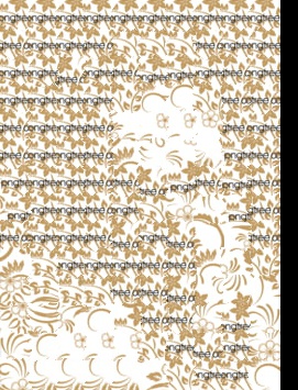
Feynman originalSketch original
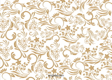
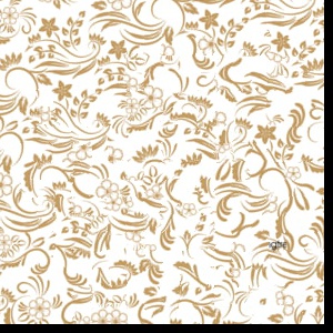
Feynman with sketch texturesFeynman withi floral textures
The second texture transfer isn't as detailed and accurate, probably due to the limitations of the floral source image. However, the general outline of the face can still be seen. One thing to note is that the alpha value had to be very high for the target image's features to become apparent.
Bells and Whistles
I implemented my own version of cut.m. I instead wrote two functions, one for the vertical path and one for the horizontal path. I would check based on the row/column numbers whether to use one or both functions. This would generate a mask that I could then apply on the source and destination patches.