High Dynamic Range Imaging
CS 194-26 Final Project 3 - Fall 2020
Glenn Wysen and Morgan Nanez
Radiance Maps
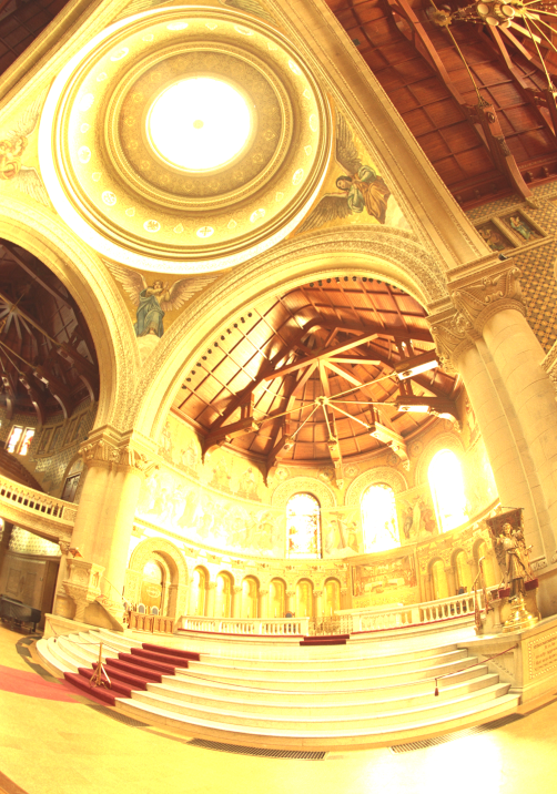
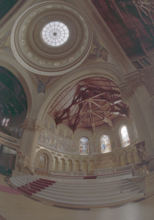
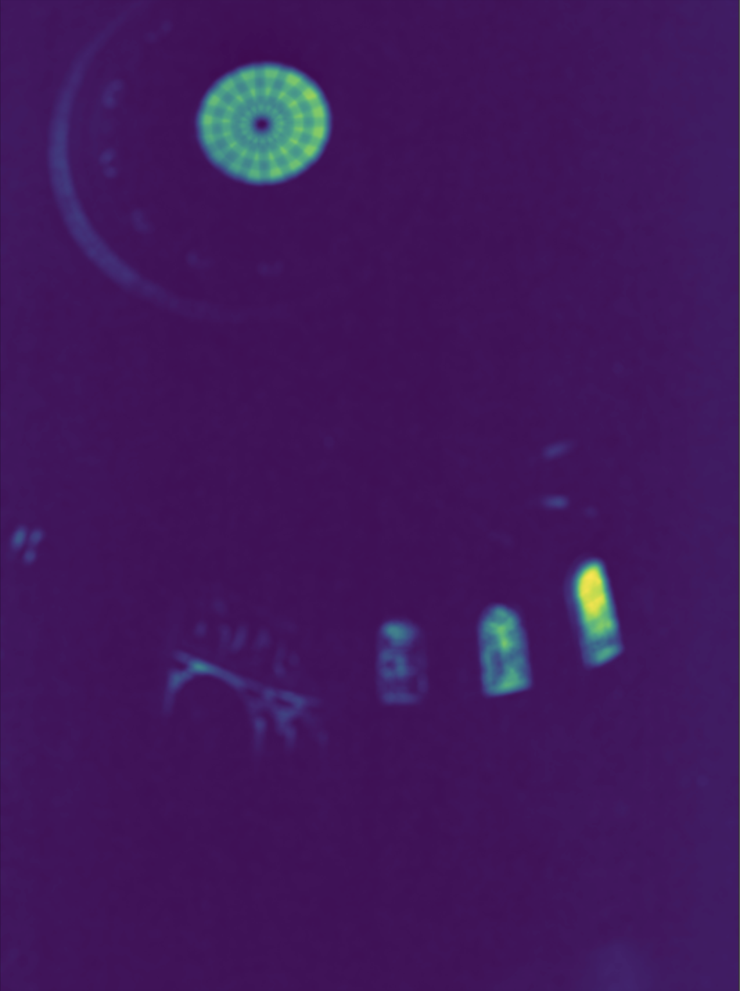
The first step to recovering an HDR image was to find radiance maps for images which represent the overall radiance from a series of images taken of the same target with different exposures. This process involved finding a relation between pixel values (range 0-255) to exposure levels (relationship shown in Fig. 3). Higher values are shown in the green/yellow while lower values are blue. Another visualization of this mapping is shown in Fig. 4 below which shows an example curve for one of the images mapping pixel values to log(intensities).

Bilateral Filtering
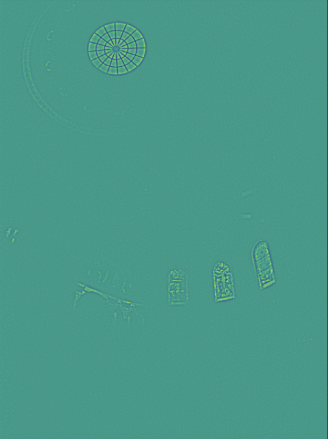
Another step in the process was performing bilateral filtering and recovering the high detail parts of the radiance maps. A visualization of these two filters for the red channel of the chapel is shown in Fig. 5 and Fig. 6 below.
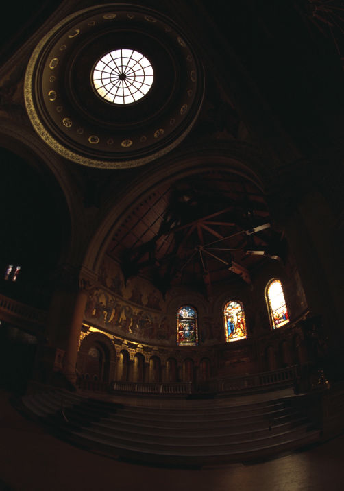
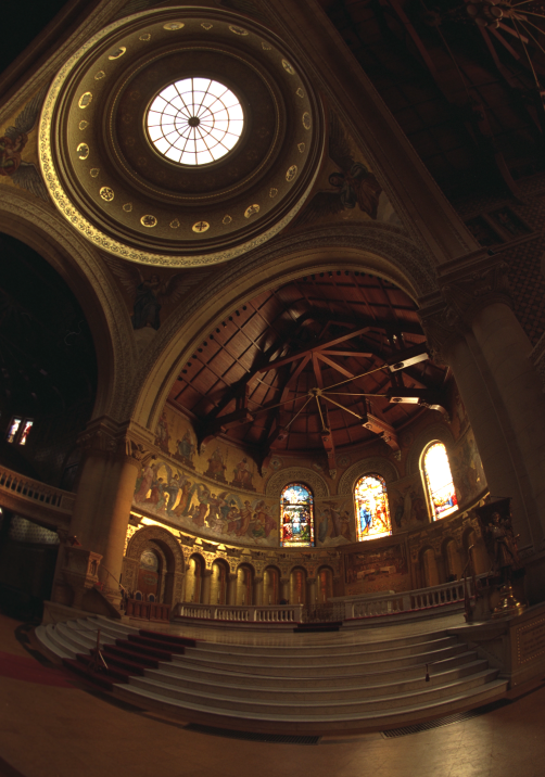
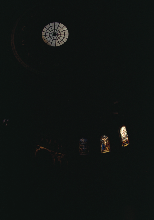
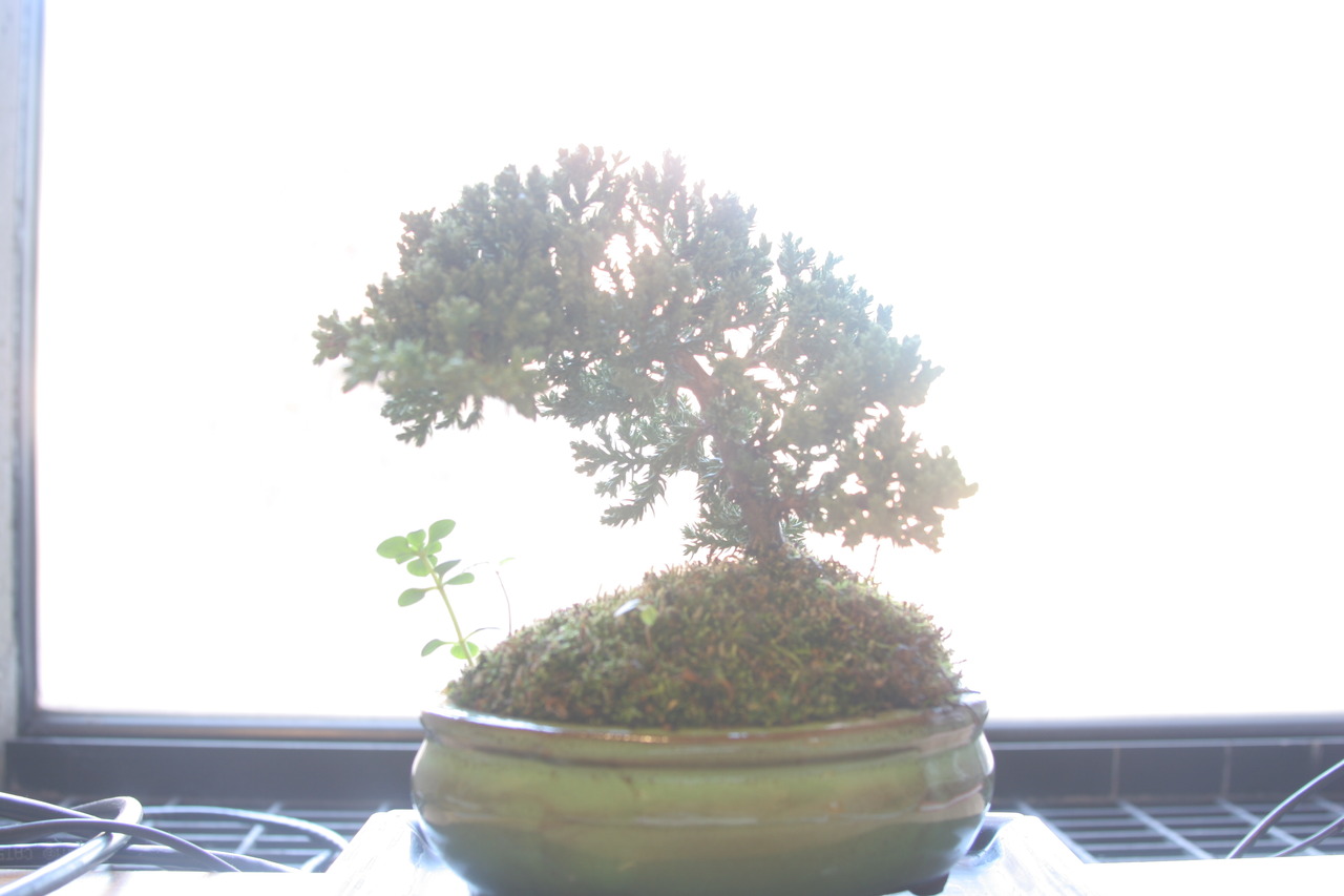
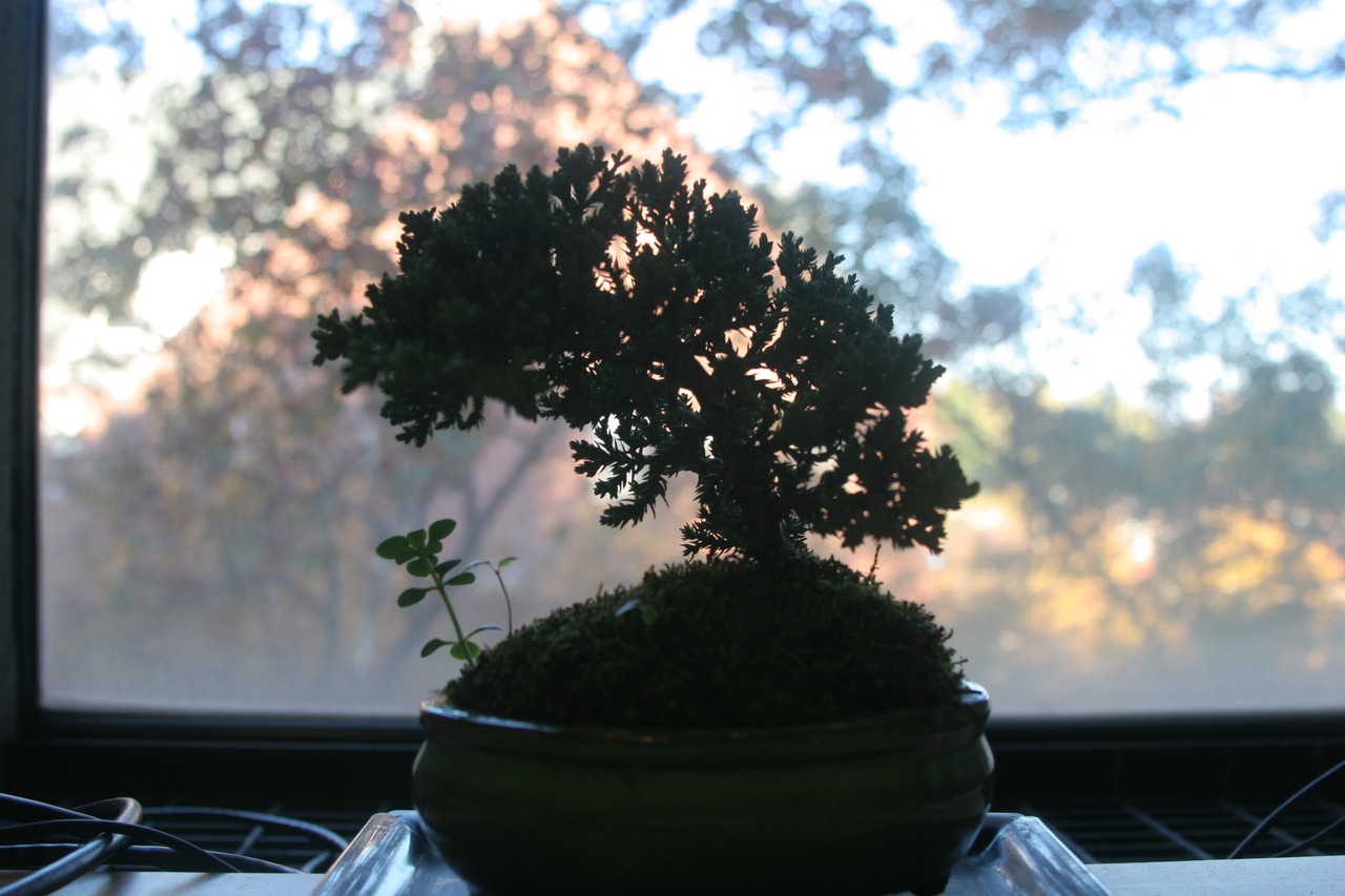
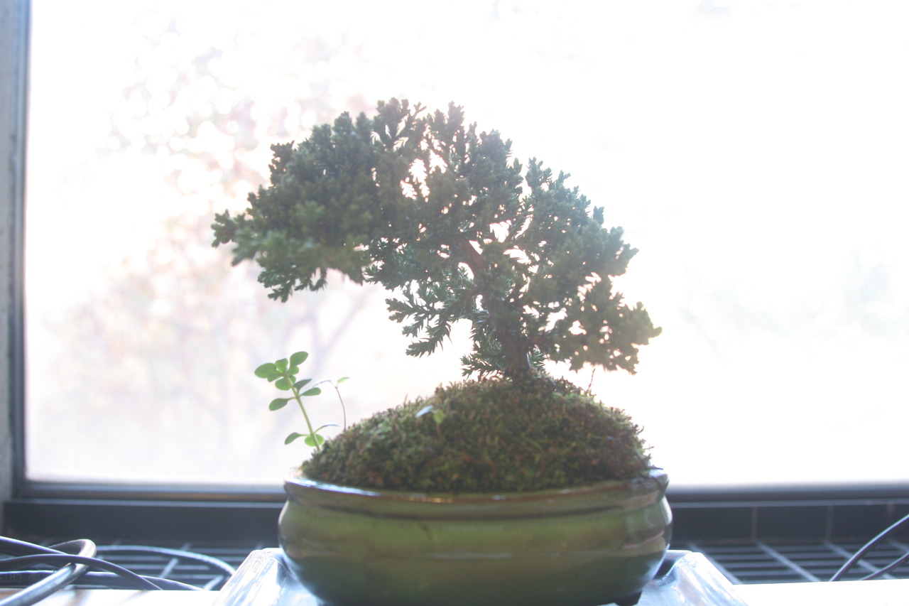
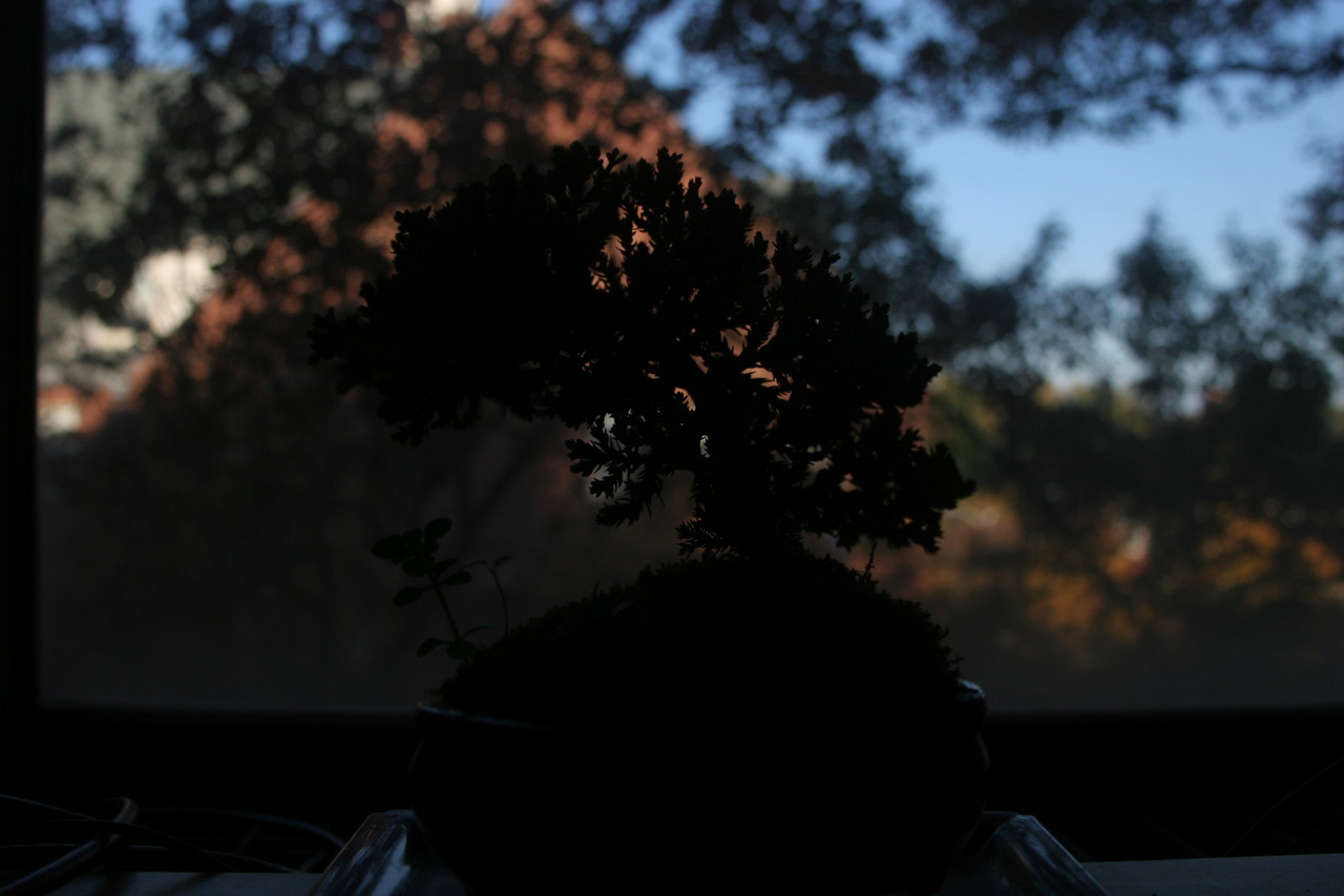
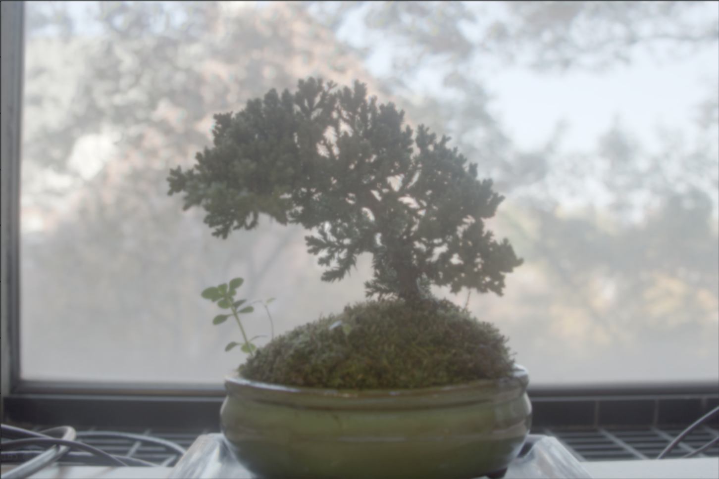
Example Results
Below are some additional results of running the whole algorithm over some sample inputs.