Overview
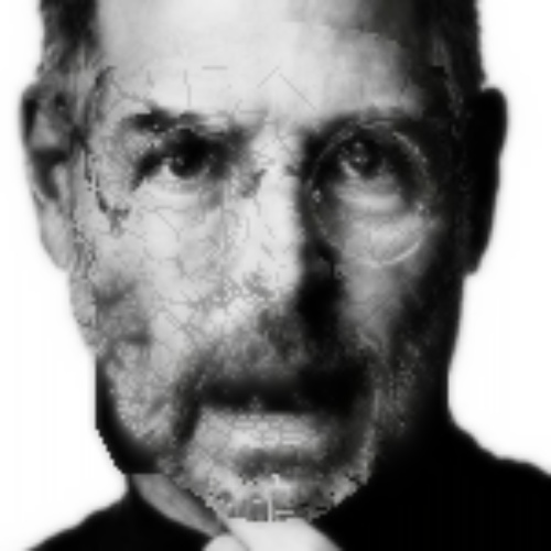
The objective of this project was to bring still photos to life by using a sample image or video as input for a target image. An example is shown below:
|
|
There were several steps in achieving the final output. Initially, I had to figure out how to model the faces. Then I had to transfer expressions from one photo to another using a reference source. Finally, I was able to synthesize videos using this technique multiple times.
Inputs & Preprocessing
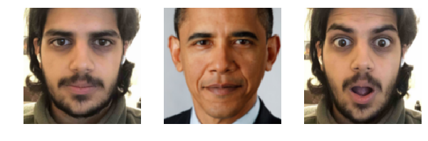
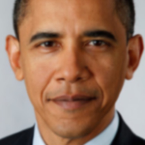
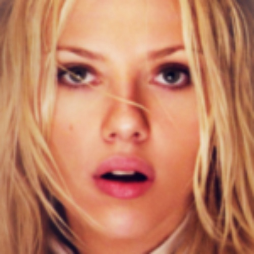
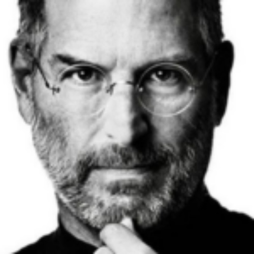
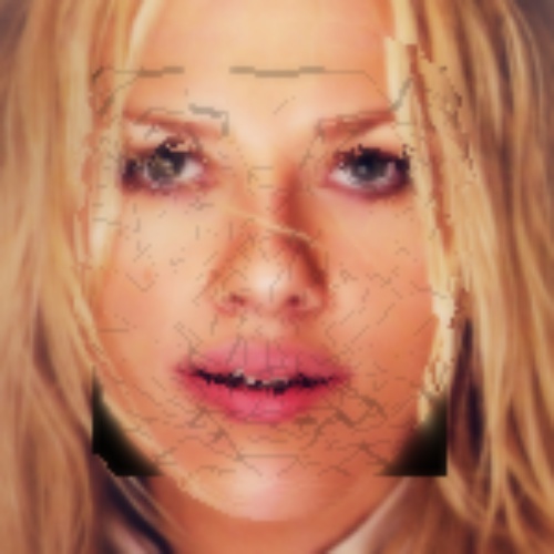
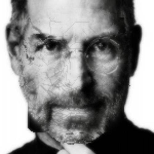
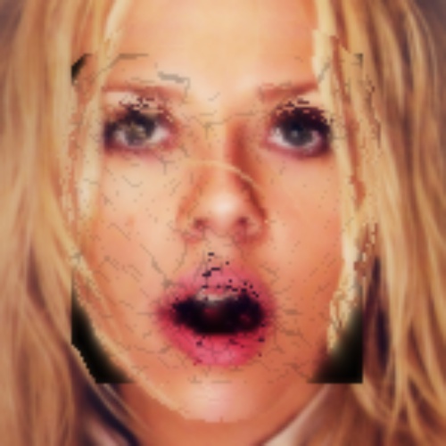
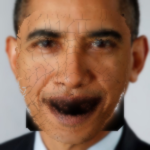
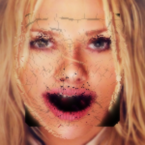
The most basic version of the program takes in 3 inputs: a source reference, target, and destination image. The source reference is an attempted imitation of the expression in the target image. Using this image makes defining correspondences much simpler--this image need not be perfect, but the closer the reference image is to the target, the better the result becomes. Here are some example inputs to the program:

|
|

|
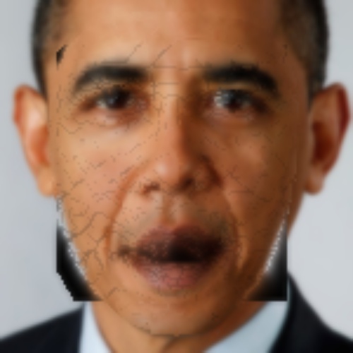
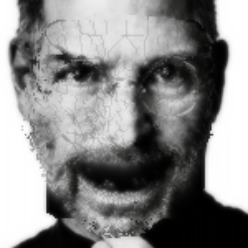
The goal here is to have Obama match the facial expression from the destination. In order to compare apples to apples, I used the dlib library to automatically extract square croppings of each face as shown below. We will use these to perform all further operations--this is the only information we will require.
|
Mesh Synthesis & Triangulation
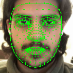
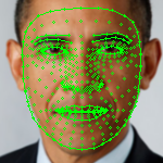
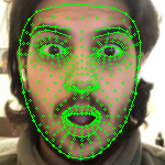
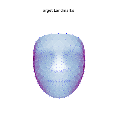
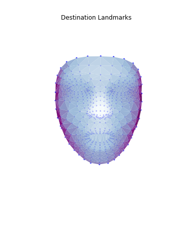
Like in project 3, our objective here is to morph the target face. However, the difference is that we will also have to deal with face orientations later on. As a result, we cannot use a 2d mesh as we did in the face morphing project. We must perform similar affine and translation operations (which will be discussed in more depth later on) which will match our destination expression. We begin by estimating a 3d set of facial landmarks. For the purposes of this project, I have used Google's MediaPipe FaceMesh to extract the landmarks. The landmarks are normalized, 3d coordinates.
|
|
|
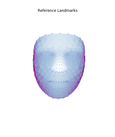
Then, I used these landmarks in combination with a Delaunay triangulation in order to generate 3d face meshes for each image. Since a Delaunay triangulation in 3d results in a tetrahedralization, I only used the x & y coordinates to generate the pattern, then added the z dimension in afterwards. The resulting meshes are shown below.
|
|
|
|
|
|
Once this was constructed, we are ready to attempt deformation & expression transfer.
Deformation Transfer
The math in this part was based on the research paper "Deformation Transfer for Triangle Meshes" by Robert W. Sumner and Jovan Popovic.
In the deformation transfer, our goal is to figure out the relationship between the reference & destination, so we can later apply a similar relationship to the target to match the expression. We model our transformation as an affine transformation $Q$ and a translation $d$. Each vertex of a given triangle $v_i = \begin{bmatrix} v_{ix} \\ v_{iy} \\ v_{iz} \end{bmatrix}$ of the source face mesh is mapped to the destination using these two parameters. That is,
$Qv_i + d = \tilde{v_i} \space\space\space$ (Eq. 1)
There exist 3 vertices for each triangle: $v_1, v_2, v_3$. However, in order to eliminate the $d$ term to solve for $Q$, we introduce a fourth vertex $v4$ which is perpendicular to the mesh. It can be computed using this formula:
$v_4 = v_1 + \dfrac{(v_2 - v_1) \times (v_3 - v_1)}{\sqrt{|| (v_2 - v_1) \times (v_3 - v_1) ||_2}} \space\space\space$ (Eq. 2)
We now have 4 equations to use for Eq. 1:
$Qv_1 + d = \tilde{v_1}$
...
$Qv_4 + d = \tilde{v_4}$
If we subtract the last equation from the statement above from every other equation, we have a system of 3 equations that do not depend on the $d$ term.
$Qv_i = \tilde{v_i}, \space i \in {1...3}$
Written in matrix form,
$QV = \tilde{V} \space\space\space$ (Eq. 3)
where
$V = \begin{bmatrix} v_1 - v_4 & v_2 - v_4 & v_3 - v_4 \end{bmatrix}$
$\tilde{V} = \begin{bmatrix} \tilde{v_1} - \tilde{v_4} & \tilde{v_2} - \tilde{v_4} & \tilde{v_3} - \tilde{v_4} \end{bmatrix}$
We can now solve for $Q$, the affine transformation between the source reference and destination. Once we obtain $Q$, we can obtain $d$ since it is the only remaining unknown.
$Q = \tilde{V}V^{-1}$
The transformation applied to the reference source is shown below:
|
|
|
|
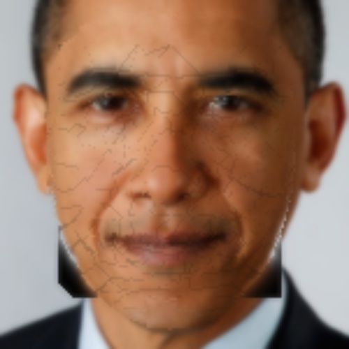
In theory, we should be able to apply this same transformation to the target mesh in order to replicate the facial expression. However, we run into an issue: while the facial expression is replicated, the mesh becomes fragmented because we did not enforce that triangles sharing vertices should have the same resulting points. Here is the result of applying the transformation computed above:
|
|
|
|
To fix this, we must set up an optimization problem where the resulting vertices remain connected. This will be in the form of a new affine transformation $T$ for each triangle in the target mesh. $T$ must be as similar as possible to $Q$ so that it captures the face shape transform, but needs to enforce connectivity of the face mesh. Our new objective is to find a matrix $T_{t_j}$ for each triangle $t_j$ that satisfies this.
We know that $T$ is a function of the transformed target mesh's points ($\tilde{V}$, unknown) and the original target mesh points ($V$, known). In a method similar to the way we set up $Q$, we set up an equation for $T$.
$T = \tilde{V}V^{-1}$
Let us also call the set of transformations that map our reference source triangles to the destination triangles ($Q$'s) $S$. Let $M$ be the number of triangles in our triangulation. We can now set up the following optimization problem:
$\min_{\tilde{v_1}... \tilde{v_n}} \sum_{j=1}^{M} || S_{s_j} - T_{t_j} ||^2_F \space\space\space$ (Eq.4)
In this optimization, we are trying to find the resulting set of vertices $\tilde{v_1} ... \tilde{v_n}$ that minimizes the difference between all reference source to destination transformations and target to destination. This will allow us to enforce connectivity of the transformed target mesh. Once we obtain T, we solve for the transformation. Note that the transformation will look less similar to the destination than the fragmented version--the optimizer finds the closest mesh using the face shape w The result is below:
|
|
|
|
While this mesh is smooth, I actually found better results using simply the fragmented mesh and interpolating the broken bits later on.
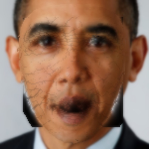
Expression Cloning
Now that we have obtained a well formed result mesh, we must apply it to the pixels in the original image. To do this, we simply project the 3d mesh into 2d, then perform an affine transformation to each triangle to replicate the expression with the target face shape. Then we interpolate the missing pixels in order to smooth out the transform. I used neighbor averaging to interpolate missing pixels, though this could certainly be improved in the future.

|
|
|
|
Awesome. We now have surprised people!
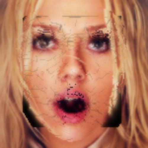
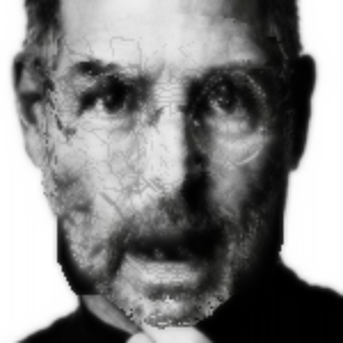
More examples
Here are examples of more expressions that have been cloned...

|
|
|
|

|
|
|
|

|
|
|
|

|
|
|
|
*** Note that the model for SMILE has no knowledge of the mouth interior, so it leaves a black space. There is room for improvement here: mouth estimation
Video Synthesis
With expression transfer, we can now piece together consecutive frames from videos to create fake live portraits! Here is an example with Obama:
|
|
|
Final Thoughts
Overall, I am pretty happy with how far I got! The results do reflect the sources, however, it is clear that they are synthesized and not real. In order to make this more realistic, there are several places for improvement:
- Perfect the fragmentation-free mesh transform (there are imperfections in the facial expression)
- Interpolate fragmented sections more cleanly
- Implement pupil tracking and inner mouth prediction for more realistic results
- Tune more with head turning as opposed to front on-views
I am sure there are many other ways to improve my result. I hope to continue working on this and improve it during break. Thanks for a great semester Professor Efros & Course Staff! I thoroughly enjoyed this course.
Sources
http://people.csail.mit.edu/sumner/research/deftransfer/Sumner2004DTF.pdf
http://groups.csail.mit.edu/graphics/pubs/thesis_sumner_121905.pdf
http://kucg.korea.ac.kr/seminar/2001/src/PA-01-49.pdf
https://graphics.stanford.edu/~niessner/papers/2015/10face/thies2015realtime.pdf
http://niessnerlab.org/papers/2016/1facetoface/thies2016face.pdf#page=9&zoom=100,66,221
http://niessnerlab.org/projects/thies2016face.html
https://google.github.io/mediapipe/solutions/face_mesh.html