Overview
In this project, I create a mosiac from multiple images to a base image. I also rectify images to make them straight up. This involves creating homographies and converting between them.
Shooting the Pictures
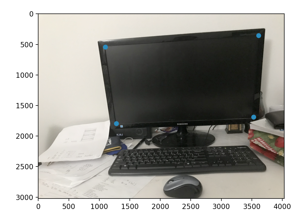
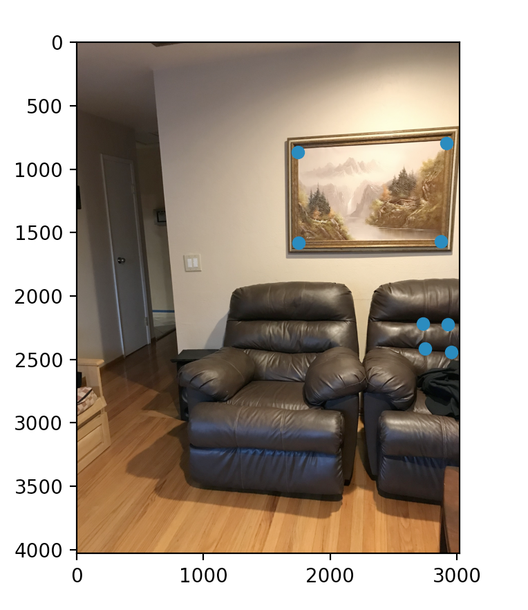
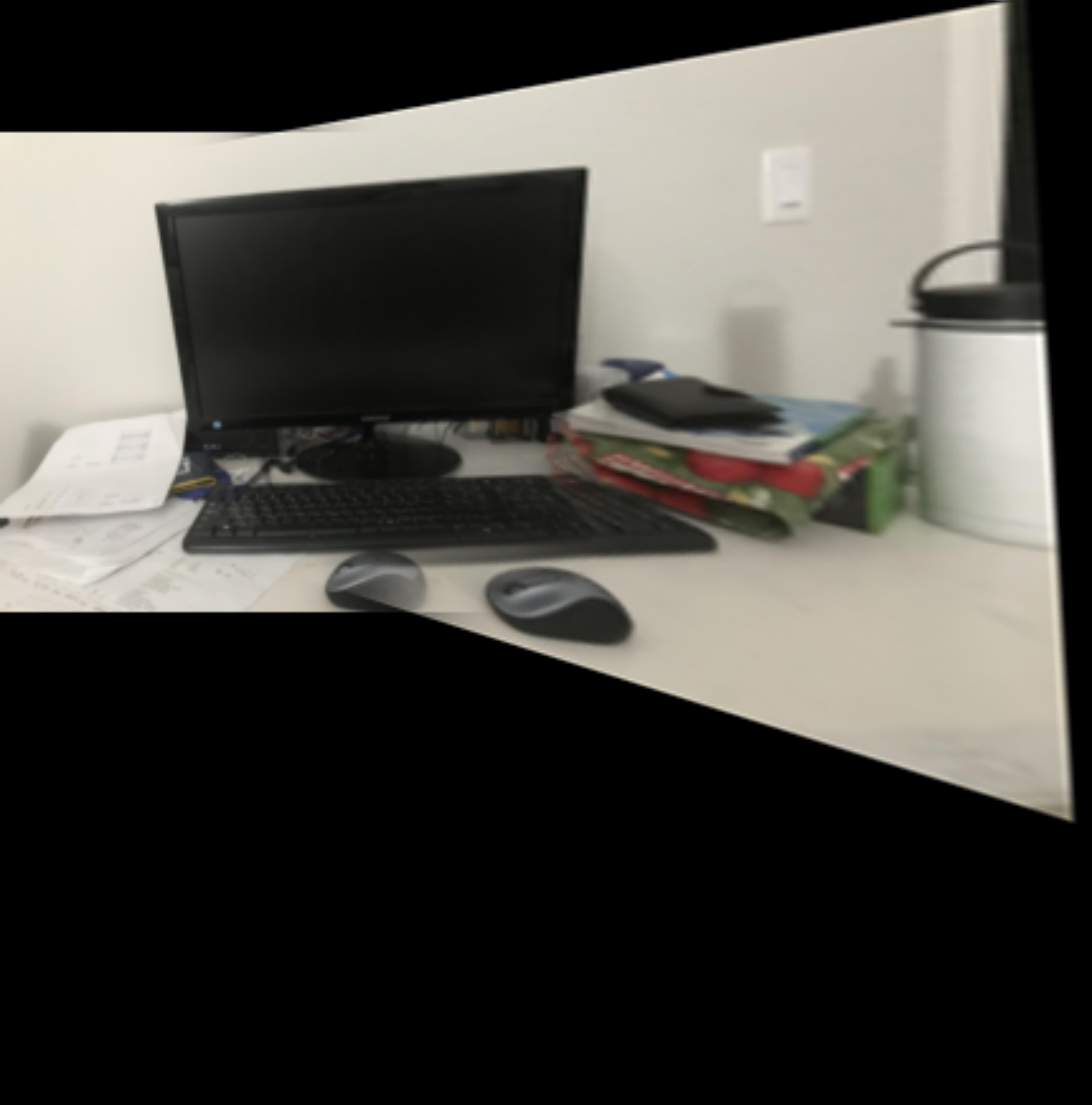
To define correspondences between two images, I selected easy to see points in the following 2 images. All these images describe a single plane.
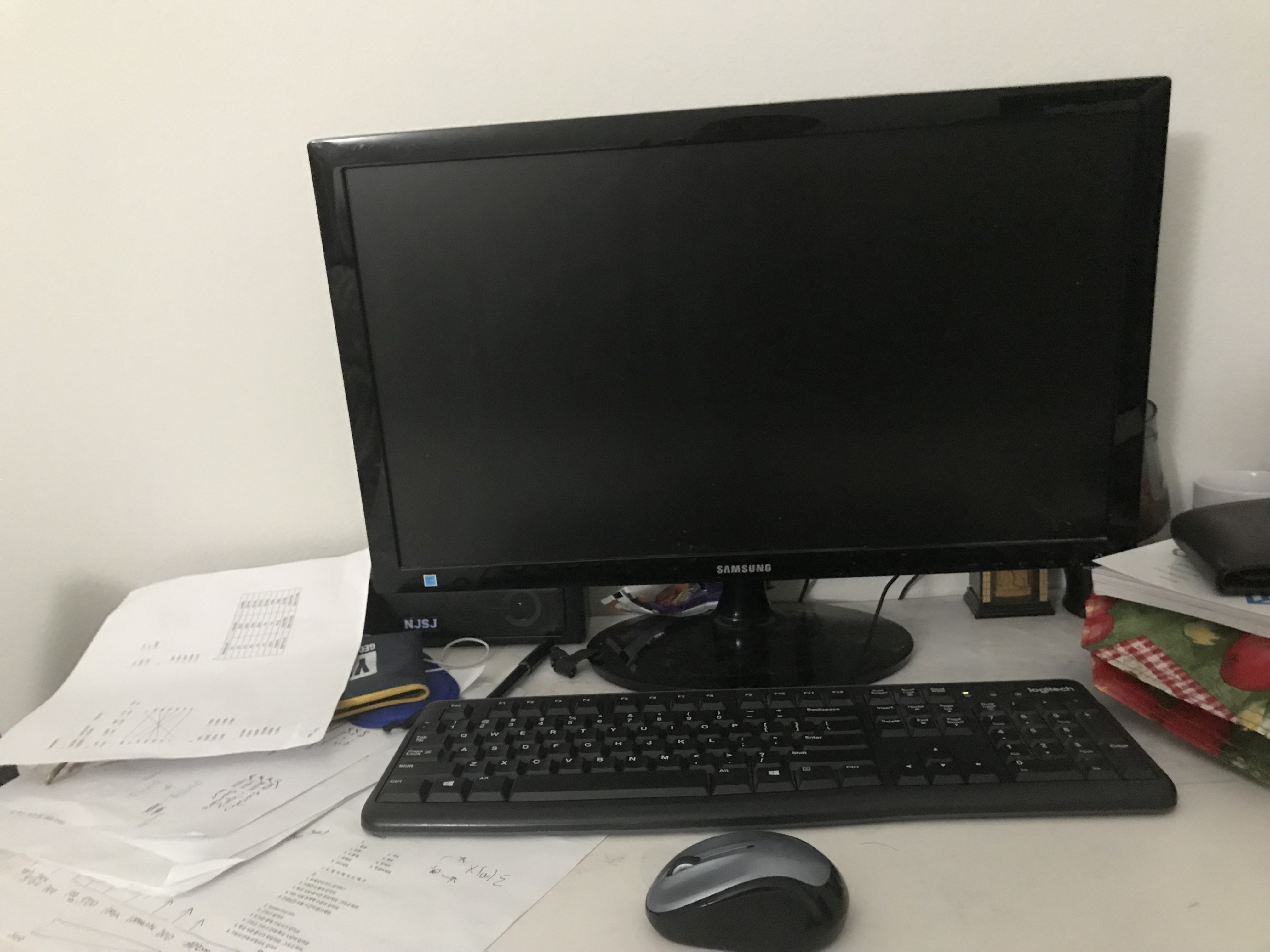 Laptop image left side. With the inside monitor being the four coordinates chosen
|
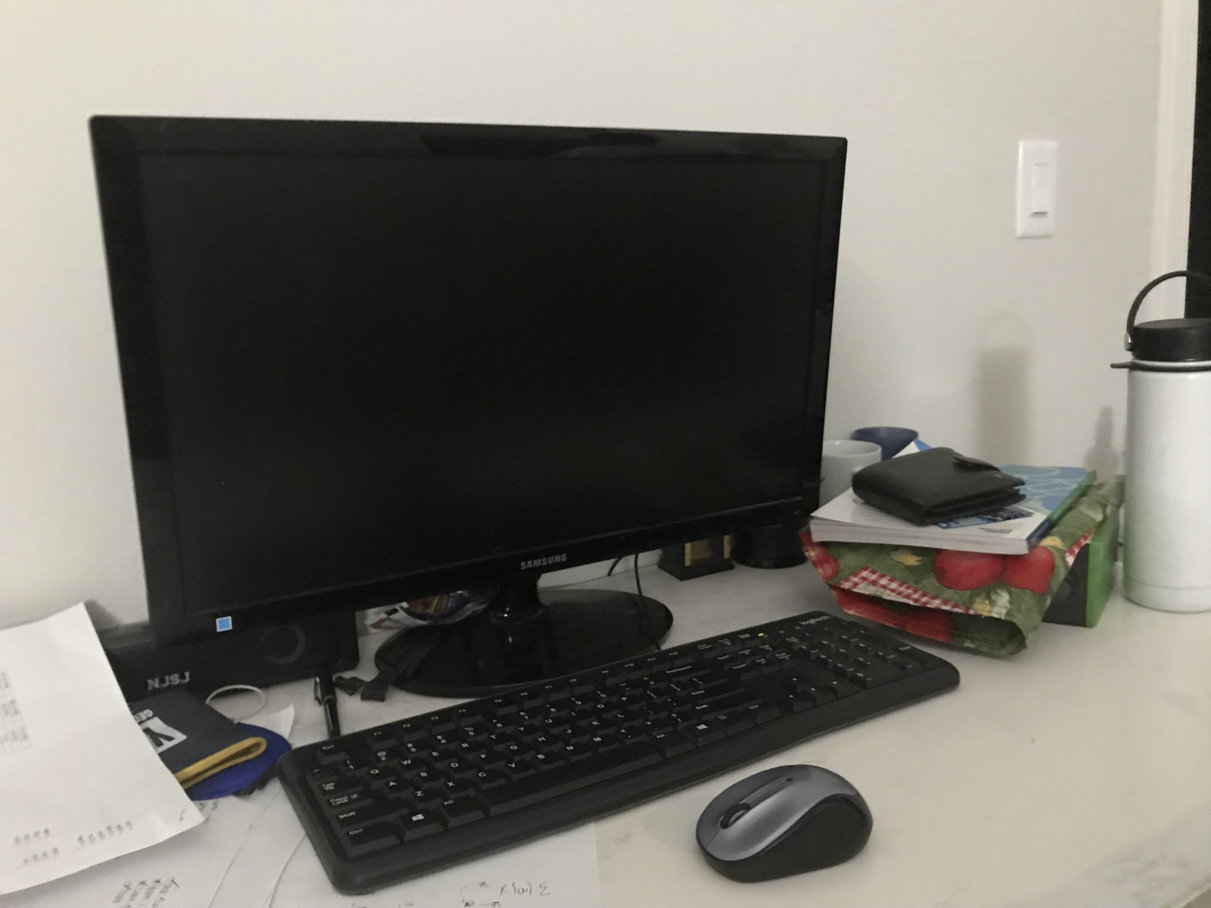 Laptop right. With the inside monitor being the four coordinates chosen
|
 Laptop image left side. With the inside monitor being the four coordinates chosen
|
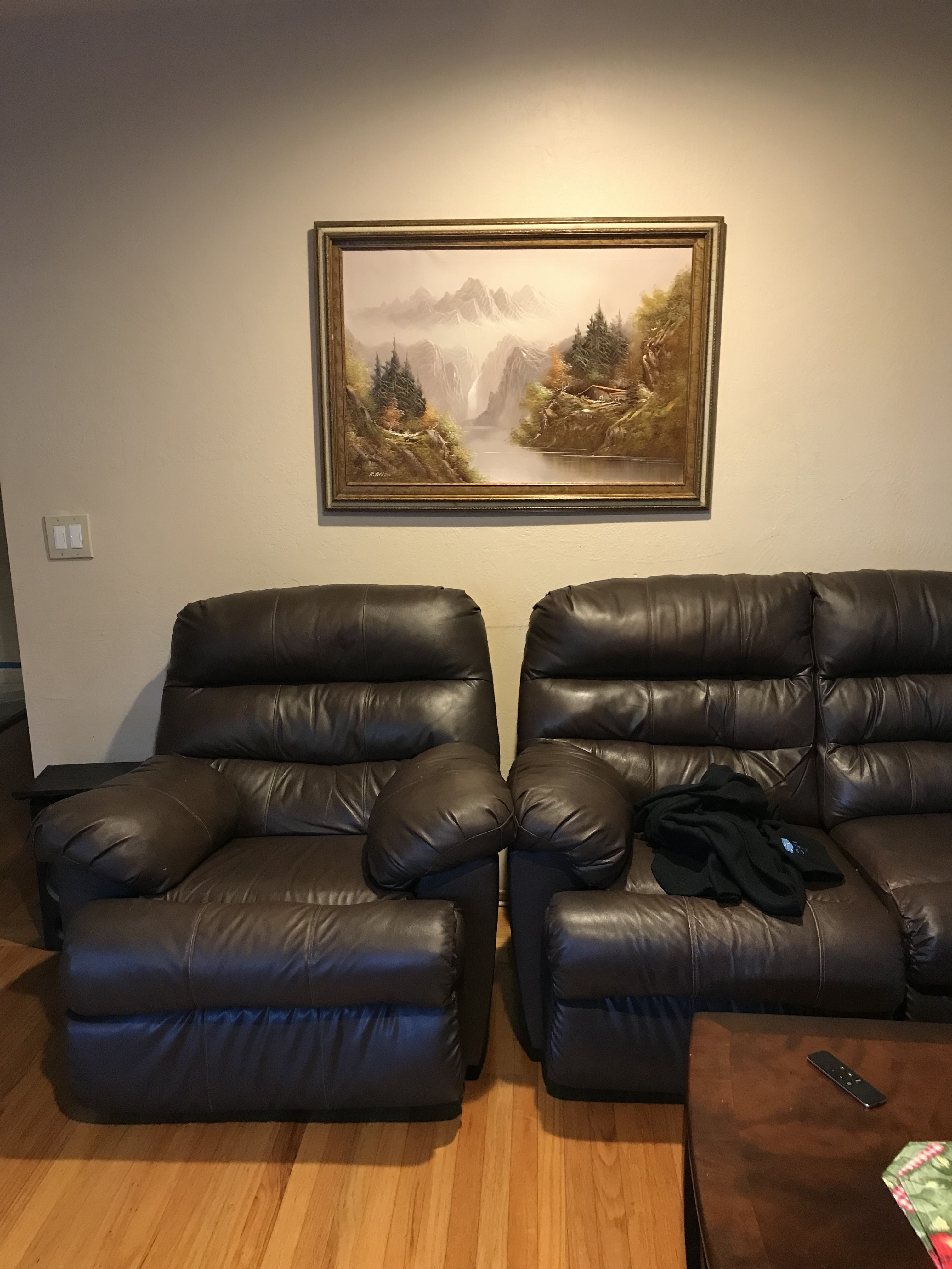
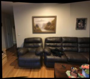
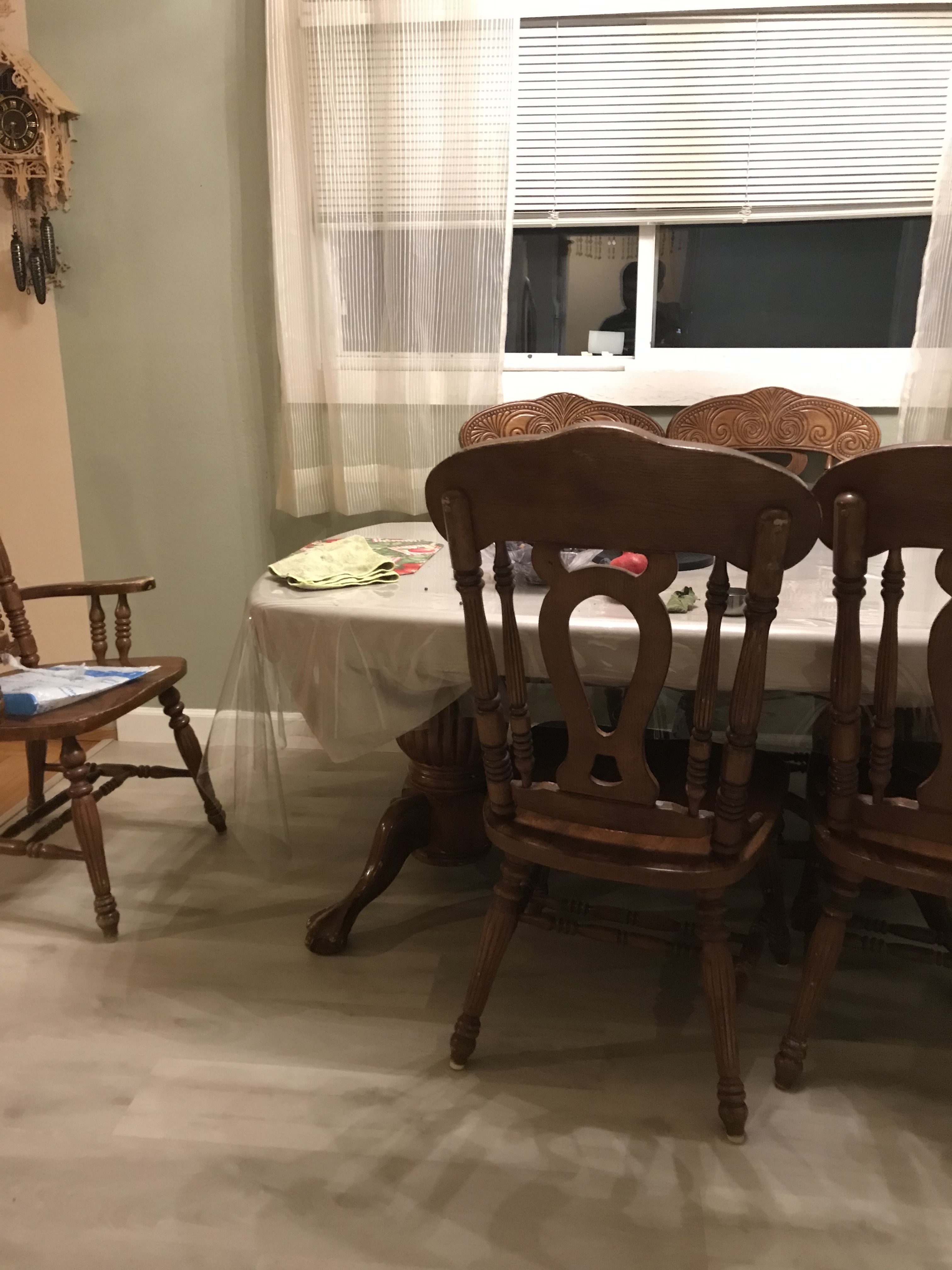
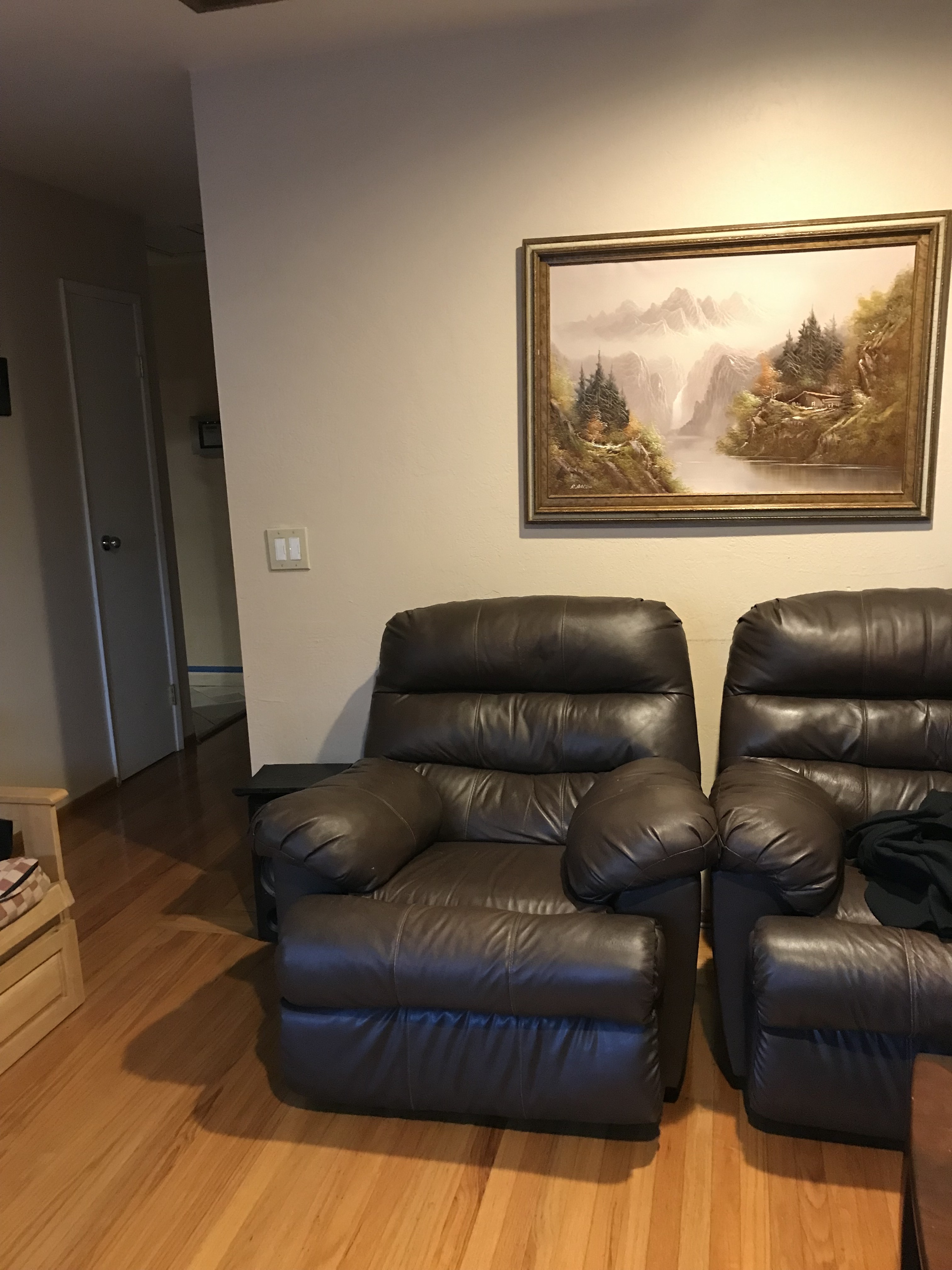 left chair with painting and chair as points
|
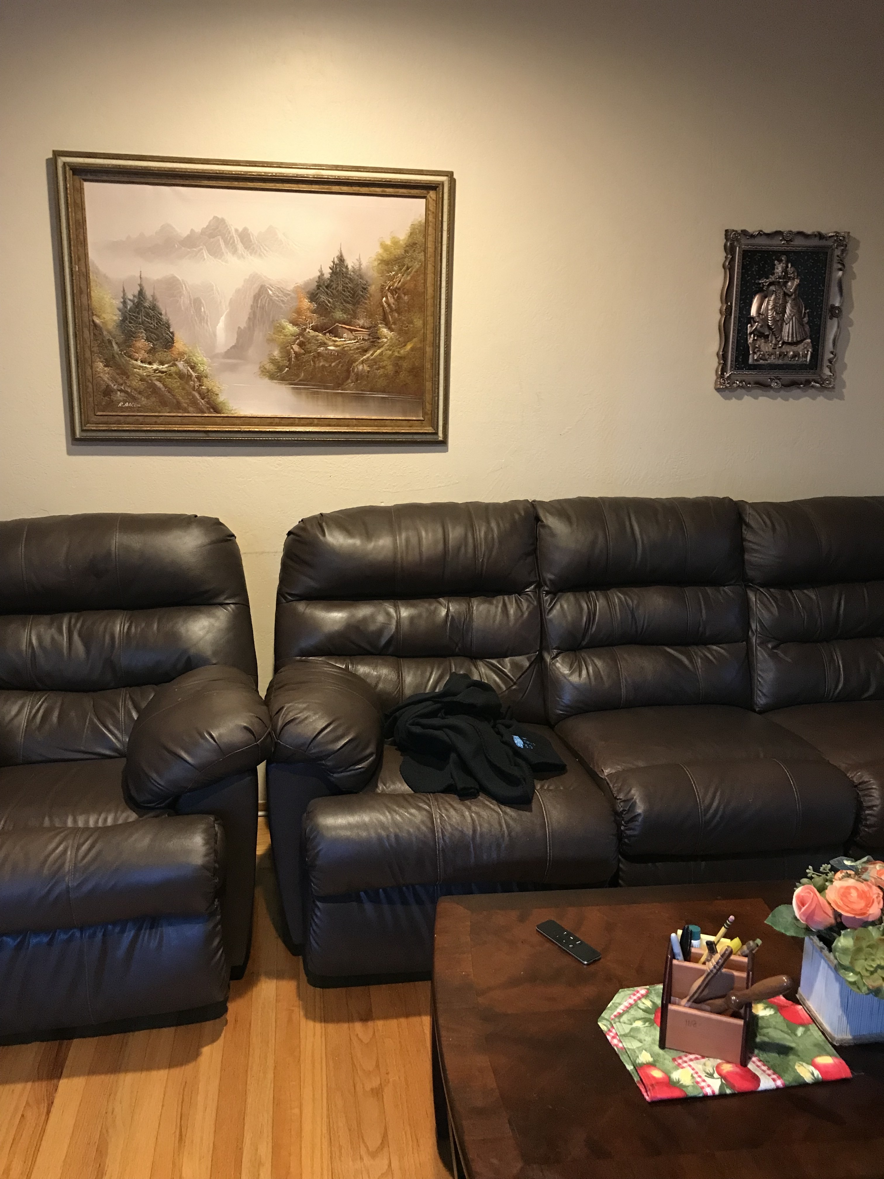
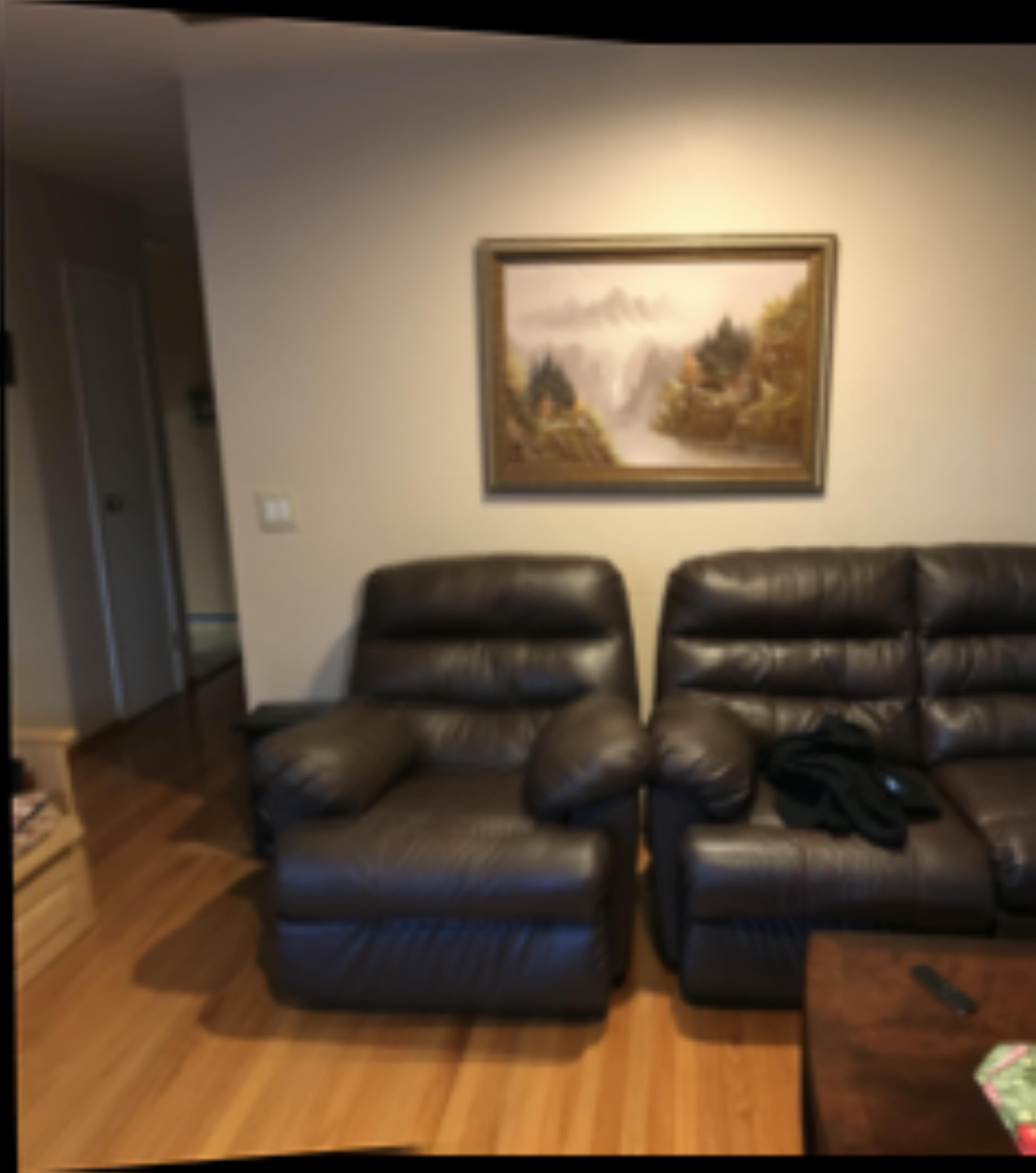
 center chair with painting and chair as points
|
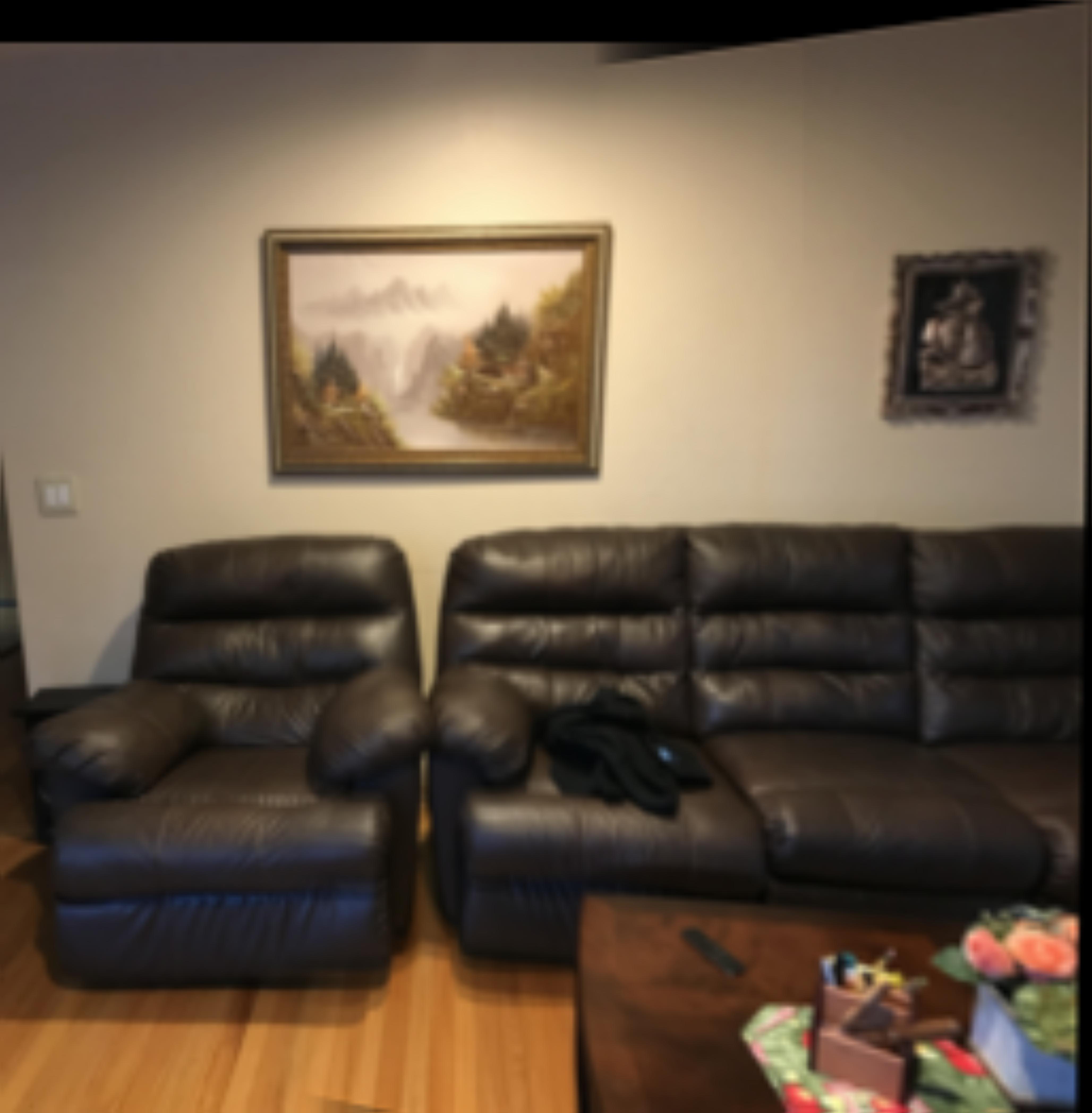
 right chair with painting and chair as points
|
 left chair with painting and chair as points
|
Recovering Homography
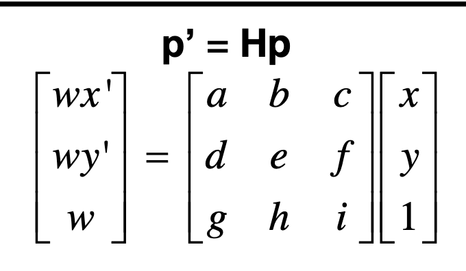
In order to recover the homography, I took the points from the two images and then computed the homographic transform.
The regular homographic transform between two sets of points is
 Homography Image
|
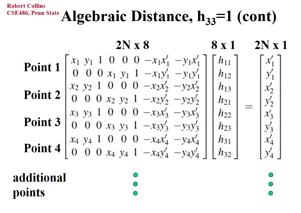
By setting the scale paramater i to 1, we can get the the equations (w = gx + hy + i). Plugging this into the other matrix, we getting the following larger matrix,
I created the following grid:
 Homography Image
|
We find this grid by setting the scale factor to 1 and unrolling the homographic transformation matrix in lecture.
This grid represents a transformation from image1's space to image2's space. This transformation is non affine. I generalized this code to accept arbitary number of x and y points. This made an overconstrained matrix that can be solved via least squares approximation.
Warping the Images
In order to warp the images, first the mosiac border needs to be computed. This can be computed by computing by computing the homography of the corners of the image. This is then put into the new larger space. This space might be bigger than the space of our images, so we need to adjust the size to be max(transformation) - min(transformation). Since we might have negative values after transformation(less than 0), we can compute a affine translation to make it so that points are algined with the new size.
With the translation, we can apply an affine transformation on the homography matrix to have it return values in the right order. I also compute the inverse to go from this homography space back to the original space.
To get the points in the new space, I create a meshgrid of all the points and apply the homography. Then, I remap them them cubic interpolation into the true mosiac's size.
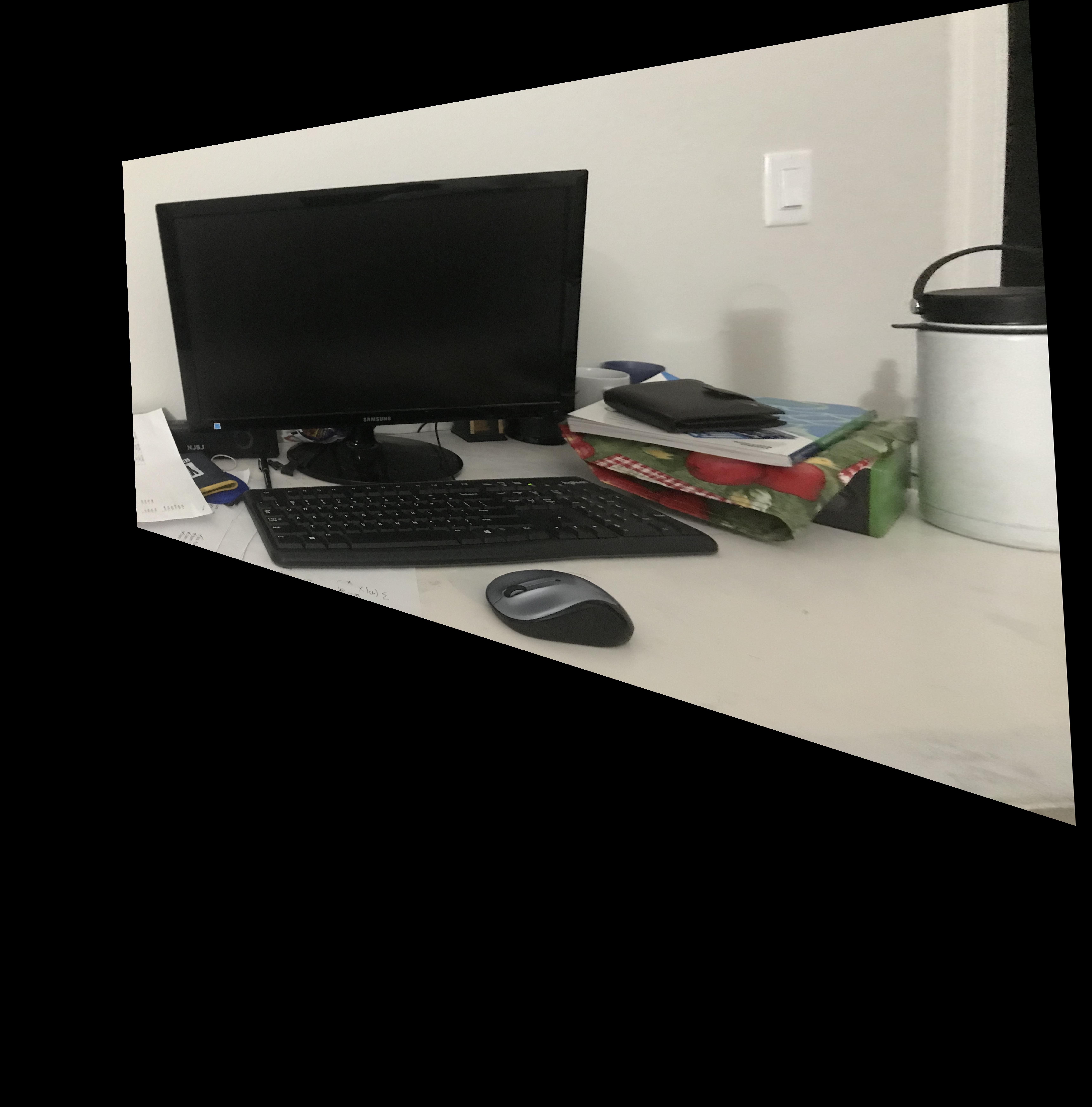 Just one warp of the image
|
Rectify Image
Rectifying the image was very similar to the warping of the image. This time, after the 4 points were selected, we computed a the leftmost corner and rightmost corner. We can then compute a rectangle using those four points.
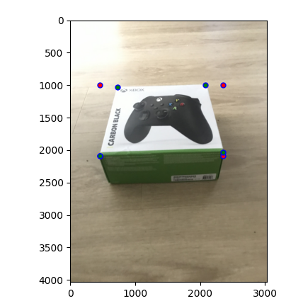 The red points are the new coordinates added to rectify.
|
.
Then, this can be run through the warping code to get the following results.
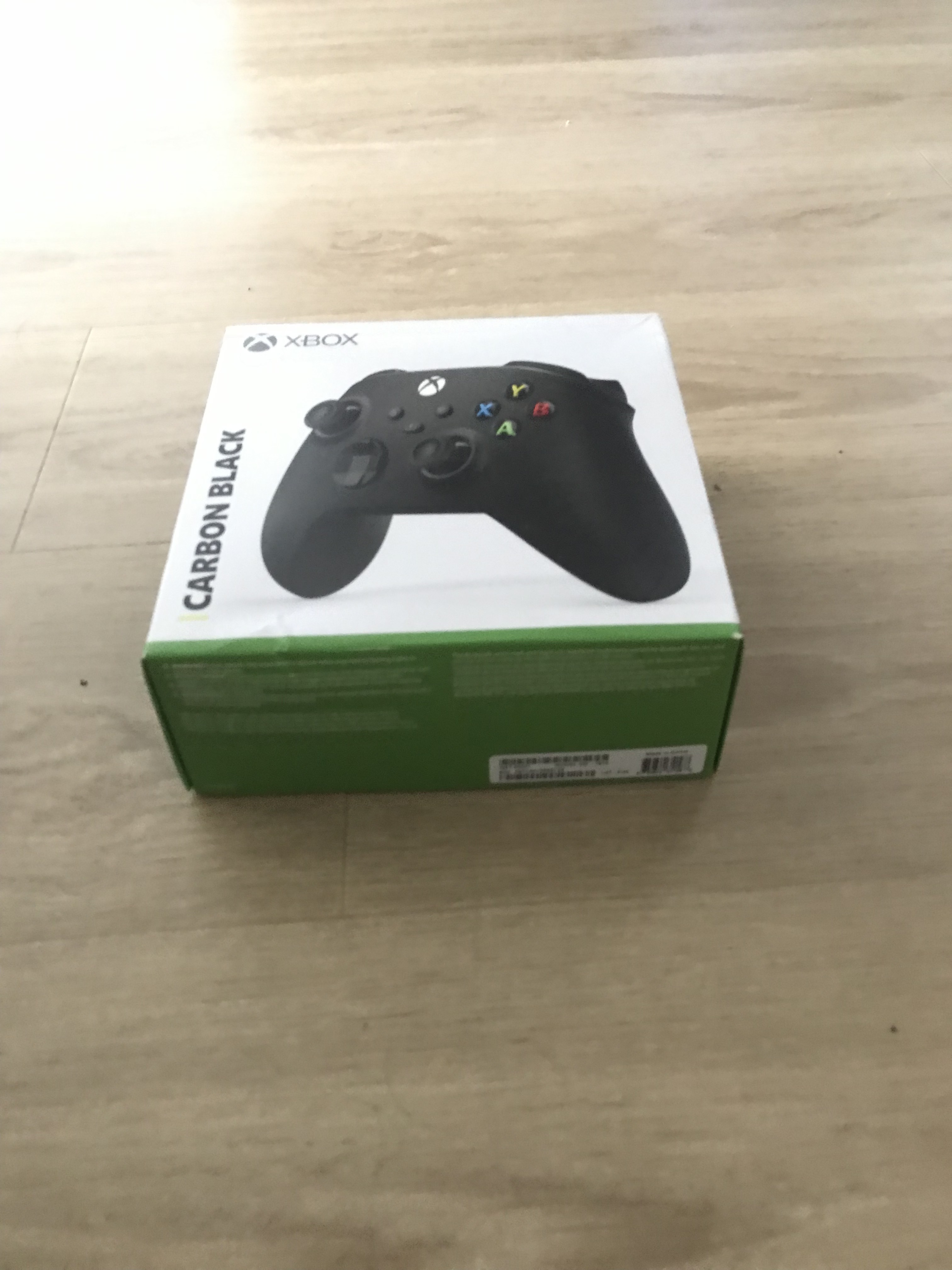 Image of xbox box before rectify
|
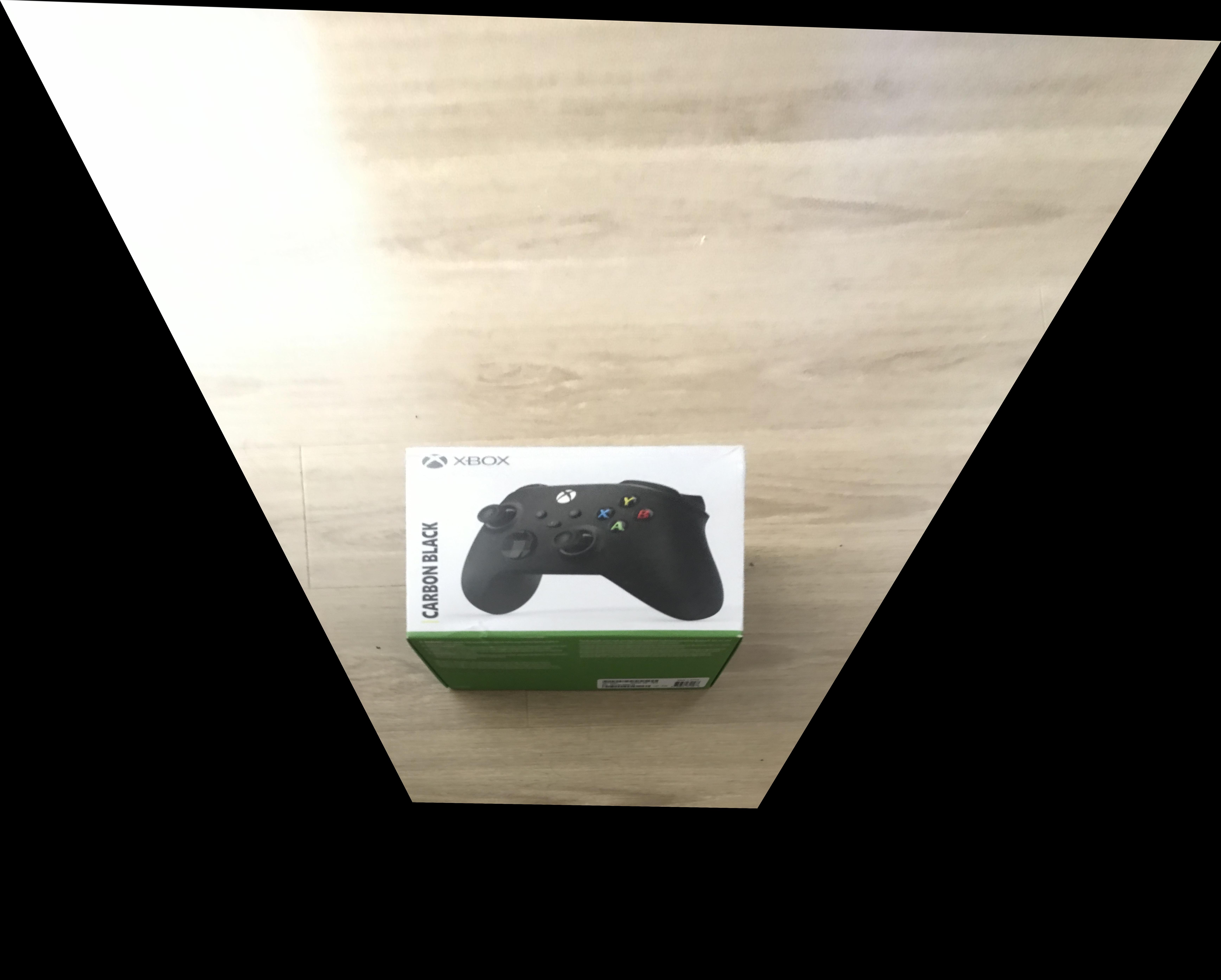 Image of xbox after rectify. It can seen that the image is straight up
|
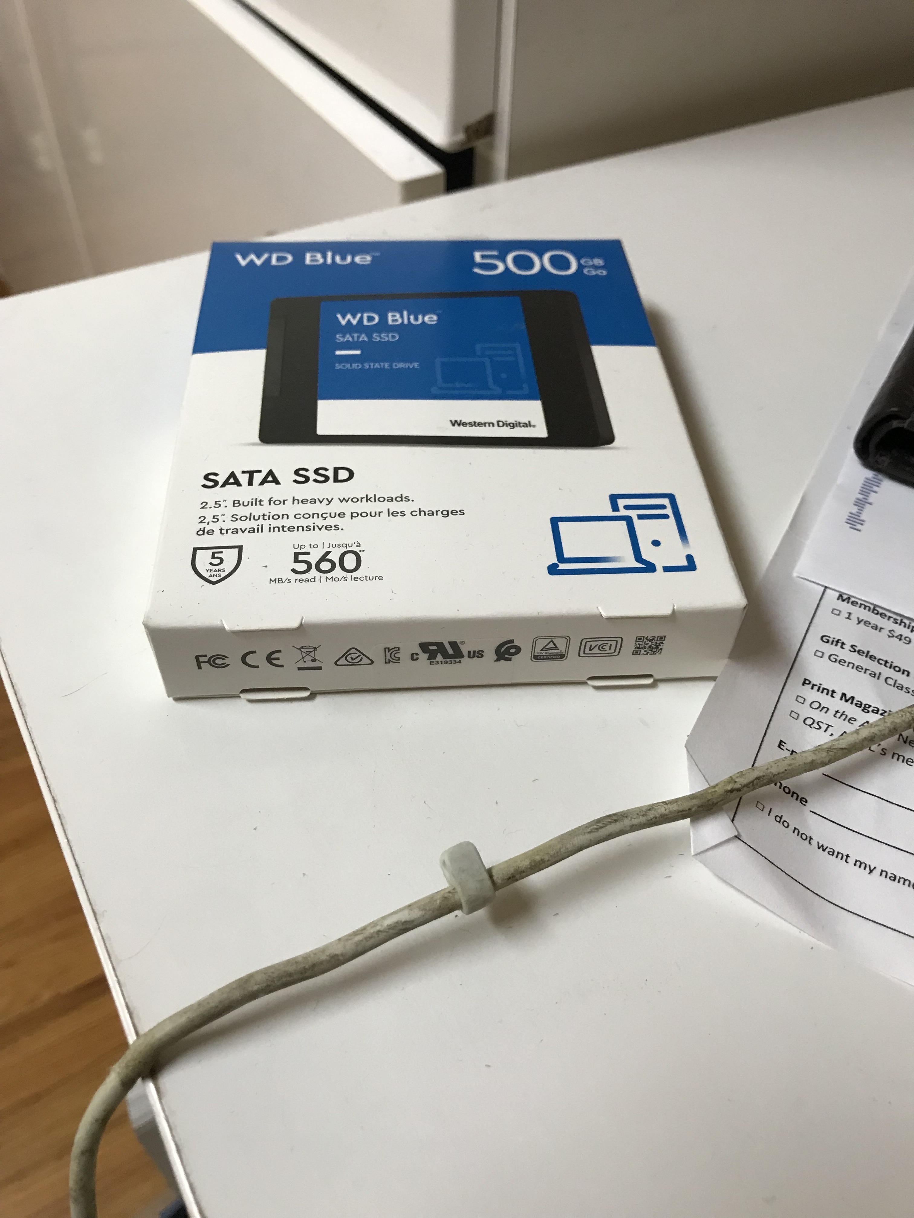 A ssd box pre rectify
|
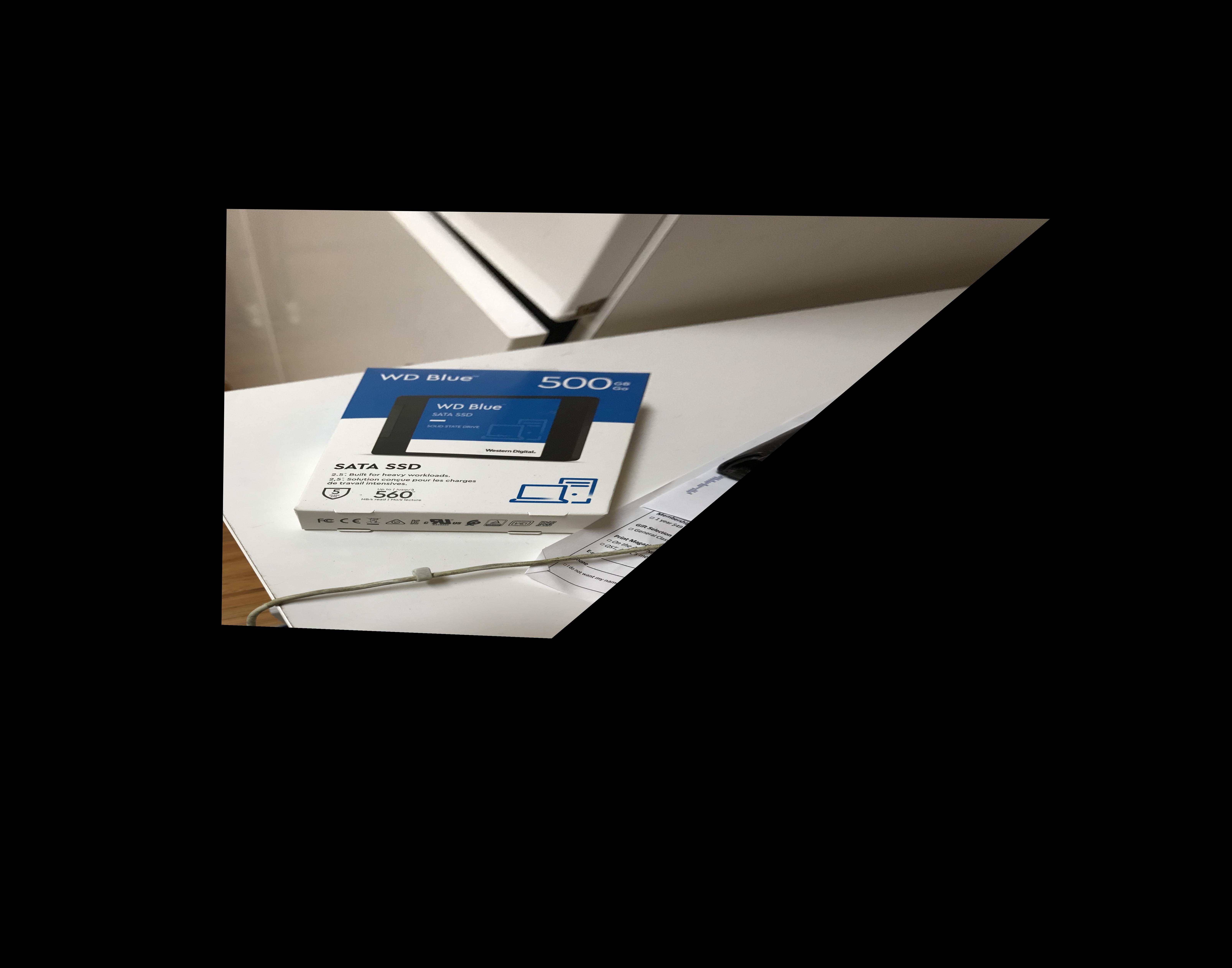 SSd box post rectify
|
.
Blending Image into a mosiac
In order to blend images into a mosiac, I just overlayed the warped image with the base image. However, this may create some sharp edges.
I created a custom process in order to produce a better blend.
First I compute mask where warp image is present, mask_a.
Then, I compute a mask_b where unwarped image is there. mask_c is the overlapping region with mask_a * mask_b.
I then compute the gaussian convolution to blur the edges for mask_a, mask_b, and mask_c. In order to reduce the overlapping region, I now subtract mask_a - mask_c and similarily with mask_b. This creates the areas that are not really overalapping with a and b but in a blurred form. Then, I compute a threshold mask of this white and black image to get the overlapped regions that is not covered by the gaussian. I blur this area with a weaker gaussian and add it to both masks. Then I multiply image a * mask_a + image * mask_b. Then, I divide by the 1/(mask_a + mask_b) to make the overlapping regions noramlized.
This process is a little confusiong, but the diagram below might help visualize what the masks are doing.
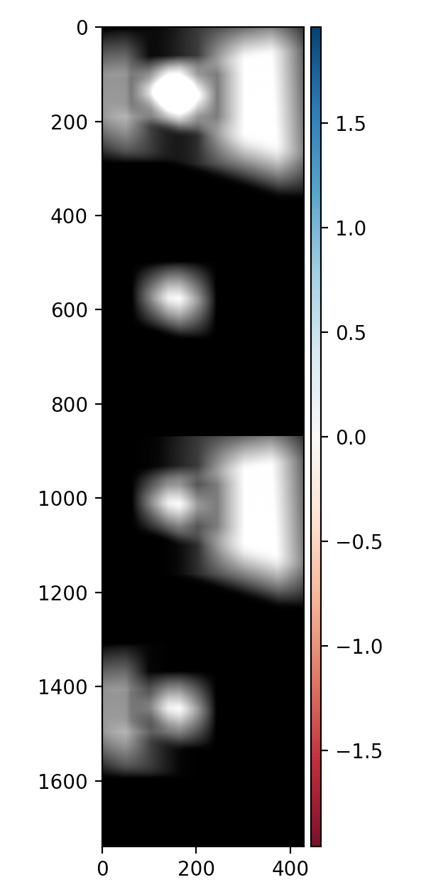 First image is mask_a + mask_b. Second image is thresholded overlapped blurred. Third is mask_a. fourth is mask_b
|
 Masks for this image
|
|
Laptop left
|
Laptop right
|
This process was convoluted but gave really good results when blurring the images.
To blend more than 2 images, I just computed the left mosiac and the then the right mosiac, then combined them together based on the offsets from the base. This can be done repeatedly.
 Complete Mosiac of my sofa
|
 Left sofa with center
|
 middle sofa with right
|
This is using the sofa images shown above.
The following is with a chairs at my house.
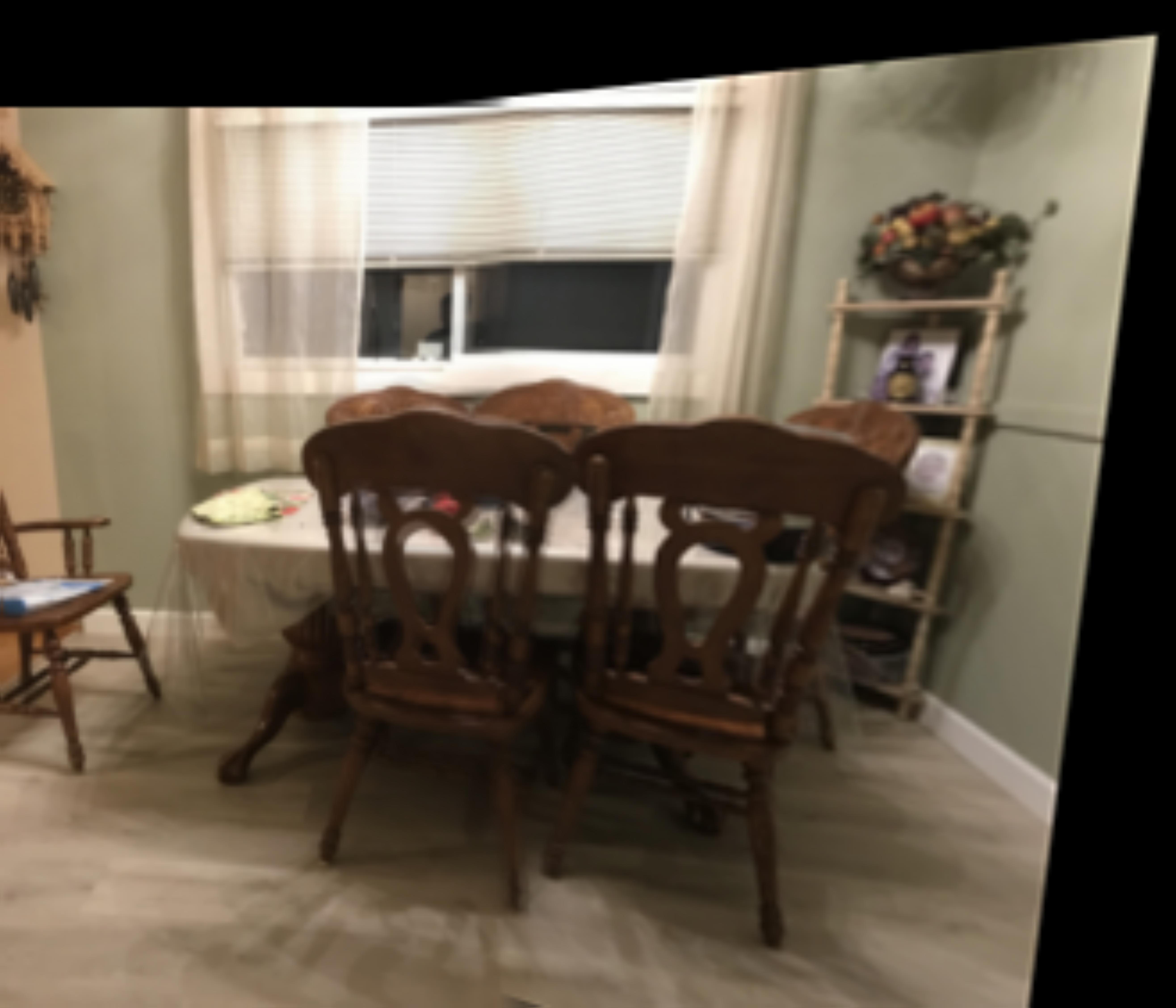 Complete Mosiac of my chairs
|
 Left image chair
|
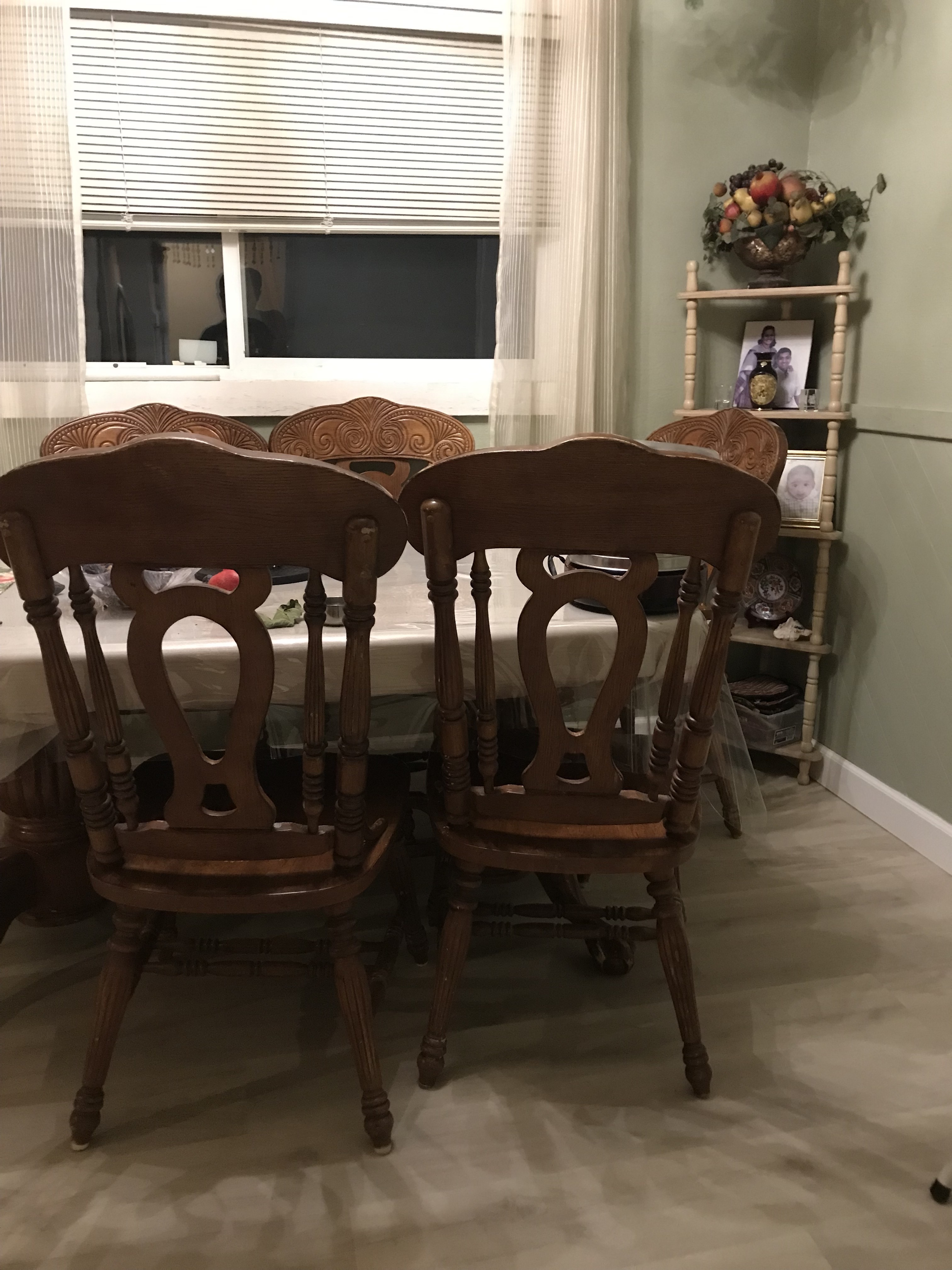 right image chair
|