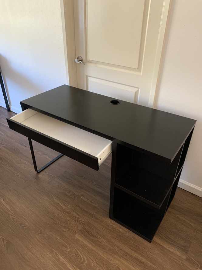
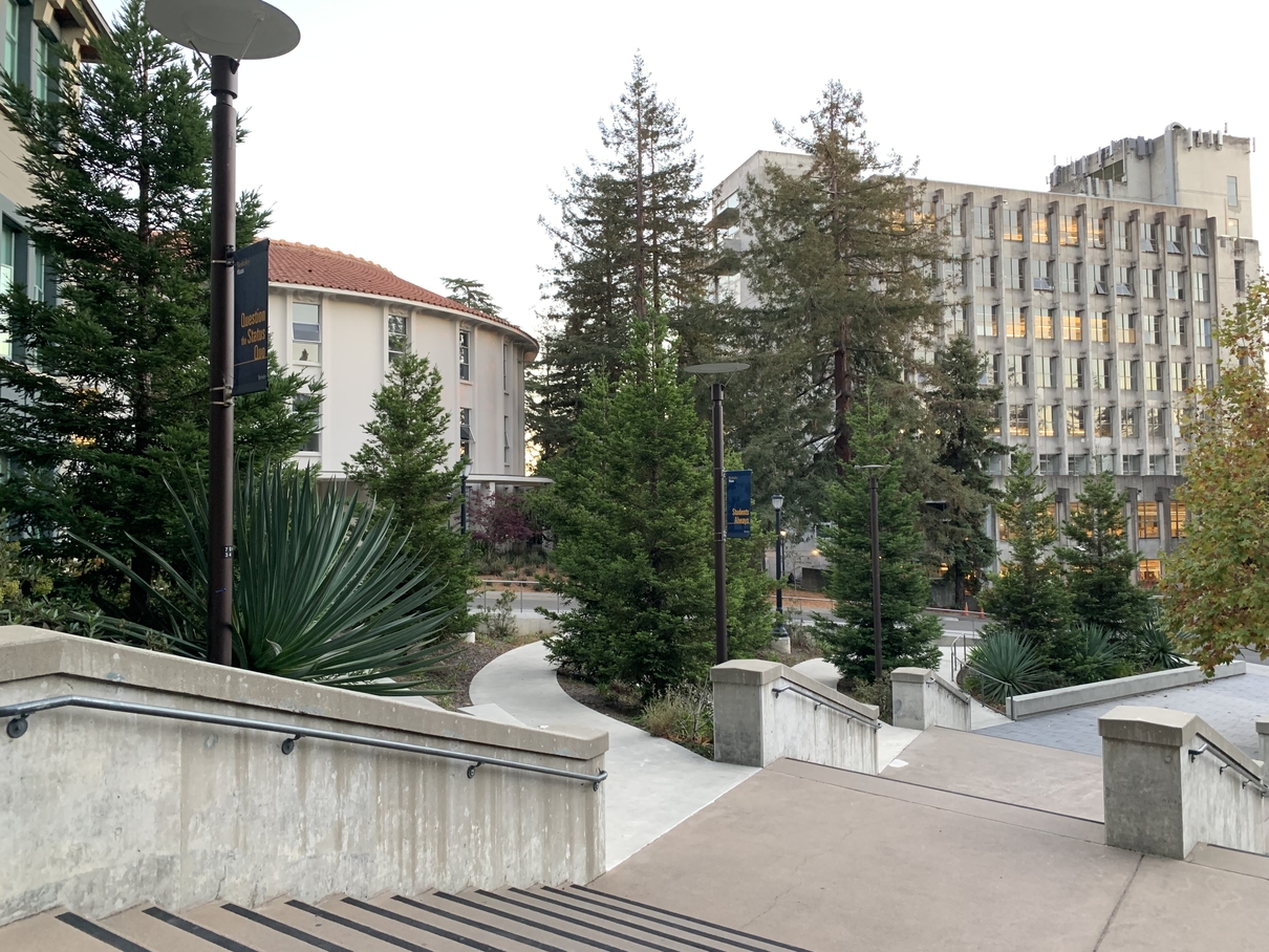
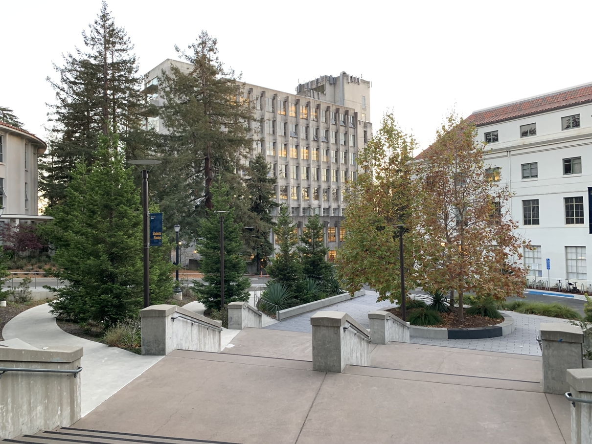
The first thing to do to start this project is to, of course, shoot the pictures. However, these pictures should not be taken casually. We must shoot them such that the transforms between them is projective. One way to do this is by shooting from the same place but in different directions. These photos must have a significant amount of overlap (around 40-70%). There are also many other things to keep track of like trying to take the photos close together in time, making sure the camera settings are consistent for each set of photos, etc. This is what I decided to do for my mosaics, which you will see shortly. Here is an example of a set of two images that I turned into a mosaic.
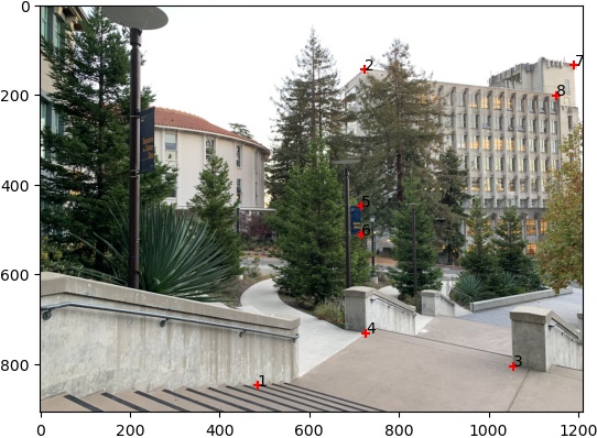
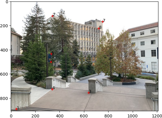
To recover the parameters of the transformation between each successive pair of images, we must define corresponding points between each one. Here is an example of a pair.
The next step is to actually calculate the parameters of the transformation between each pair of images. For our purposes, this transformation is a homography which takes the general form of p' = Hp. The H is a matrix with 8 degrees of freedom and 1 scaling factor at the lower right corner, which can be set to 1. Here is the general form in more detail.
General Form
However, this is a little difficult to work with when it is used in code. With a little bit of linear algebra, we can convert the general form into the least squares form, which is much nicer to implement. Here it is for 4 pairs of corresponding points.
Least Squares Form
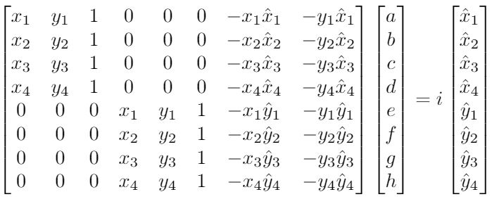
The system can be solved with a minimum of 4 correspondences. However, only having 4 is not ideal as the homography recovery will be very noisy and unstable. As such, it is recommended to have more than 4 correspondences to create an overdetermined system.
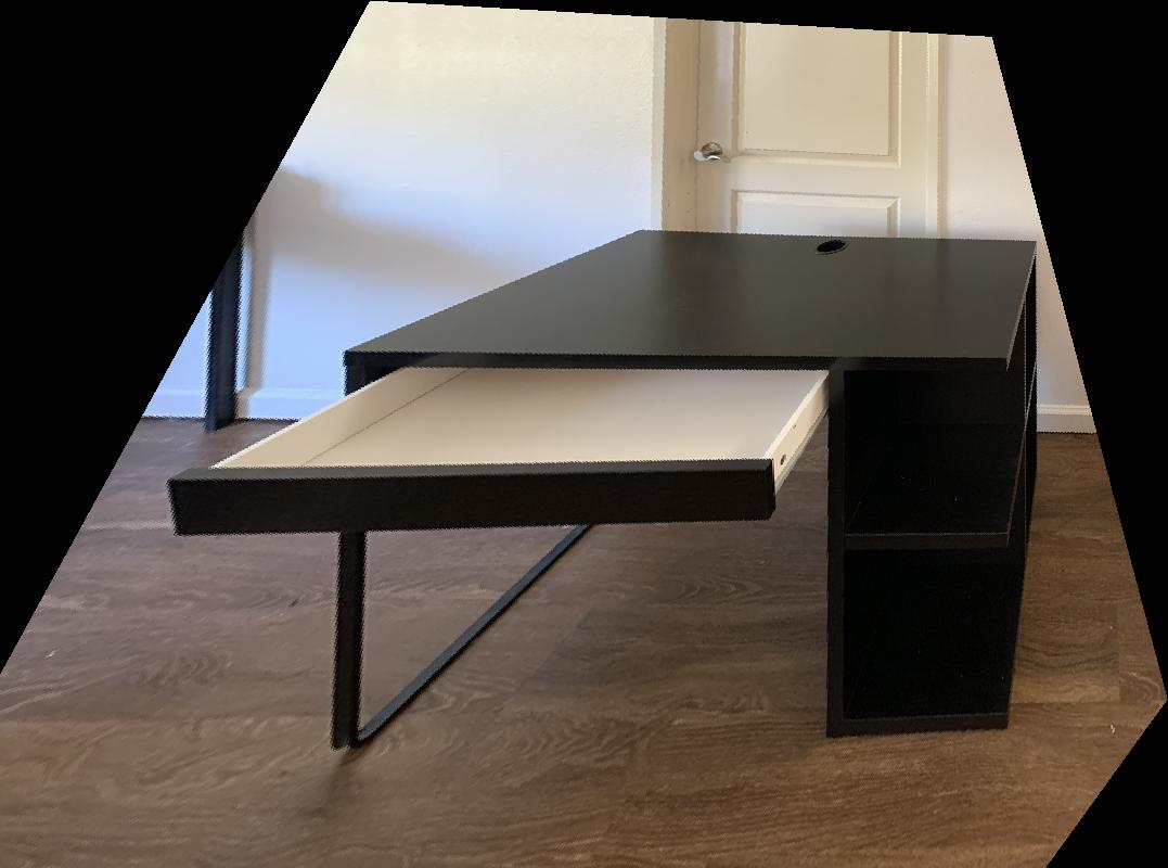
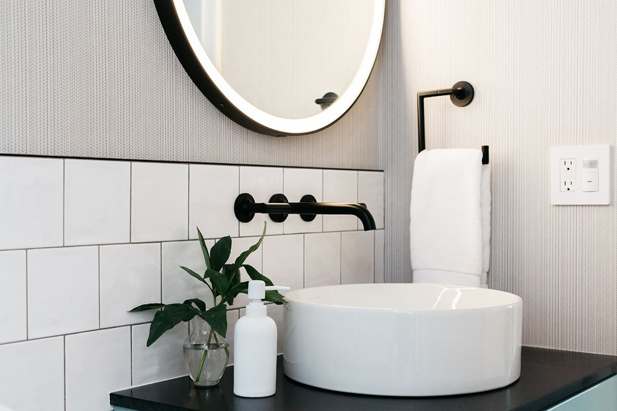
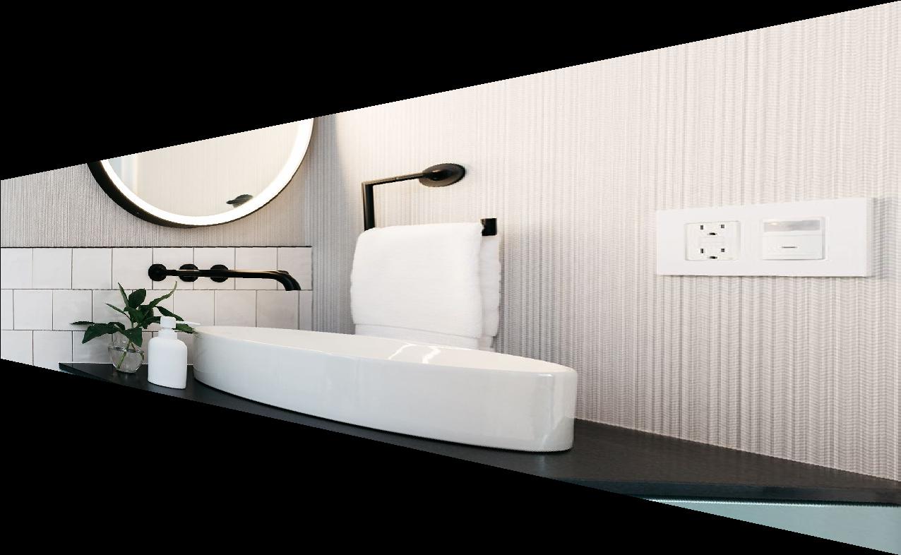
Now, we are ready to rectify or warp our images using the recovered homographies. The basic idea is to use forward warping to find the image's new coordinates in the basis of the image it is warping towards, and then inverse warping (and interpolation) to remap the appropriate colors from the old image to the new warped image. I have some examples of rectified images below. The first one is rectified such that the cube storages (or at least the front side) is facing directly towards us. Similarly, the second one is rectified such that the bathroom wall (where the faucet comes out from) is facing directly towards us.
Original
Rectified/Warped
Now, here comes the fun part! Once we have defined the correspondences between each
successive pair of images, recovered the homographies, and are able to warp images, we must
now find a way to put all the appropriate images together. One way to do this is to warp all
the images to one basis, which can be chosen through the basis of one image or some other
carefully selected one. If we have computed homographies for each successive pair of images,
how do we use those to warp the images to one basis? This could be done by simply composing
homographies! Remember that the homography parameters are defined within matrices, so it is
possible to do something like
         warp img2 to the basis of img1 with H21

         warp img3 to the basis of img1 with H31 = H32 @
        H21

         ...
Once you warp all the images to the appropriate basis, you must now blend them. This could be
done with weighted averaging. Basically, a pixel's value will hold 1/n of the
values from all the images that overlap it, where
n = number of images that overlap.
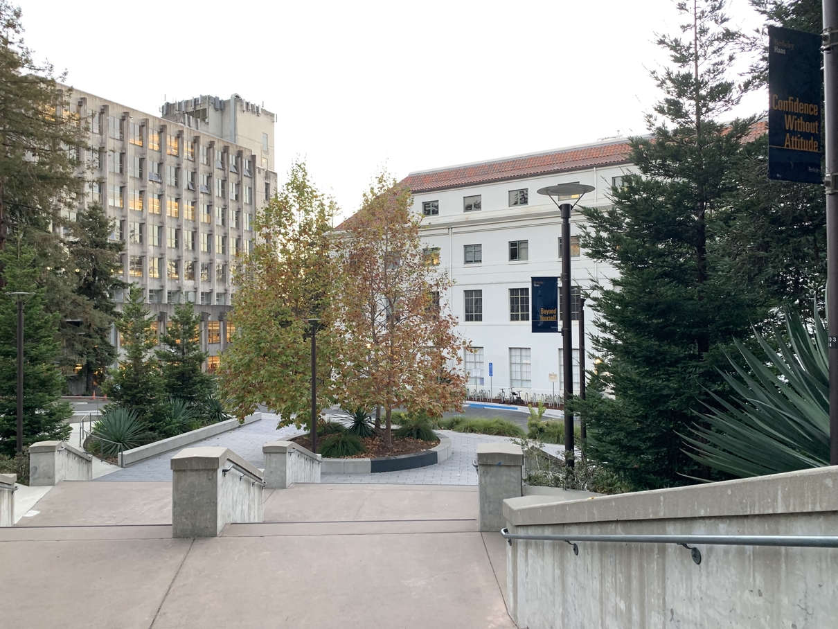
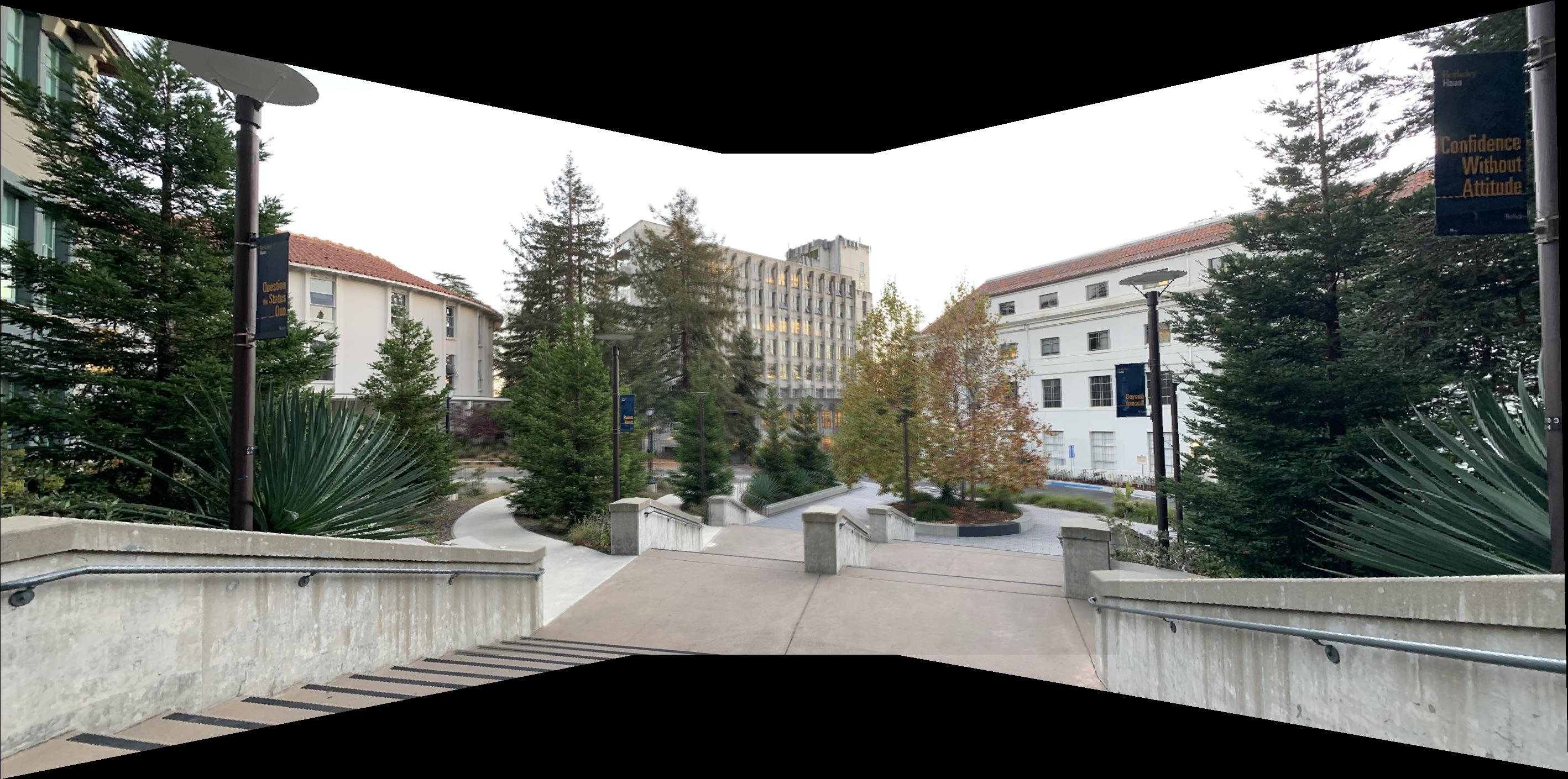
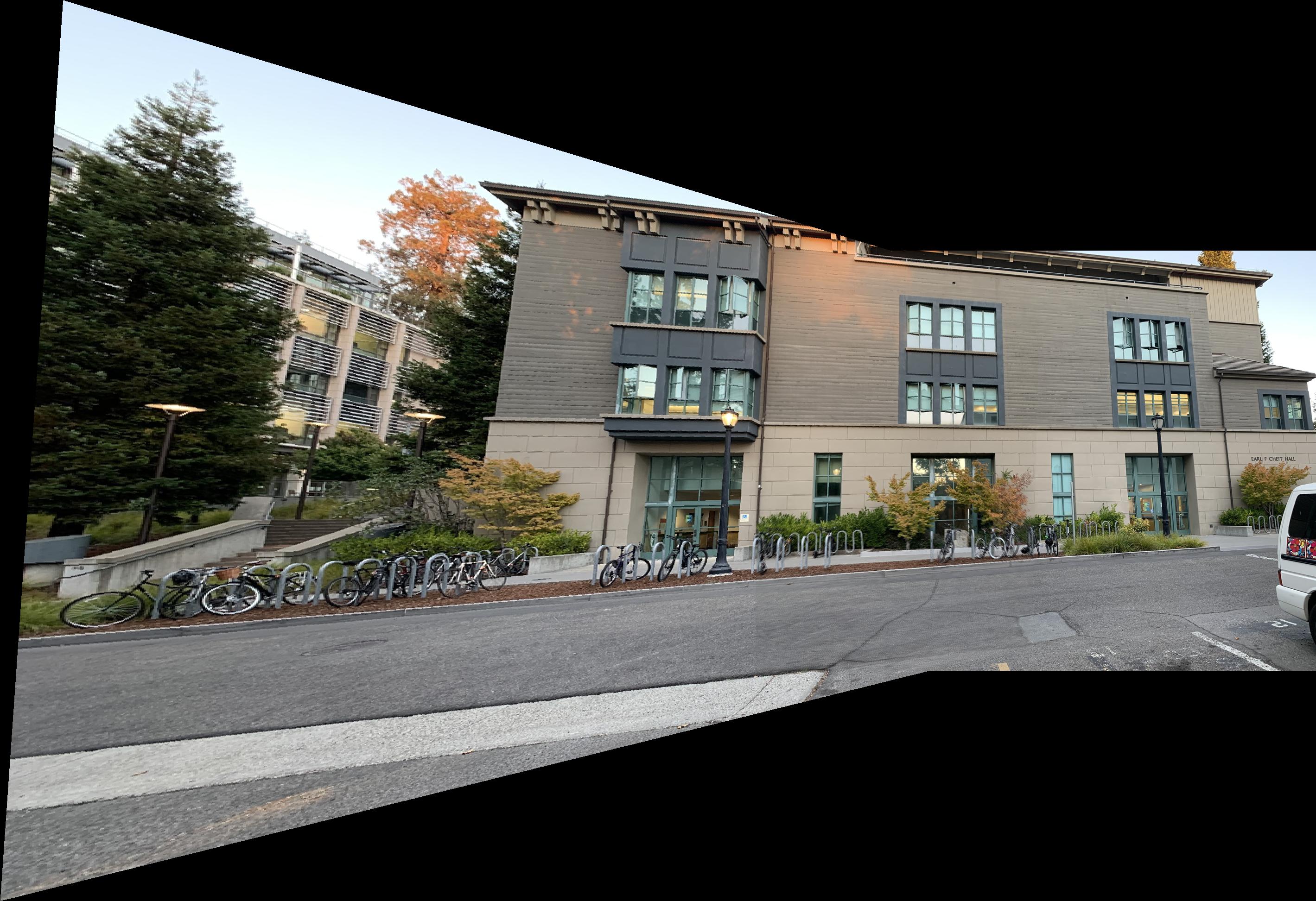
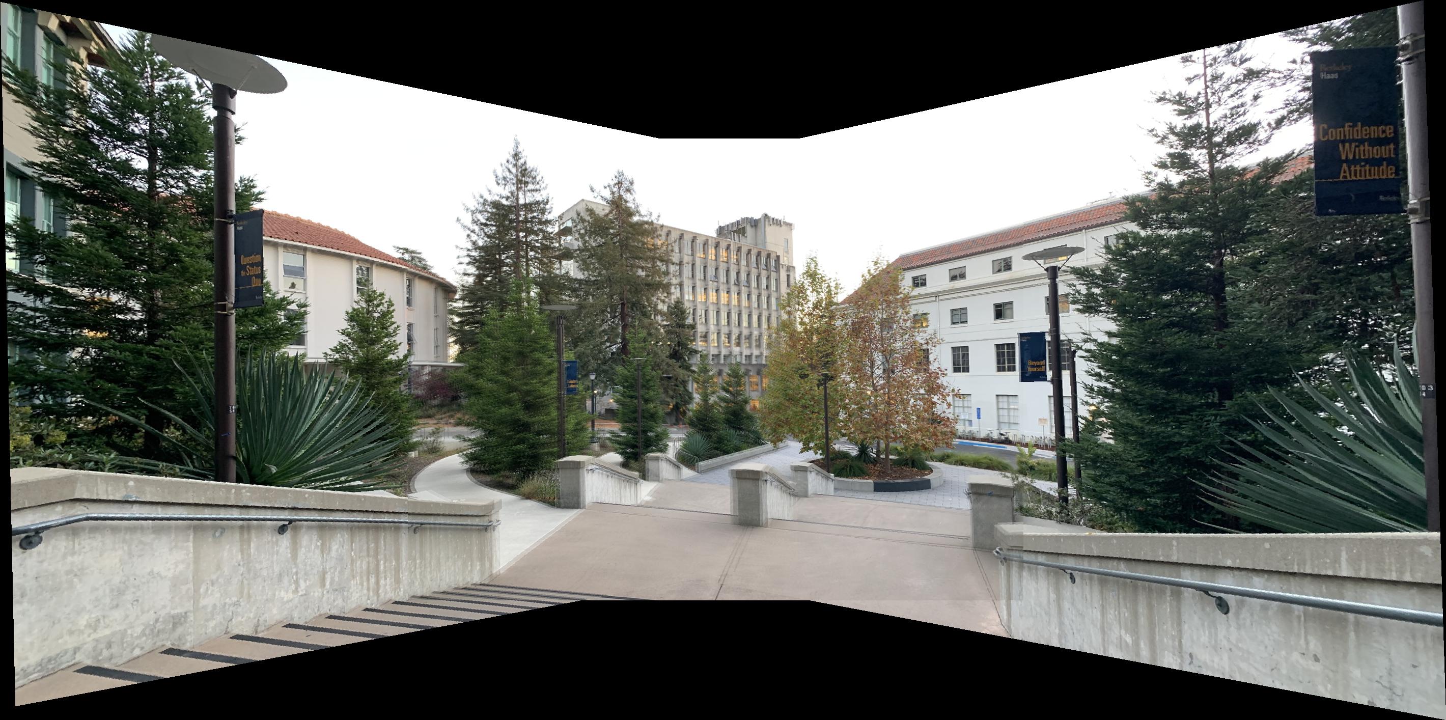
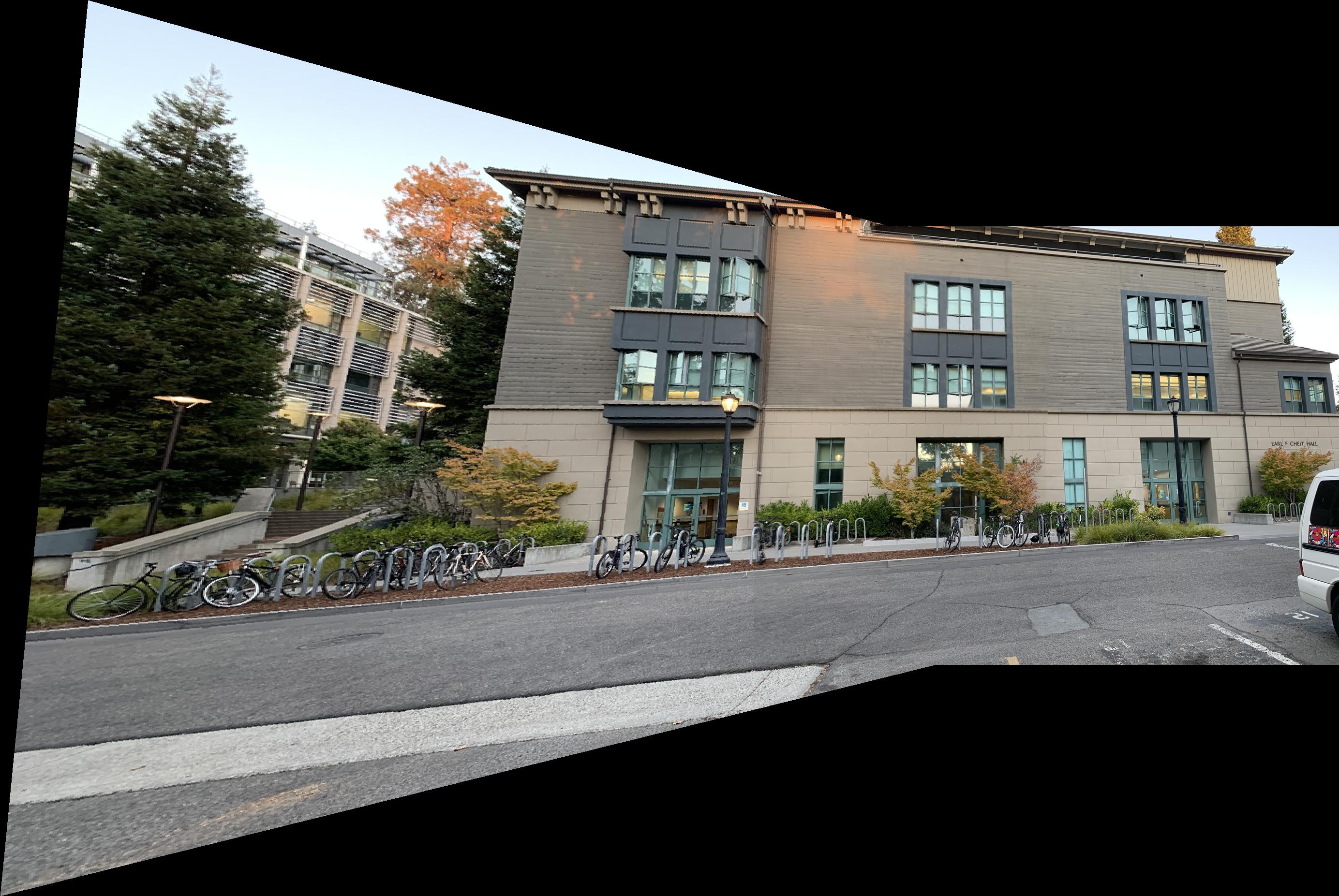
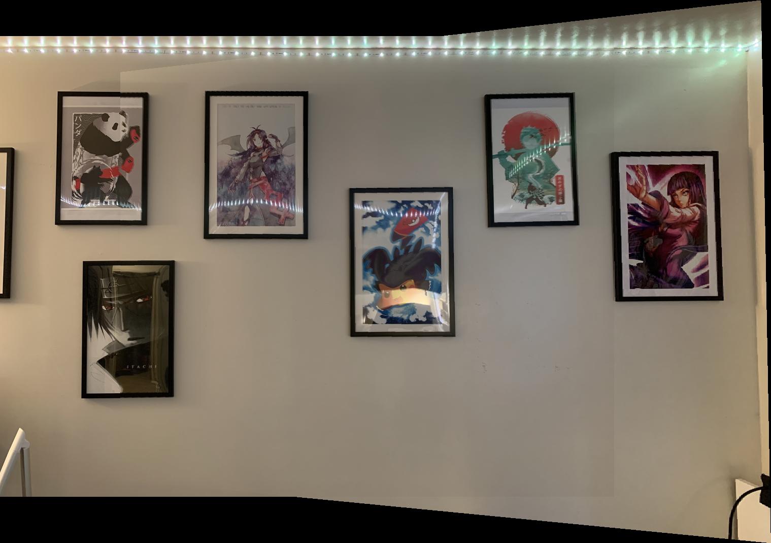
With that said, here are the mosaics.
Mosaic 1
Mosaic 2
Mosaic 3

I've learned that the ideas of computer vision such as warping images and alpha channel blending are used for many cool applications such as the panoramic mosaics that I created here. It was a great reminder that amazing things start from the simple tools that are given to us.
We will be following the paper “Multi-Image Matching using Multi-Scale Oriented Patches” by Brown et al. very closely. When I refer to the "paper", this is what I am talking about.
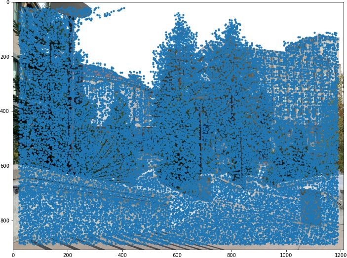
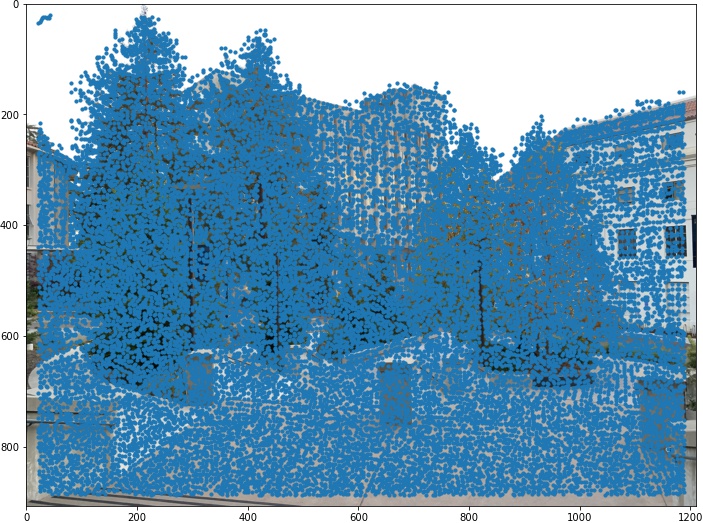
To start with the implementation of our automatic mosaic creator, I used a Harris interest point detector (that was provided to me by my instructors) to detect corners in each image. These points will be used later for correspondence (or matching). Here are some examples of images with overlaid Harris corners.
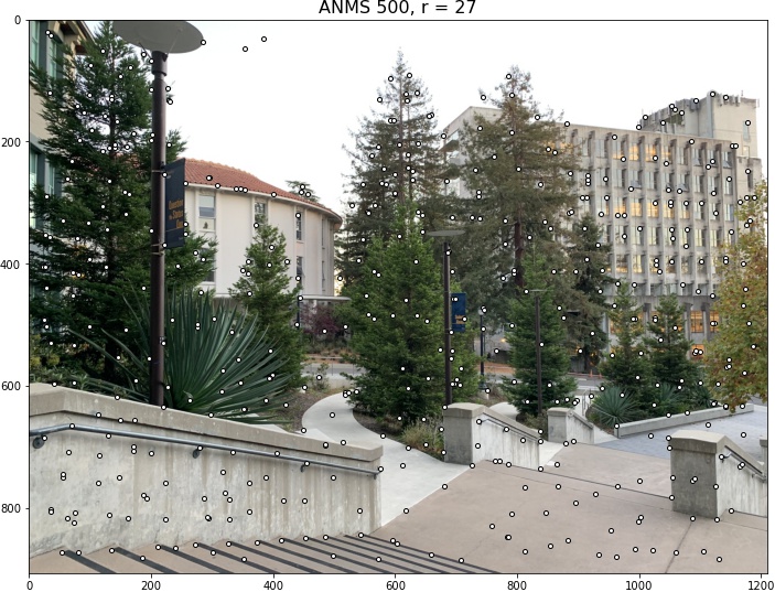
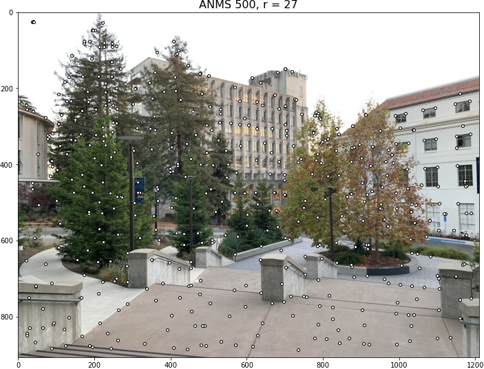
As you have seen before, there are simply way too many Harris corners! According to the paper, the "computational cost of matching is superlinear in the number of interest points", which then suggests that we should restrict the number of points we are working with. Also, it is crucial to have "spatially well distributed" interest points as the "overlap between a pair of images may be small". So, we use the Adaptive Non-Maximal Suppression strategy that the authors of the paper suggest to use. Here are the same images after using ANMS for 250 and 500 points. I included the (floored) minimum suppression radius for anyone that was curious.


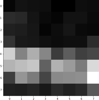
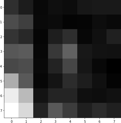
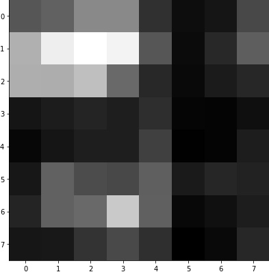
Using the feature points from earlier, we can generate feature descriptors for matching, which are 40x40 patches around the point scaled down to 8x8 patches. These 8x8 patches are then bias/gain normalized. Here are some examples.
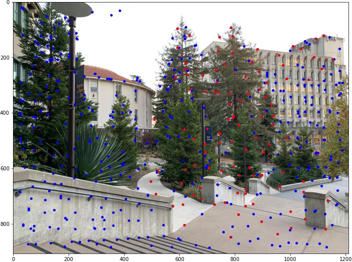
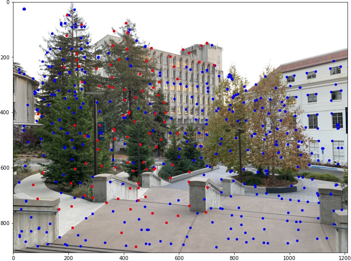
Using Lowe's trick, which is described fully in the paper, we can match the feature descriptors to find corresponding feature points. The red points below are the ones that have been matched out of all the blue ones.
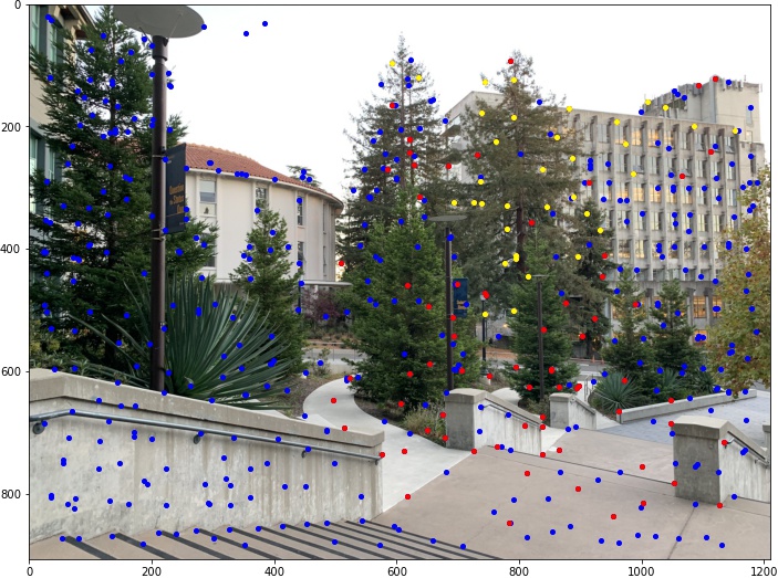
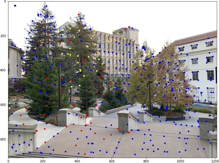
We can then use Random Sample Consensus to filter out additional outliers as the authors of the paper once again suggests to do. The yellow points below are the ones that have been chosen to be the remaining features out of all the points.
We can now use the same technique for warping and blending in Proj4A to create the mosaics (automatically this time!). Here are the comparisons.
Manual
Automatic
I've also tried 2-band "Laplacian stack" blending. However, the fact that the boundaries of the images become more apparent turn me away from using it for my mosaics, even if it may produce better blending otherwise. Here is an example from the third mosaic.
