The goal of this project is to perform image mosaicing by applying image warping techniques. We will do this through methods like homography warp images and then stitch them together to create mosaics.
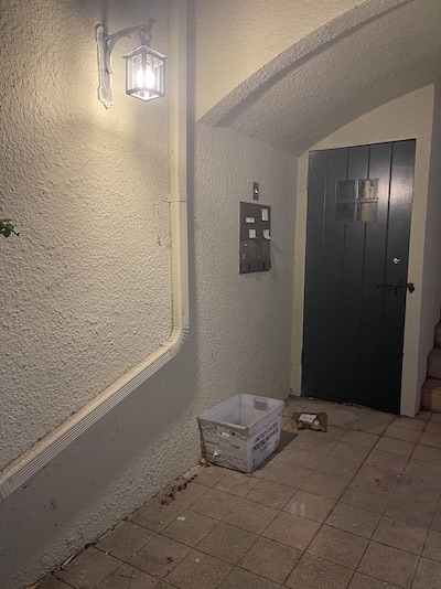
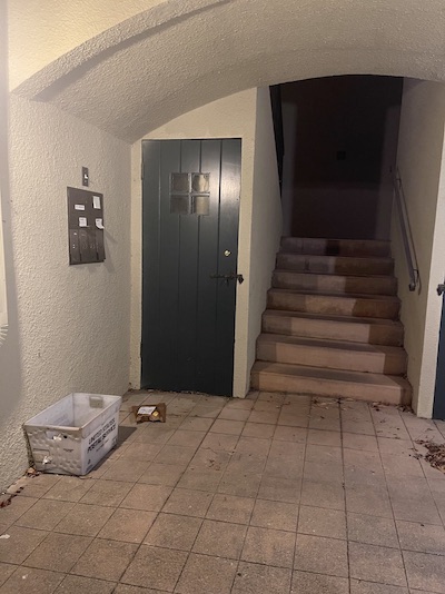
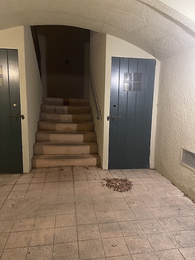
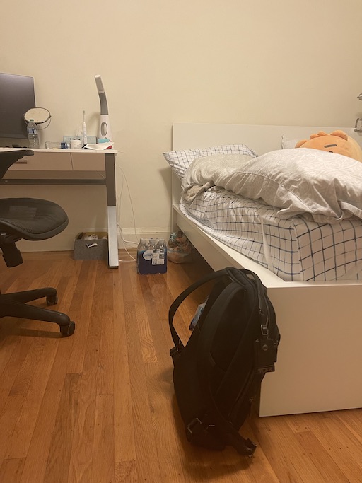
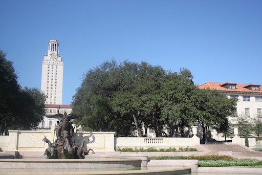
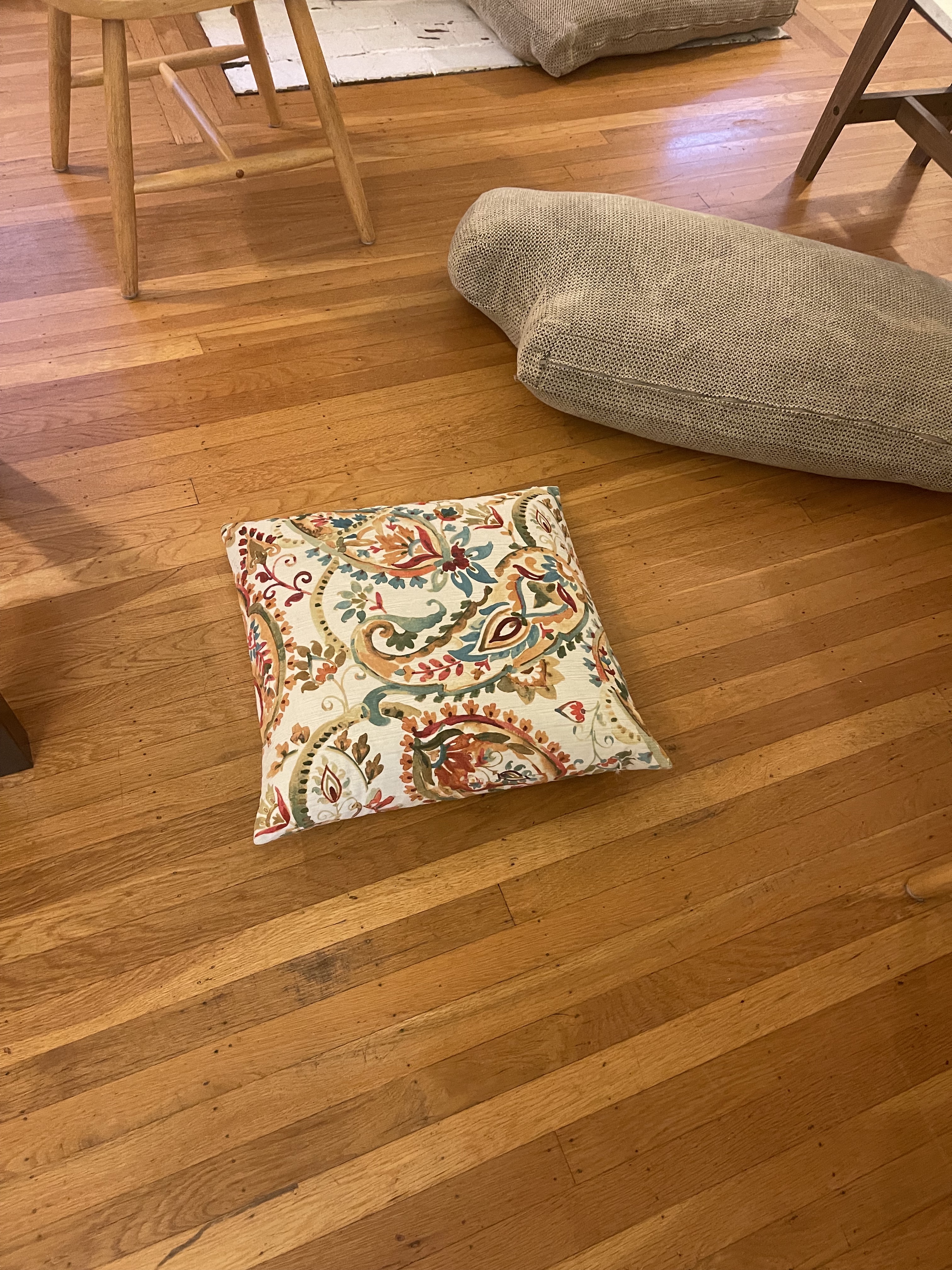
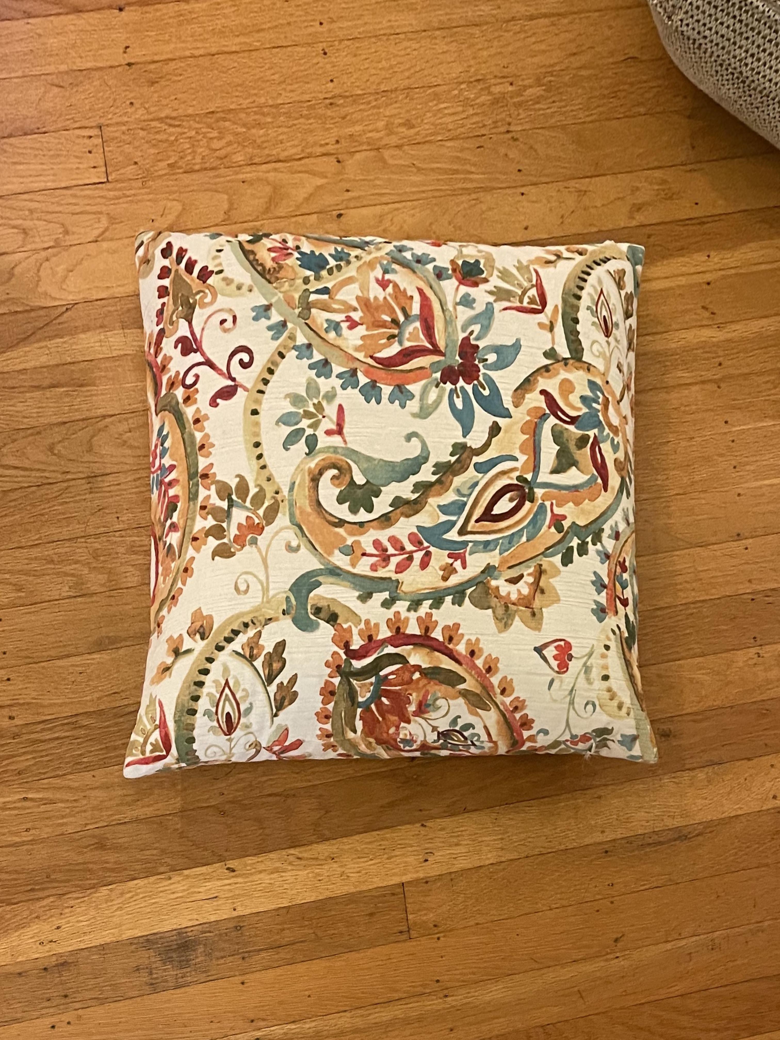
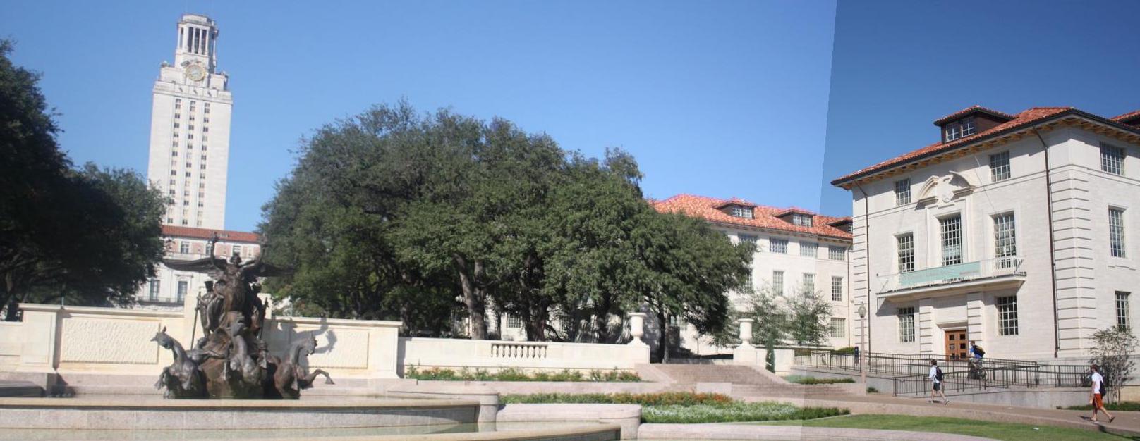
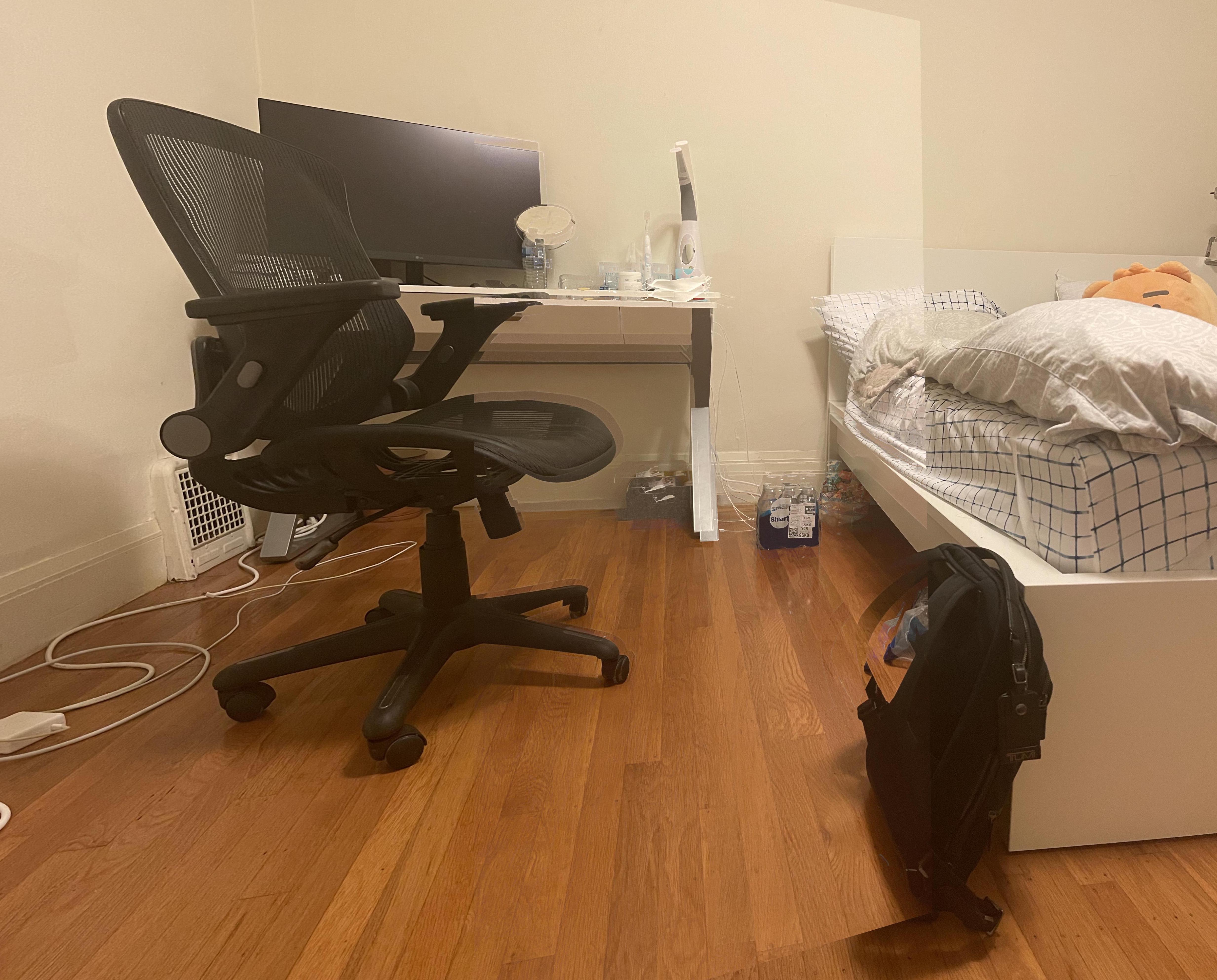
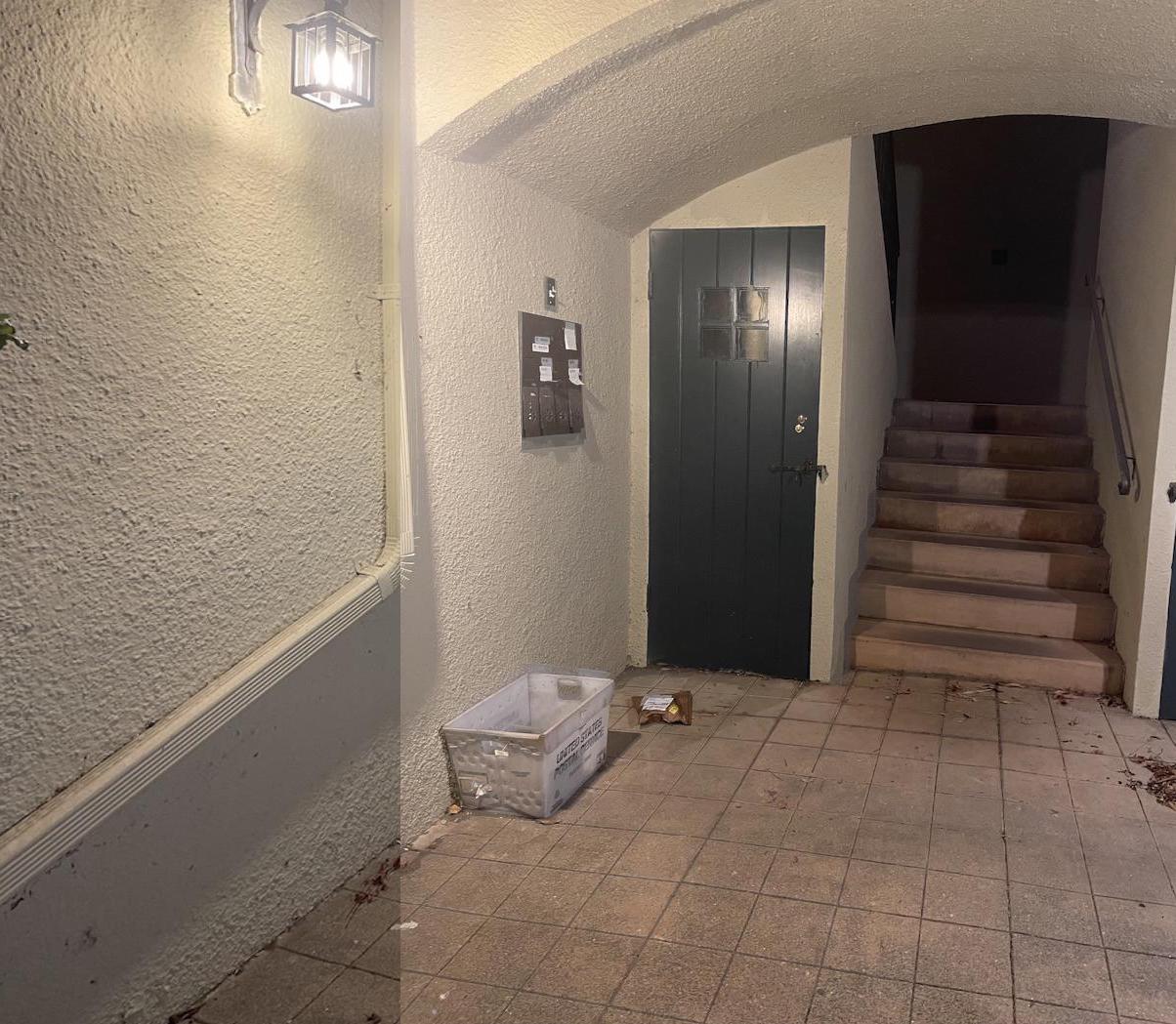
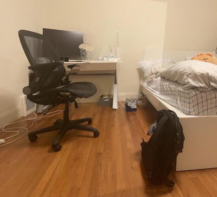
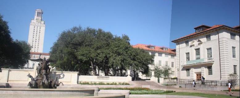
I took 3 sets of photos to use for creating mosaics. Two sets were on my phone and I also found some photos online to stitch together. I have displayed them below.

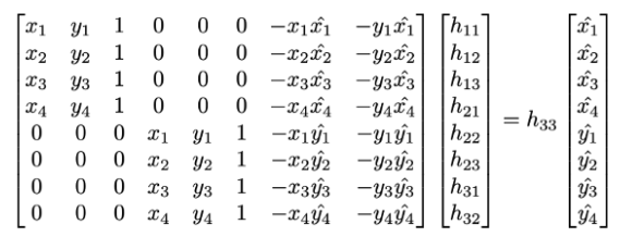
In order to retreive the homography matrix, I first selected correspondence points in both images that were shared using ginput. Then I built an A matrix and b vector as shown below to use least squares to retrieve a homography vector h by solving Ah = b. Then h was reconstructed in a matrix form to get the homography matrix.
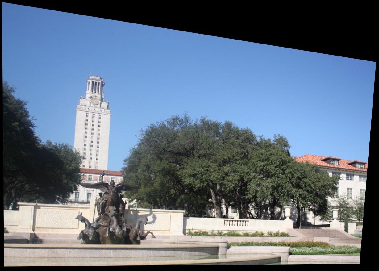
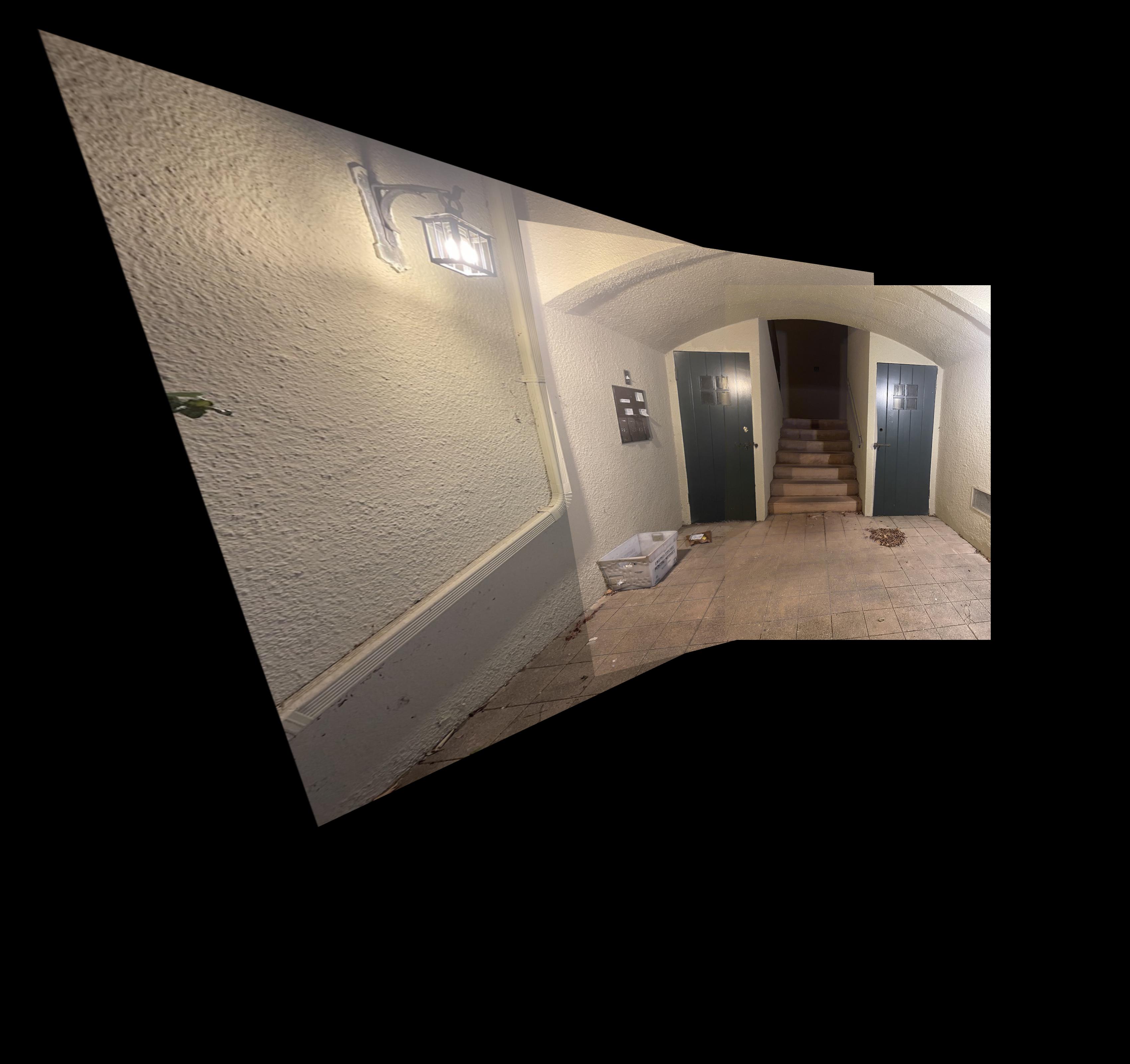
In order to warp one image into another, I first took the homography matrix calculated between the correspondence points selected for the two images. Then I figured out the potential coordinates to which the image could have been warped and shifted the image if it would end up in negative coordinates. Finally after figuring out the locations, I used cv2.remap in order to warp the image. Below I have shown the warping result for Online 1.
In order to rectify images, I first selected four correspondence points matching the corners of the square or rectangle within the image that I was trying to rectify. I then selected corresponding points to transform these points to and then computed the homography matrix to make this transformation. Using this homography matrix, I then warped the original image to the rectified version.
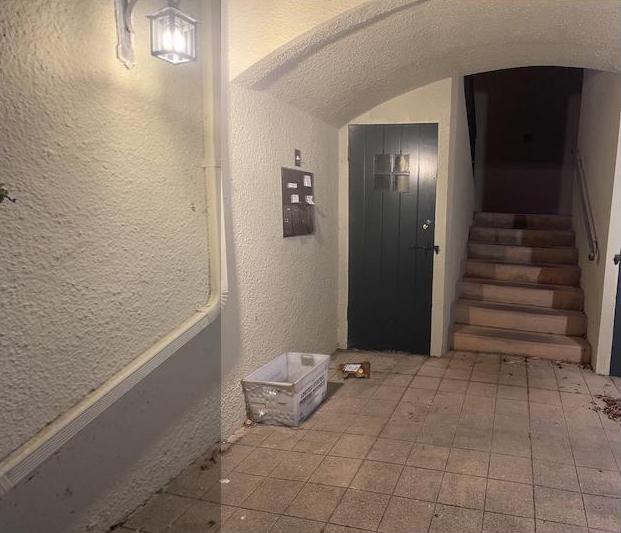
In order to blend images into a mosaic, I created a large canvas that would be big enough to fit both images. Then I took one warped image and one of the regular images, I stitched these together by figuring out the coordinates the regular image would have to be shifted to in order to be aligned with the warped image. Then I took the max in the intersection to deside which pixels would be displayed in the mosaic. For the multiple images stitched together, I took the intermediate result between the currently stitched images and selected new points for the next homography matrix and added one more image to the final result at a time.
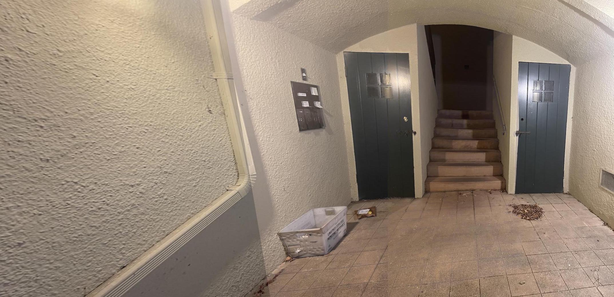
Using the provided starter code from harris.py, I found the harris corners for my images, where I have displayed a few examples below. I had to downscale many of my images in order to not have my code run for too long as too many points would be selected otherwise. An example image with the harris corners is shown below.
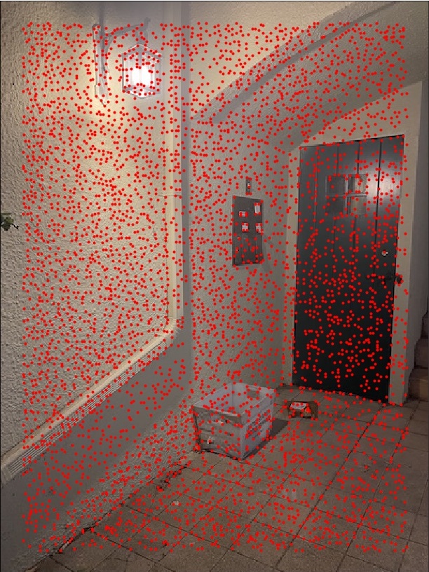
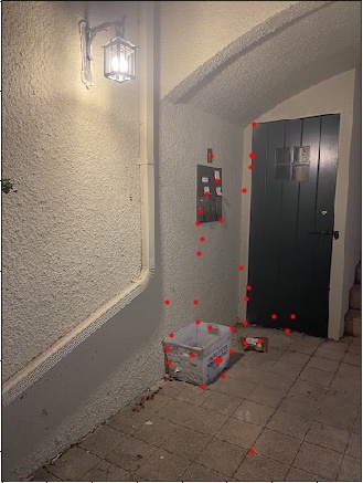
As just selecting the harris coordinates produced too many coordinates, we perform adaptvie non-maximal suppression in order to reduce the number of points in consideration. To perform this algorithm, we calculate the distances from every point to every other point and then compute the minimum squared distances for the points while making sure that the corner strength associated with one point is less than 0.9 * the corner strength of another point. Then we sort the points based on the minimum distances values in descending order and then take the top 500 points. An example of the image points preserved after Adaptive Non-Maximal Suppression is shown below.
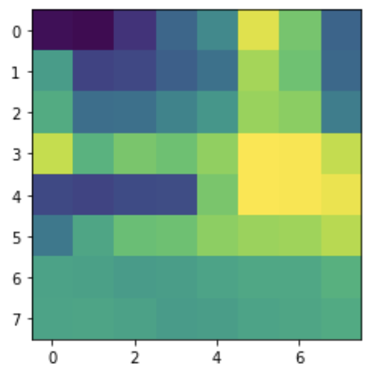
In order to extract feature distriptors, I took a 40x40 axis-aligned block around every single point returned after Adaptive Non-Maximal Suppression was performed and rescaled them to 8x8 blocks. Then I flattened these blocks into length 64 vectors in order to represent each feature. An example feature is displayed below.
In order to match features, we calculate e1_NN and e2_NN which represent the smallest and 2nd smallest squared distance error between a feature from image 1 to features on image 2. We use thresholding on the value e1_NN / e2_NN in order to determine which features are able to be used for matching with the threshold value set to around 0.3. We can see that some points are still incorrect, but these are cleaned up during RANSAC. Below are some of the images with the points that are saved after feature matching is used.
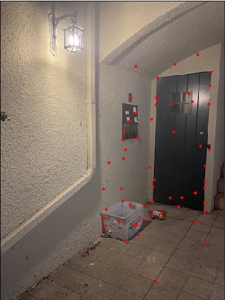
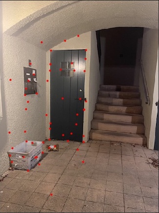
After performing feature matching, I used RANSAC to compute the best points to use for my homography matrix calculation. We do this by first selecting 4 random points from the correspondence points returned from feature matching and computing a homography between the random points selected from each image. We then use this matrix in order to transform the points from image 1 and image 2 and then compute the squared error between the transformed image 1 points and the image 2 points. If the error was less than a specific threshold value, we considered the points to be inliers. Then we take the largest set of inliers to be used for the points in our homography calculation for automatic stitching. We can see all the correspondence points are valid now for the examples below.

Finally, I used the stitching code from project 4A with the automatically selected points in order to generate these mosaics below. I have also shown the manually stitched images again, we see improvement with alignment (especially in the entrances example), but part of this is likely due to the fact that I took multiple attempts to constantly reselect multiple points in part A to get better results that looked cleaner, and this work was now omitted due to the automatic point detection. Some results may look less clear due to the resolution difference as I had to scale the images down to get them to align with the algorithm.
I found it really cool how I could use pictures that I took through my own phone cameras to generate these image mosaics and thought it was interesting to apply simpler techniques like least squares from prior classes to be able to create these visual products. However, I also learned how important it was for the photos I took to be good, which was limited by the lack of a tripod, otherwise my results wouldn't be as good.
In terms of the second part of the project, I also found it very cool to be able to automatically determine correspondence points for the images to remove the human bottleneck of having to manually select the points. Also knowing that the algorithm would be able to more accurately select points that are in similar locations rather than my manual eyeballing which may have been off by a few pixels was also reassuring.