Part.1 Coordinates
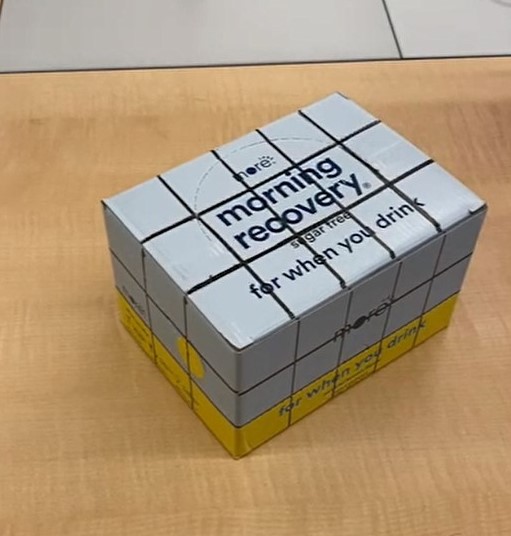
Our goal of this project is to project a 3d structure, cube, on the grid drawn on the box. And in order to do this, we need to set 3d world coordinates and the corresponding 2d image coordinates for each frame of the video. Hence, the image above has the grids drawn and the corresponding 2d points.
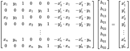
The camera transformation matrix is solved with the least squares setting below:
After solving the camera transformation matrix, we can get the corresponding 2d image points for the 3d world coordinate for each frames.
Part.2 2D image coordinates for each frames
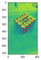
For the first frame, we got the 2d image coordinates by manually plotting them, but how do we get the 2d points for rest of the frames? As doing so manually will take a long time, this was possible to achieve with harris corner detection algorithm. After getting harris corners from the second frame, I was able to compute the nearest corners of these points from the corners attained manually at the first frame. And this is done until we get 2d points for rest of the frames.
Part.3 Drawing 3d structure, Cube
 succss 1 succss 1
|
As we can compute the camera transformation matrix for each points in every frame, we can now draw a 3d structure on the image space. We can convert each corners of the cube to 2d coordinates and draw a line between the corners to create a cube like the image above. And doing this for every frame, we can make it a gif like below:
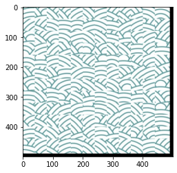
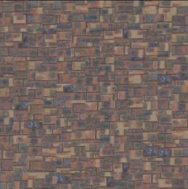
Image Quilting: Overview
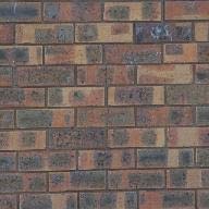
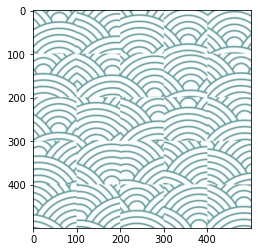
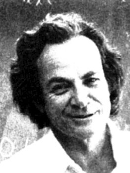
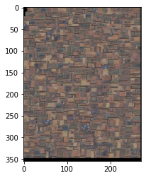
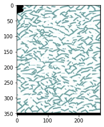
In this project, we use an image of pattern to create a larger size of the pattern and extract the properties of the pattern to create another image to have the pattern, which is known as texture transfer. And the two images above are the patterns I will be using throughout the project.
Part.1 Random Patching
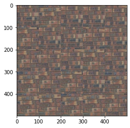
First, we take a look on how the newly created patterns would look like after if we randomly select a portion of the original pattern image and patch them together until we fill out the larger size of the new image. And the following are the results.
The results behave not so bad, but the seams are noticable and we want to remove these to create a more seamless pattern.
Part. 2 Simple Patching
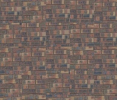
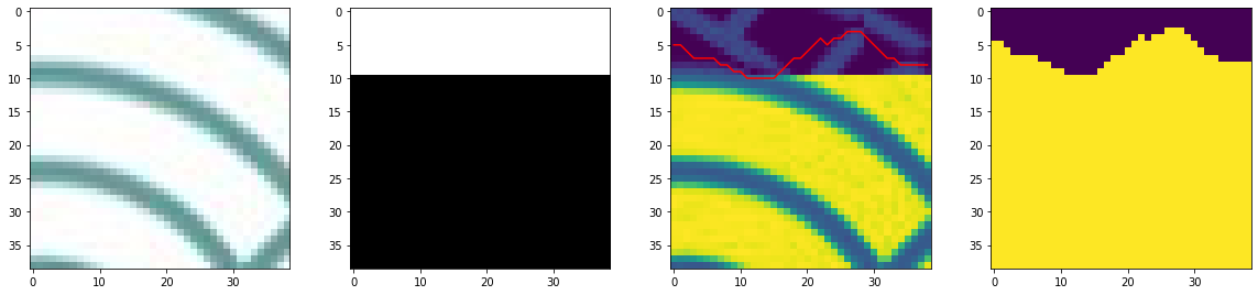
In part 2, we use a bit more advanced method to create the new pattern a bit more seamless. We create a mask and a template. Then, we mask a portion of the original image to find which image has the least SSD error comparing with the template we created while making new pattern image. After that, whichever has the least error will be allowed to be patched on the newly created image. This method allows us to create a bit more seamless pattern image, but there are some issues as the mask is a bit blunt. The following are the newly created images with the simple method.
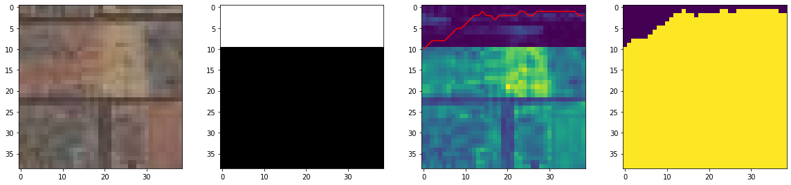
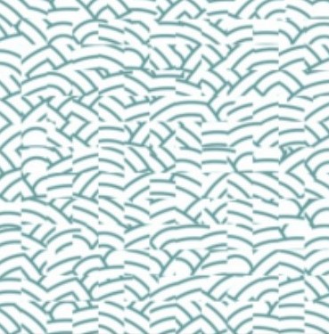
Part. 3 Cut Patching
In this part, we want to create a less blunt mask so the newly created pattern can be even more seamless than the simple method. In order to do this, we use cut function and a new cost function referred as bndcost, which combines the SSD values of the RGB channels. And the followings are the image I obtained with the new method.
After iterations of 100 epochs with a learning rate of 1e-3 and data augmentation, following are some of the results I gained. Blue points are the prediction from the CNN and the green points are the ground truth label from the dataset:
Part. 4 Texture Transfer
In the last part of our project, we want to combine the textures we had to an image of Fynman. After this, we can express one of the most famous Physicist with bricks and japanese patterns. And the followings are what I obtained.
 succss 1 succss 1
|
 success 2 success 2
|