Team member: Thee Ho, Project: Light Field Camera & Image Quilting
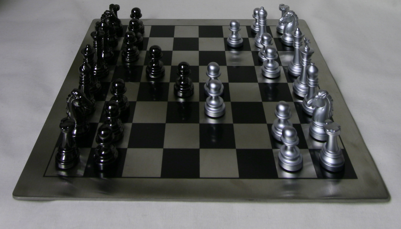
In this project, we mimic the effect of depth refocusing and aperture adjustment digitally by averaging pictures taken with a 17x17 array of cameras. With use pictures taken from the Stanford Light Field data-set.
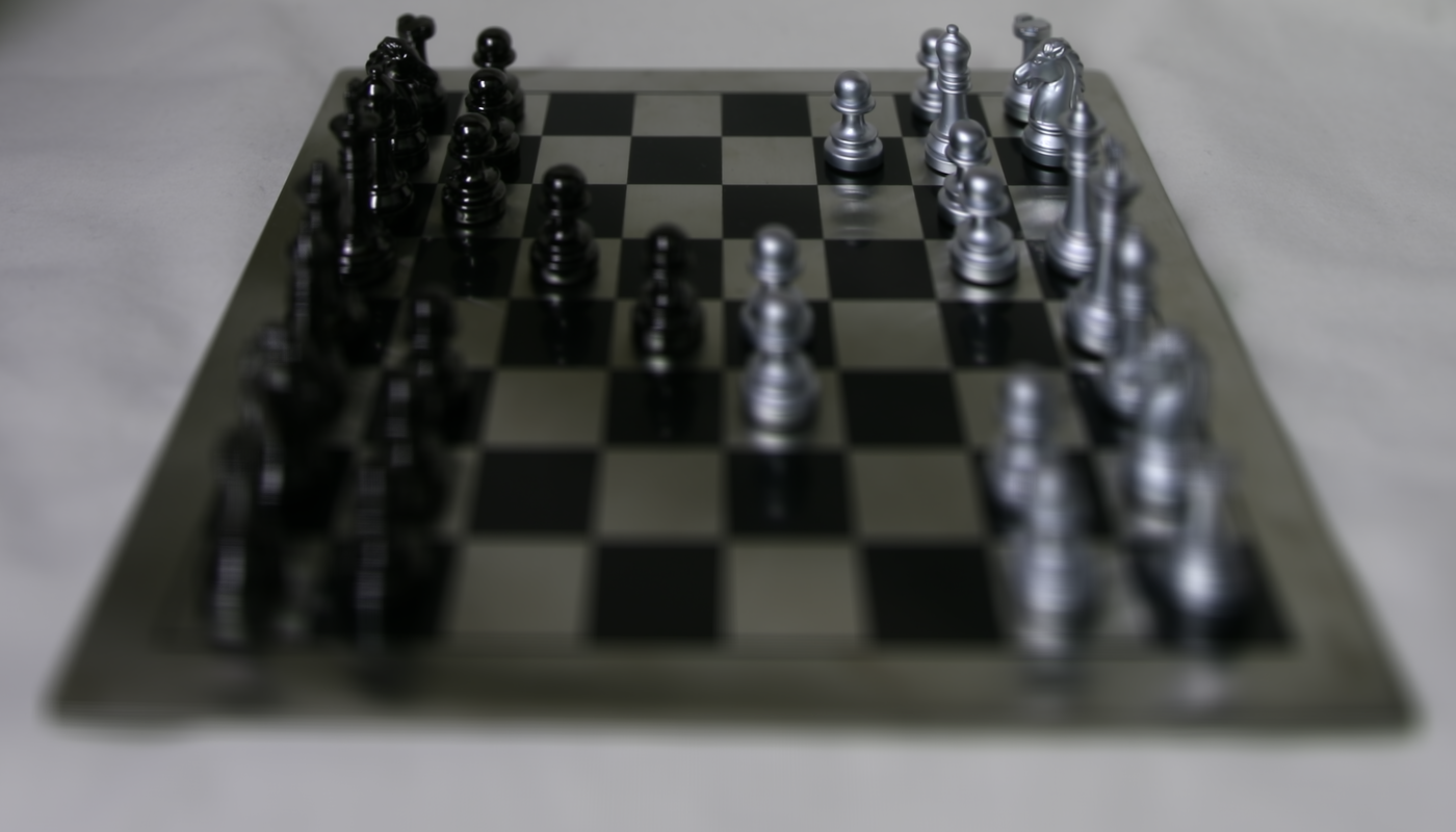
When we average images in a lightfield, object far away will appear more in-focus while object near the camera blurry. This is because when the camera shifts it's x and y position, the position of far-away objects changes less than that of nearby object. Thus, to focus on object at arbitrary depths, we must first digitally shift each images in the light field by the appropriate amount before averaging.
First, we find the mean x,y position of the images in the grid. Then for each image, we shift the x and y position by c*(x-x_mean, y-y_mean). Finally, we average all the resulting images.
Bellow is a sample depth refocusing with different values of c.
Finally, we create a .gif which run depth refocusing on values of c in [-0.1,0.55]:
Bellow is the result on the Lego light field:
Averaging more pictures in a lightfield simulate a camera with larger aperture. We use this to create the effect of a picture taken at different aperture by averaging varying amount of pictures around a radius.
At N=0, we only take the middle picture at (8,8), with N=2, we average the middle 9 pictures around picture (8,8) to create a photo taken with larger aperture, with N=3 we average the middle 25 photos to increase the aperture further and so on.
Bellow is some sample results with different values of N.

Finally, we create a .gif that runs this process for N in [0,8]. We start out only taking the middle photo and ends with averaging all 289 photos in the lightfield.
Bellow is the result on the Lego light field:
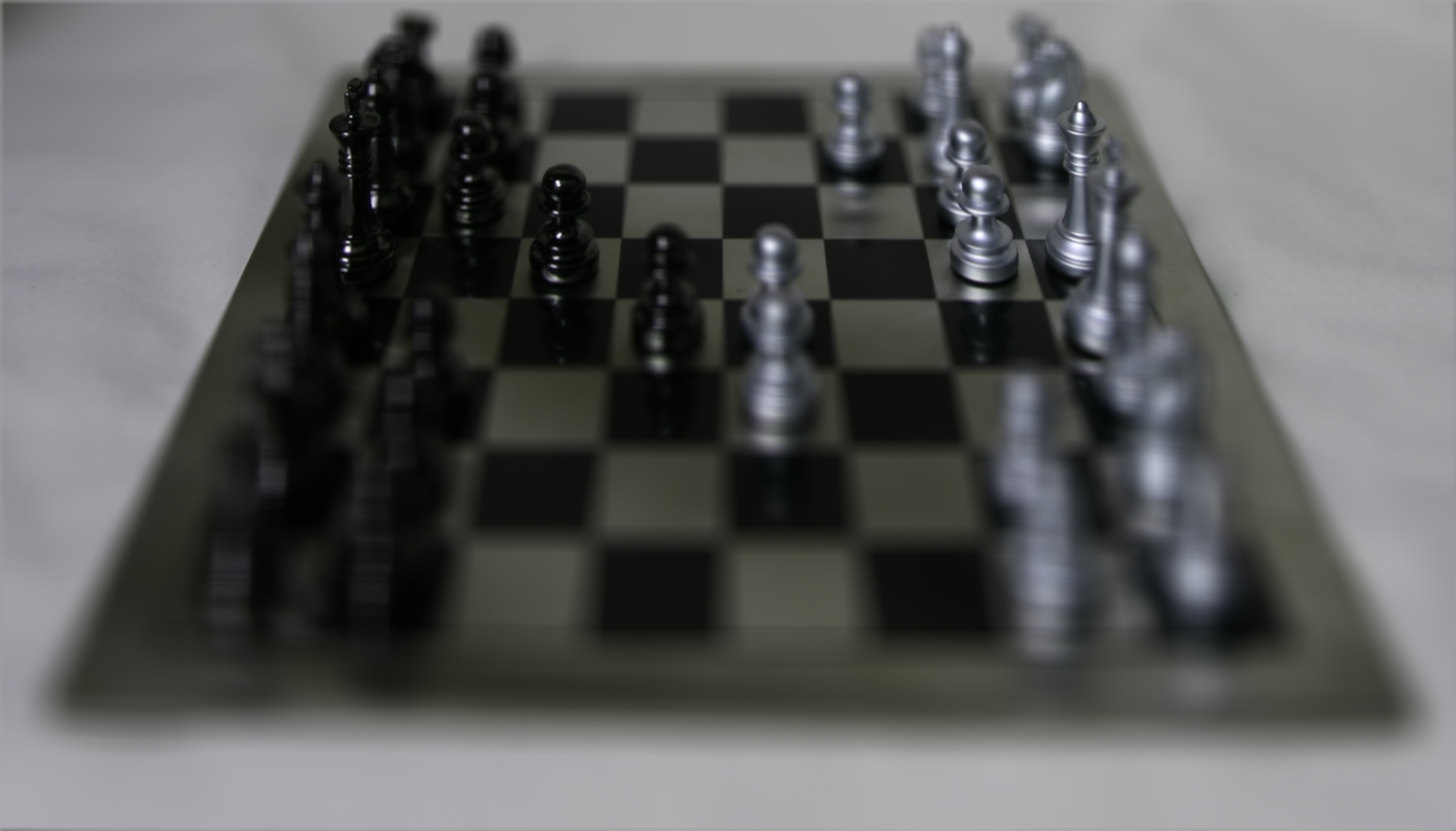
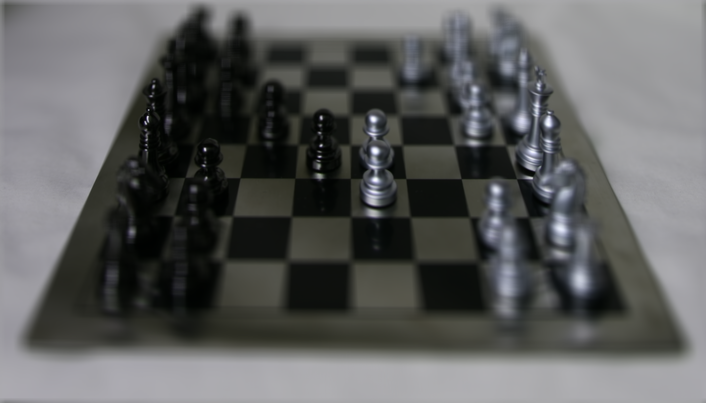
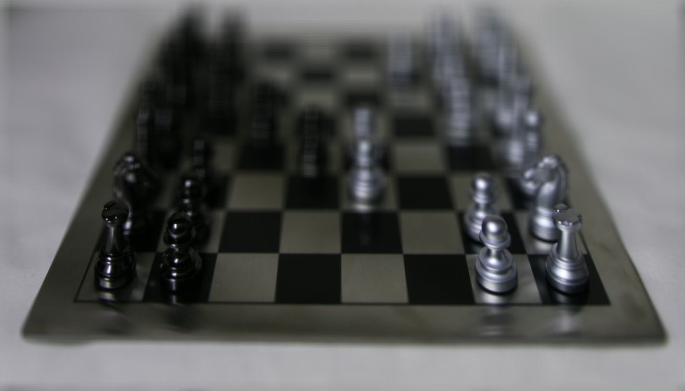
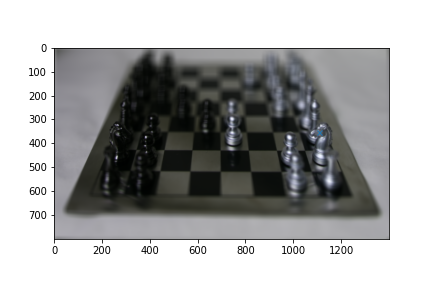
We first capture user input using plt.ginput(), then we much search for the best shift value to create the effect of the camera focusing in on the chosen point. The approach used is similar to Project 1. We do this by taking a 100x100 pixel region around the user input, then search for all x,y shift in the range [-15,15] that would give the smallest L2 error between the middle (8,8) image and the top left (0,0) image.
After obtaining the shift value we divide by the difference in x,y position between the (8,8) and (0,0) image to obtain the c value. Finally, we apply the same method as part 1 to refocus the image around the chosen point.
Below is some sample the result (Points chosen by the user are marked with a blue 'X'):


In this project, we explore image quilting for texture synthesis and texture transfer. First we naively sample random patch. Then sample overlapping patch 'similar' to it's neighbor. Finally, seam finding is used to best merge two overlapping patches. We apply our result to texture transfer by modifying our cost function to include the difference between target patch and sample patch.
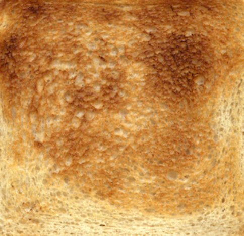
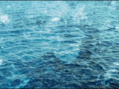
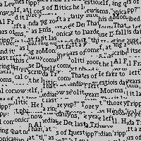
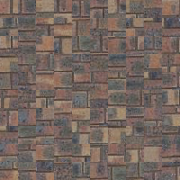
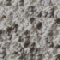
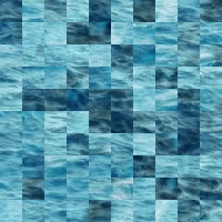
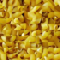
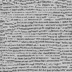
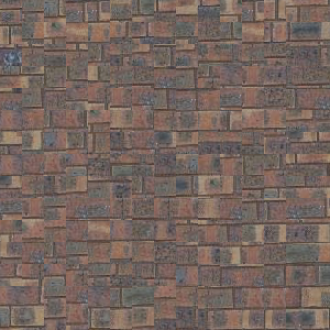
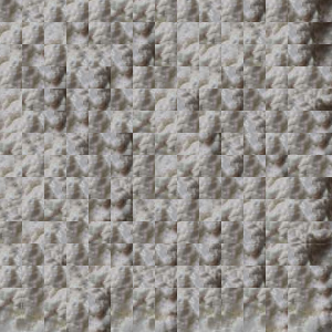
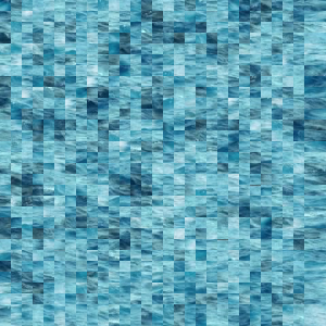
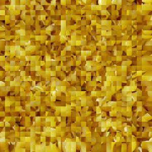
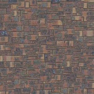
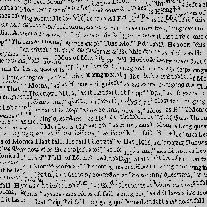
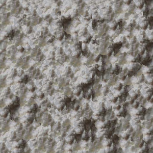
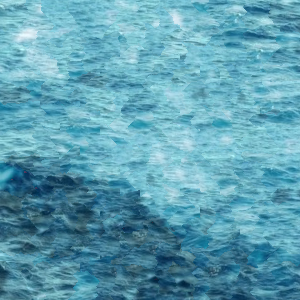
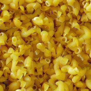
Bellow are five textures use in this project:
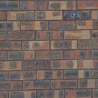


The first approach is to naively sample random patch from the texture sample image. You can see the patch square distinctly. Bellow are five examples:
To achieve continuity between patches, we change our sampling to reject patches that mismatch with existing patch above a tolerant threshold. Instead of specifying patch size, now we include an overlap parameter specifying how much two neighboring patches overlap. Then for each sampled new patch, we calculate the L2 error between the new patch and existing patch's overlap region. We accept the sample if this error is less than the tolerant threshold.
As you can see result is better than Part 1 but some discontinuities are apparent. Bellow are five examples.
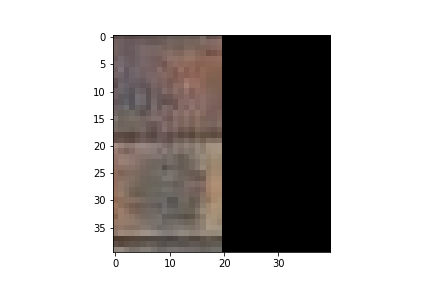
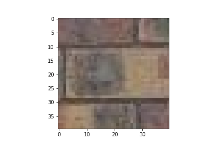
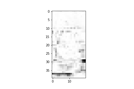
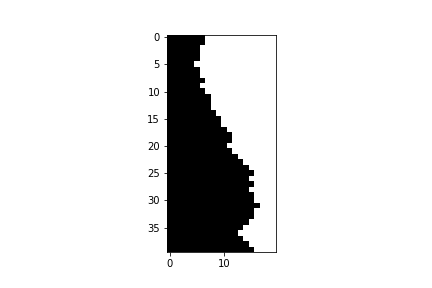
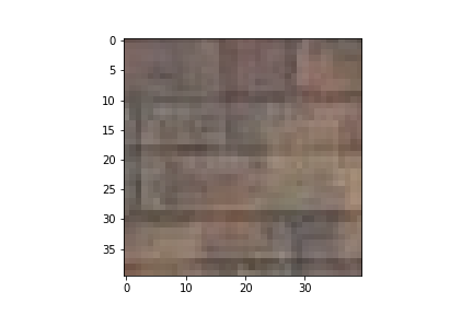
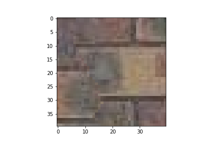
Instead of using a binary mask for overlap region, we can improve our method by masking along the min-cut path. The seam finding approach compute the L2 error for each pixel in the overlap region, then it finds the min-cost path the resulting 2D grid of L2 errors. The result is then used to create a horizontal and vertical mask to merge the sample with its neighbors. We illustrate the proccess for the top left patch and it's neighbor to the right. Each patch is 40x40 and the overlap region is 20x40. We show the two neighbors, the L2 cost grid, the min-cost path and the final result of merging:
We compare the three method for the brick texture. As you can see the result is much better than simple overlapping.
Finally, here are some results of seam finding.
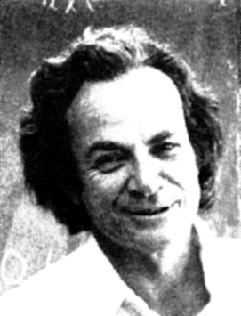
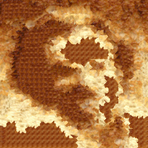
To perform texture transfer, we modify the seam finding method to account for the target image. When sampling for texture patch, in addition to L2 error with overlapping neighbors, we add a second term to the cost representing the L2 error between the texture patch and target patch. This encourage the sampled patch to match the target patch in appearance. The rest of the quilt_cut() function is left unchanged.
Bellow is some two result of texture transfer. A challenge is finding the right patch size and alpha value. Larger patch size cause only the general shape of the target to transfer over while smaller patch size takes much longer to generate the resulting image.