CS194-26: Image Manipulation and Computational Photography
Sping 2020
Project 1: Images of the Russian Empire
Zixian Zang, CS194-26-act
Overview
The goal of this assignment is to take the digitized Prokudin-Gorskii glass plate images and,
using image processing techniques, automatically produce a color image with as few visual artifacts
as possible. In order to do this, I extract the three color channel images, place them on top of each
other, and align them so that they form a single RGB color image.
I use L2 Norm ,
Edge Detection and Image Pyramid for image alignment, implemente
the options of Auto Cropping the image according to the shifting in channels alignment,
and improve the image quality with Histogram Equalization algorithm.
Section I: Image Channel Alignment with Image Pyramid
Raw Pixel Matching VS Edge Detection (Bells and Whistles)
The algorithm I use to determine the similarity between two image matrices is Sum of Squared Differences (SSD),
also known as L2 norm. The formula is simply sum(sum((image1-image2).^2)) where the sum is taken over matrices entries.
The naive way of comparing the channels is basically using raw pixel values as inputs to the SSD function after shifting.
But this method does not perform very well since there can be significant differences in an area of the image between the
raw matrices of channels. For example, if there’s a large area of green on the RGB picture, then there would be a bunch of
relatively high pixel value at the same area on green channel and relatively low value at that area on the other two channels.
To solve this issue, I use the filter [-1, 0, 1] along the rows and columns to extract the edge information vertically and
horizontally. Then with the help of SSD, I use the resulting pixel value matrices as reference to find the displacement value of
the green and red channels.
Detail Steps
1. Before aligning the channels, 8% of area along each edge is cropped to eliminate the noise.
2. The filter [-1, 0, 1] is applied to the pixel matrices. The advantage of using this filter over other convolution
kernels is that the result of this filter can be expressed as M[2:,:] - M[:-2,:] and M[:,2:] - M[:, :-2] to extract horizontal and
vertial features from the images. Considering the images are represented as numpy arrays, this operations performs excellent on the aspect
of runtime and avoid explict for loops.
3. Use image pyramid to search for the correct displacement between color channels, which significantly narrows the space
of possible displacement values that are attempted. The matrix sizes between adjacent layers have ratio of 2 along the axes. Inside each
layer, I search in [-5,5] range on each axis. At each displacement position, the error value is calculated as the sum of SSD values for both
vertical and horizontal edge feature matrices. After calculating SSD values, the position with the least error value is chosen to be the correct
displacement.
4. Use the displacement value found in the previous step, green and red channels are shifted relative to blue channel. Image
channels are stacked back together after shifting to create the new image file.
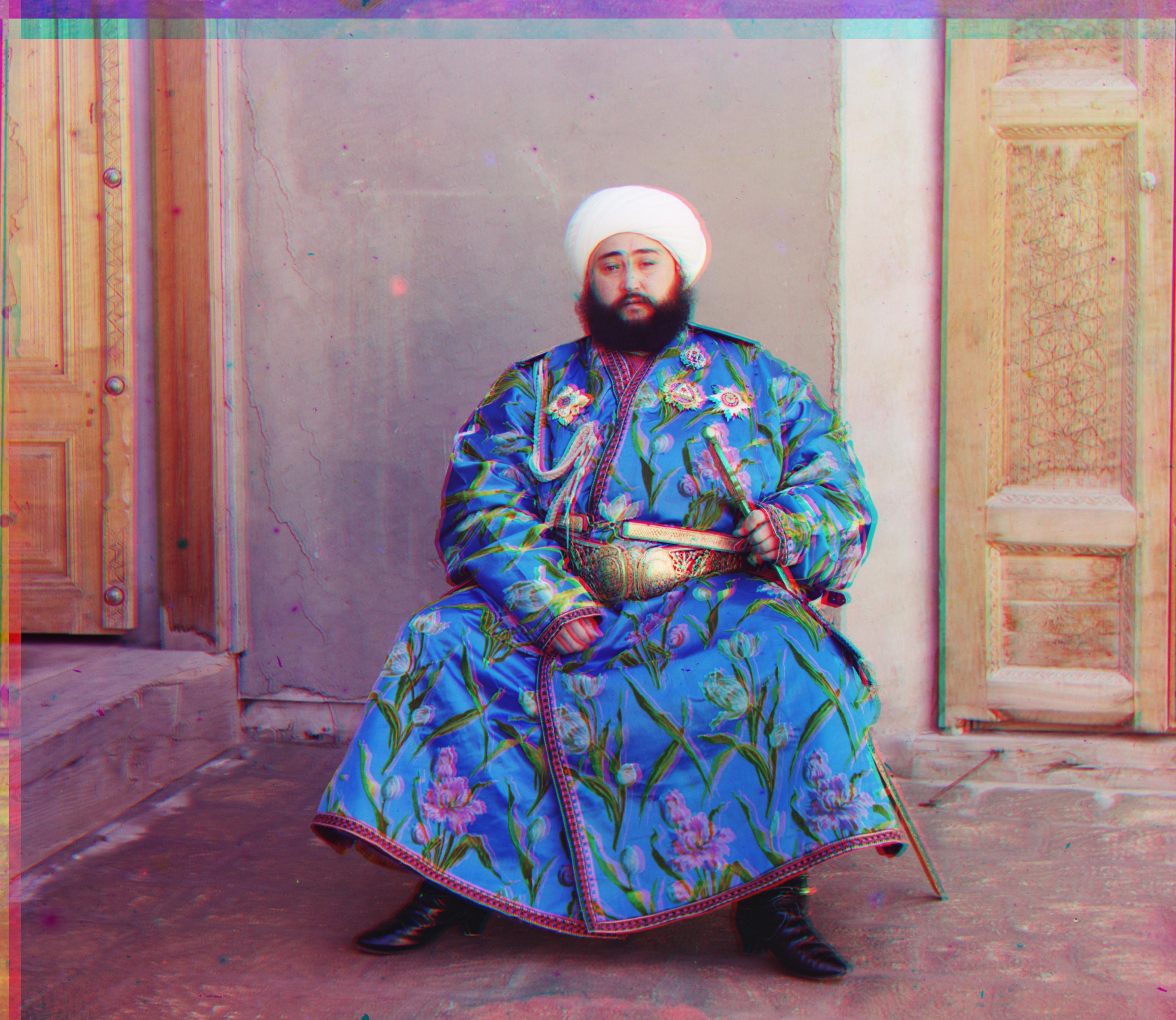
Here is a demonstration of the improvement in alignment when edge detection is used.
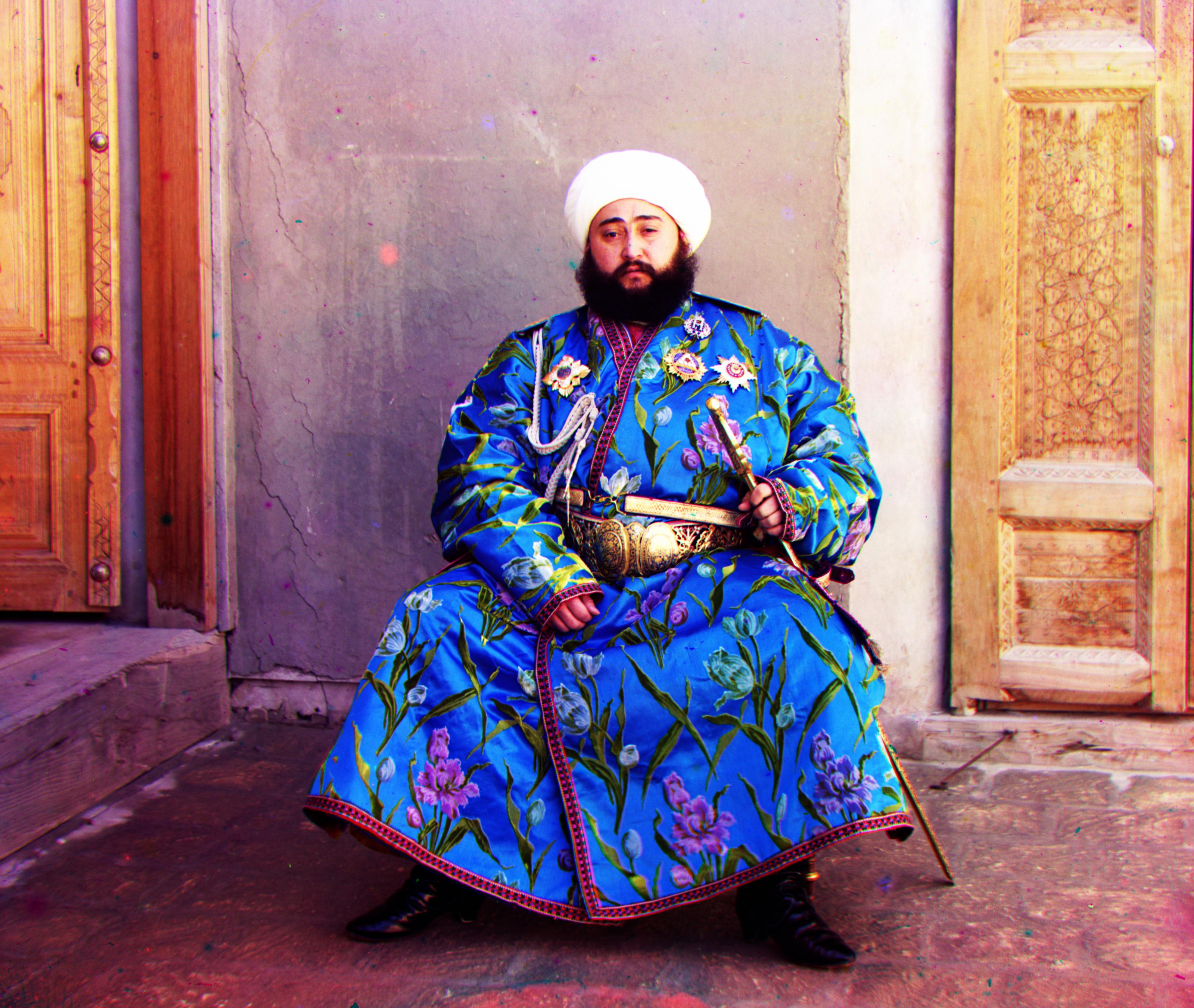
Results From emir.tif
Raw pixel alignment
|
Raw pixel (detail)
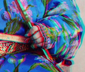
|
Edge detection (detail)
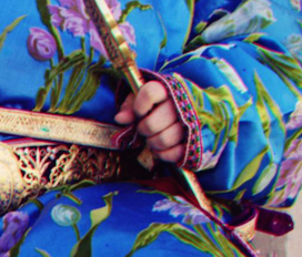
|
Edge detection alignment
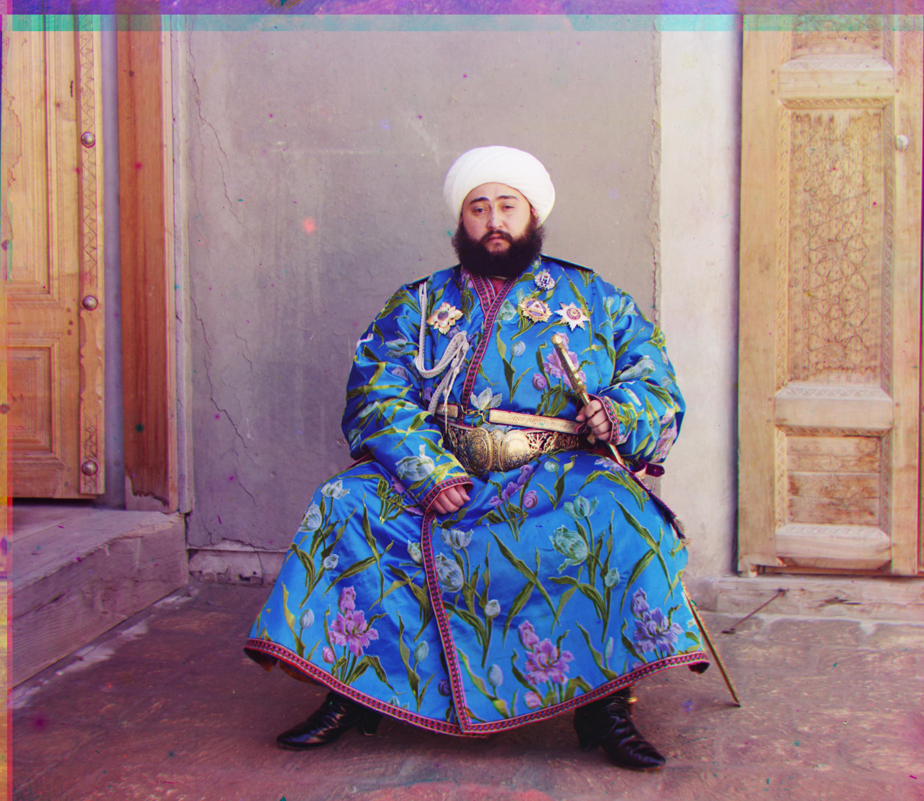
|
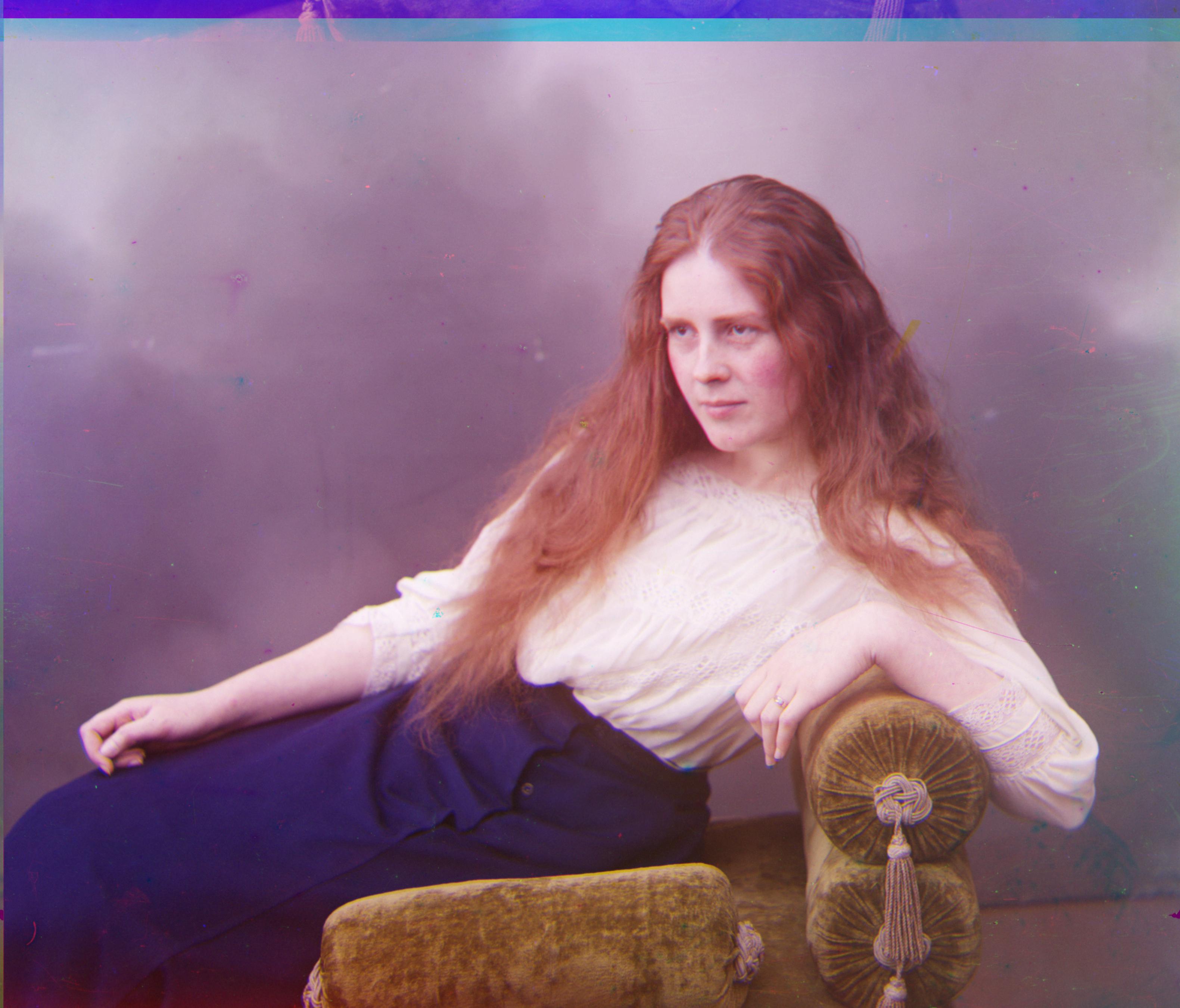
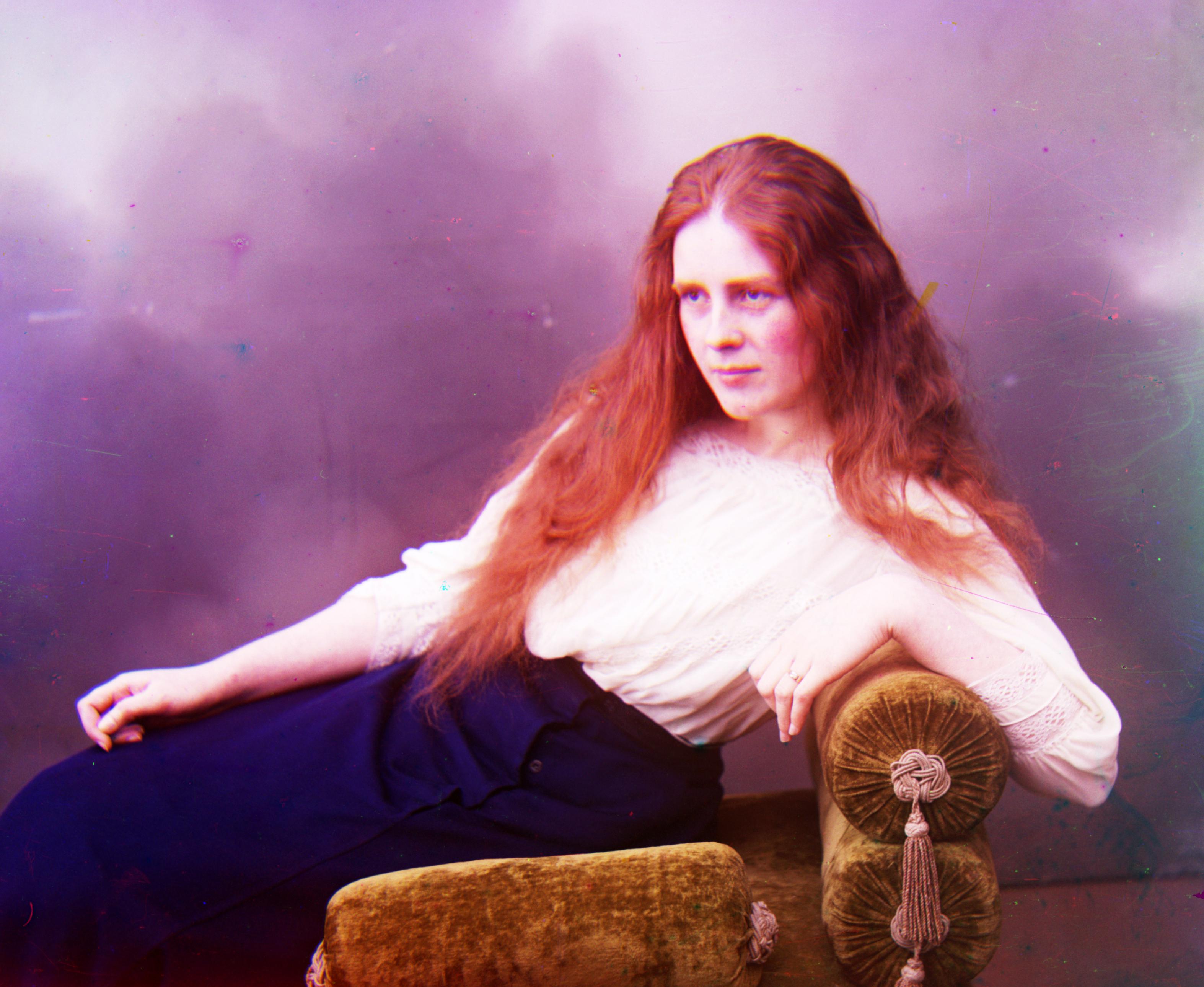
Results From lady.tif
Raw pixel alignment
|
Raw pixel (detail)
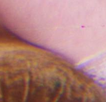
|
Edge detection (detail)
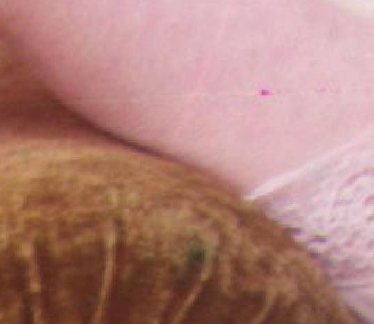
|
Edge detection alignment
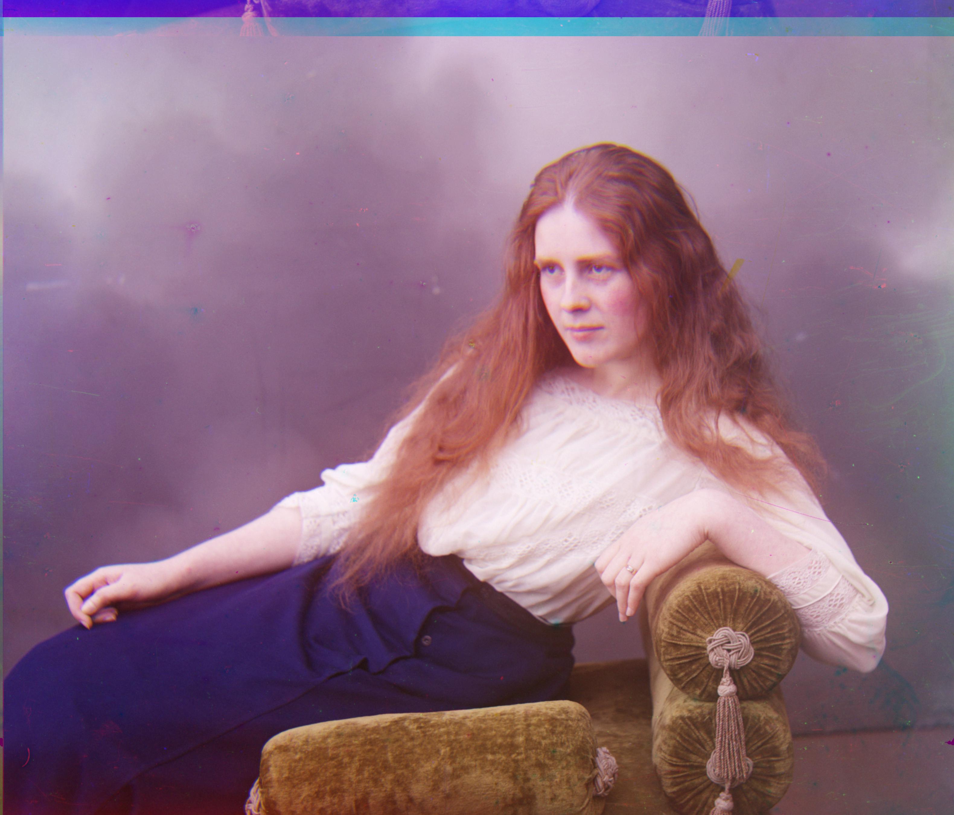
|
Section II: Improve Contrast In Images
Histogram Equalization(Bells and Whistles)
After aligning the image channels, I use Histogram Equalization algorithm to improve the contrast within images.
This technique effectively spreads out the most frequent intensity values, i.e. stretching out the
intensity range of the image.
Detail Steps
1. A histogram of pixel values is made.
2. Cumulative sum along x-axis of the histogram is computed.
3. Re-normalize cumulative sum values to be between 0-255.
4. Get the values from cumulative sum for every index in flat, and set that as the new image.
Here is a demonstration of the improvement of image quality in contrast.
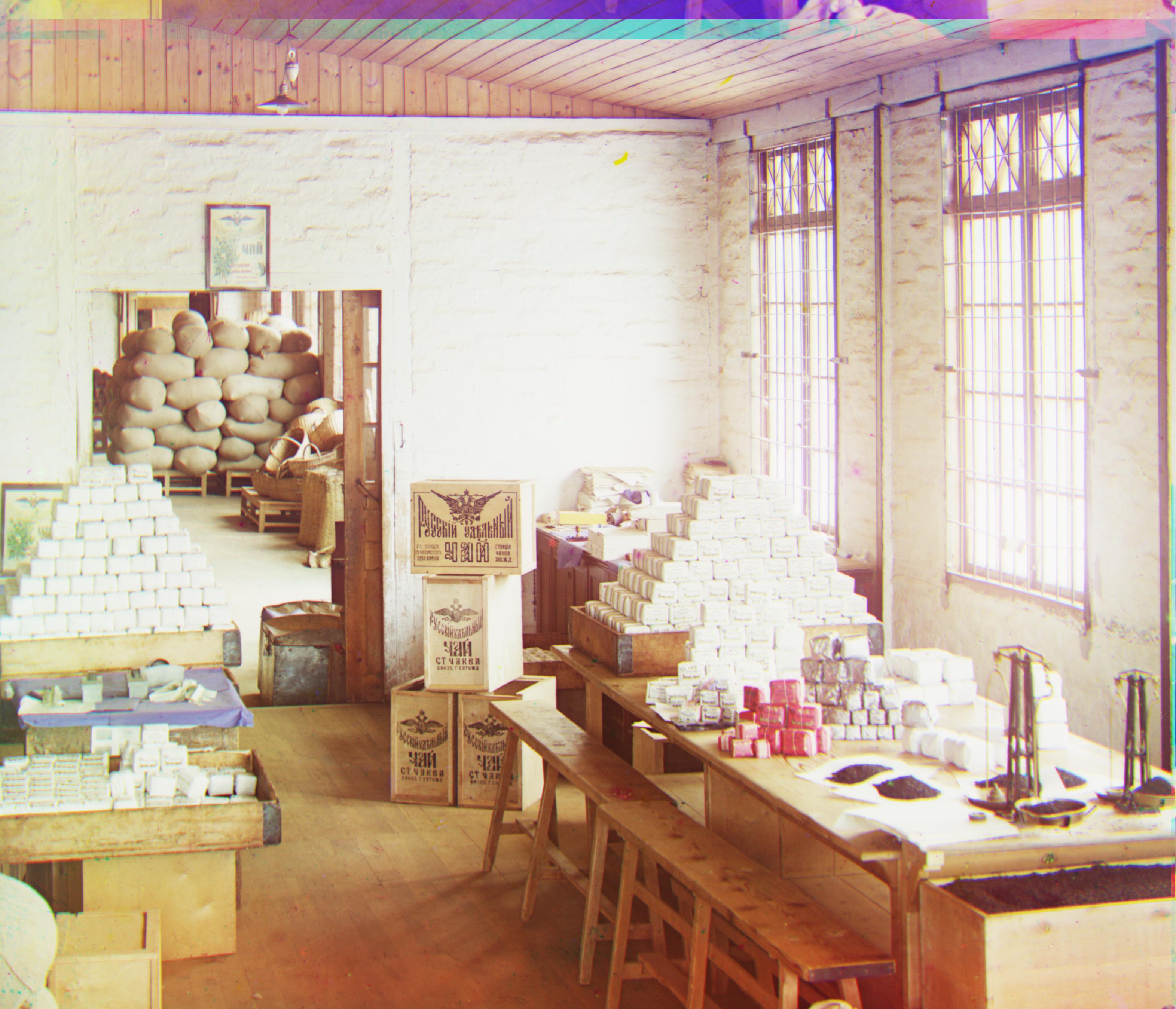
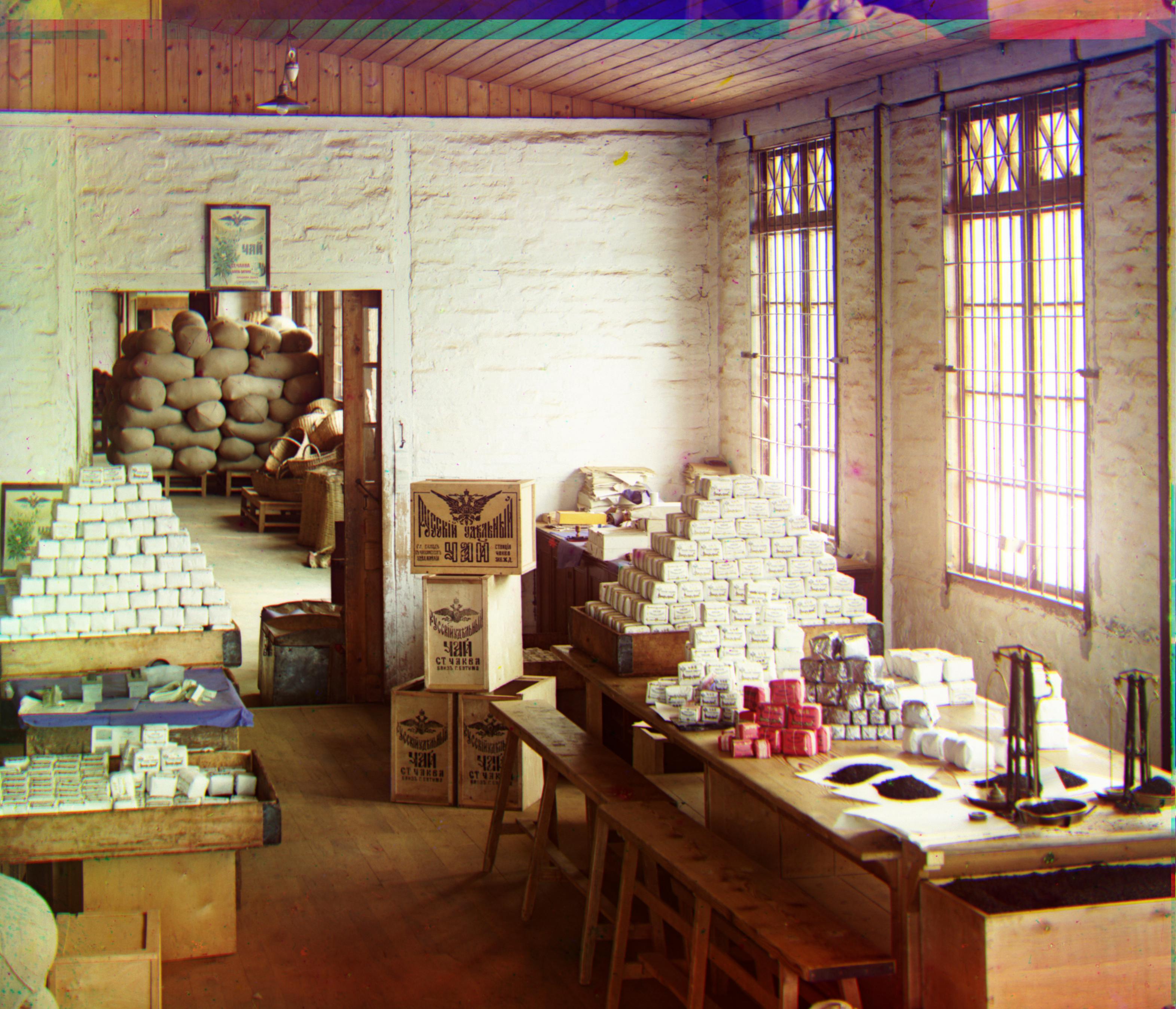
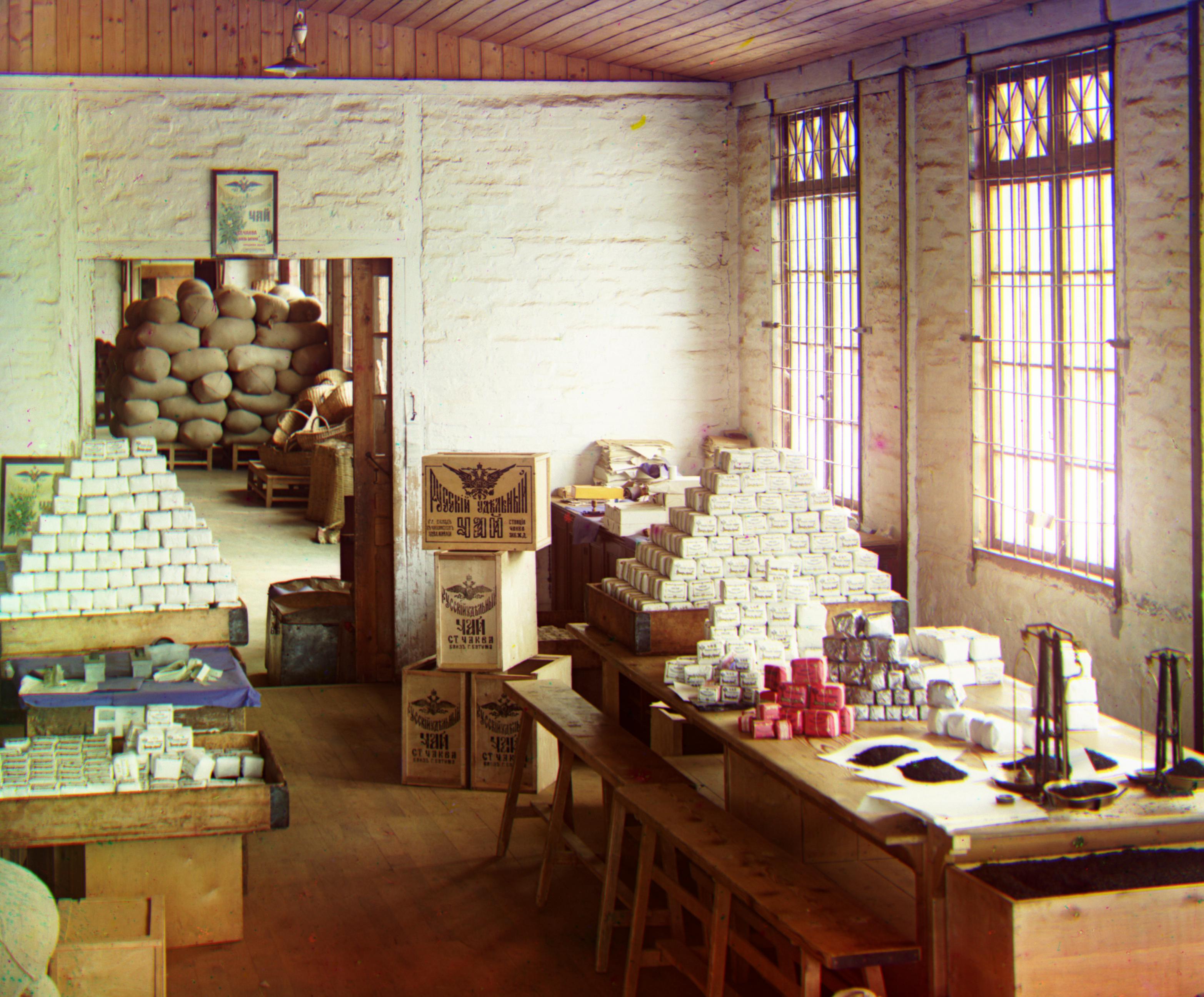
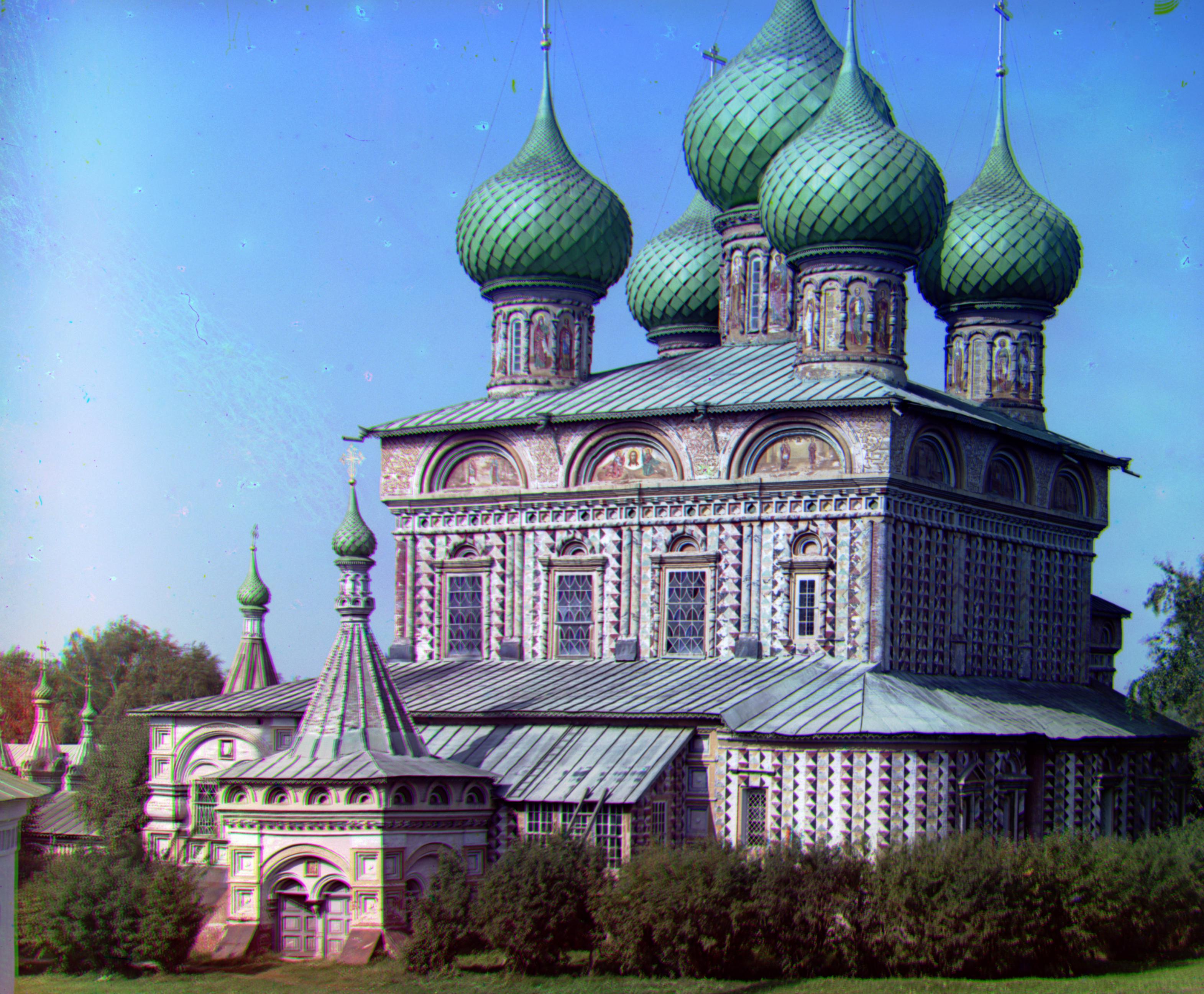
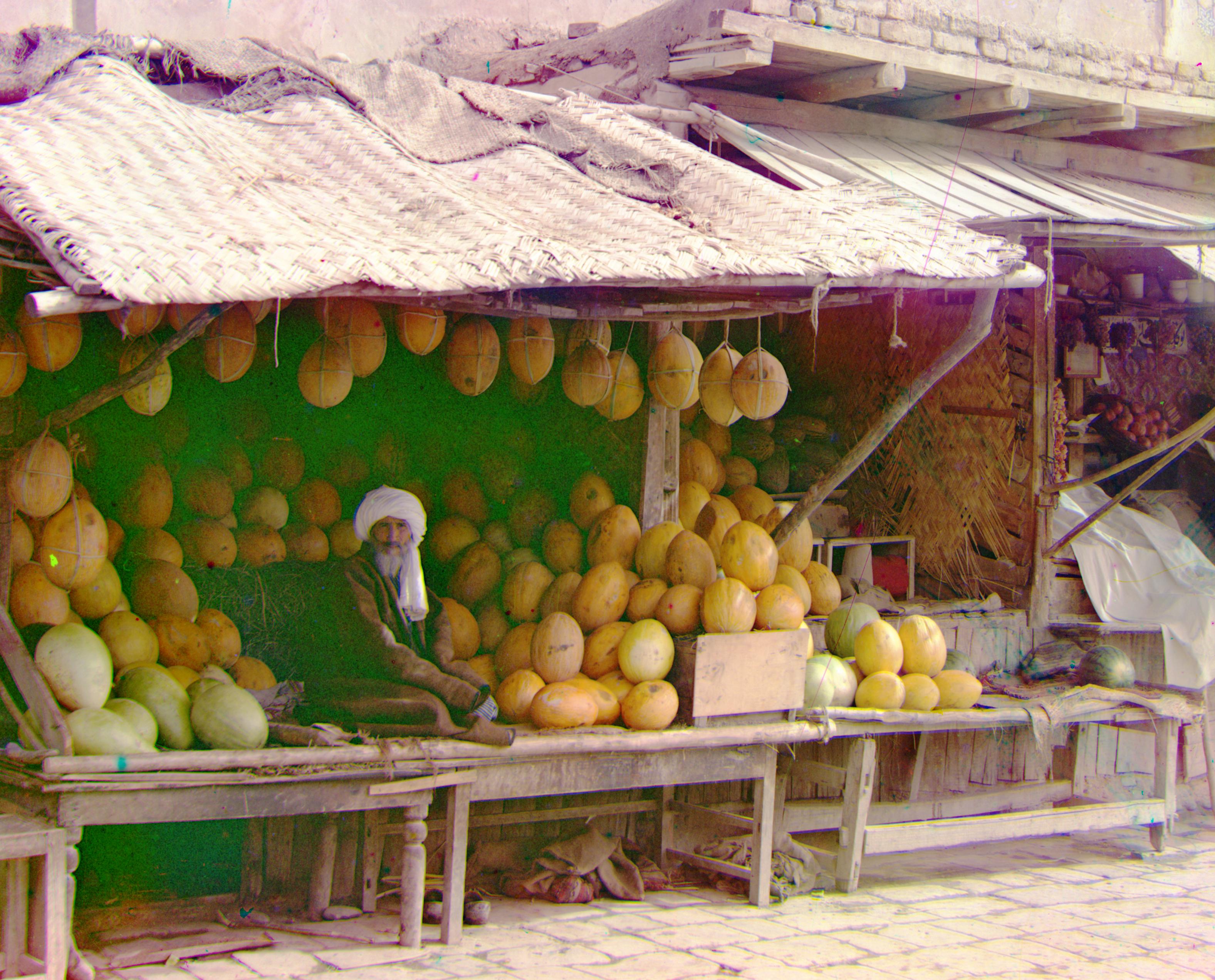
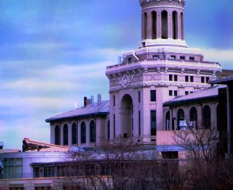
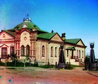
Results From workshop.tif
Without Histogram Equalization
|
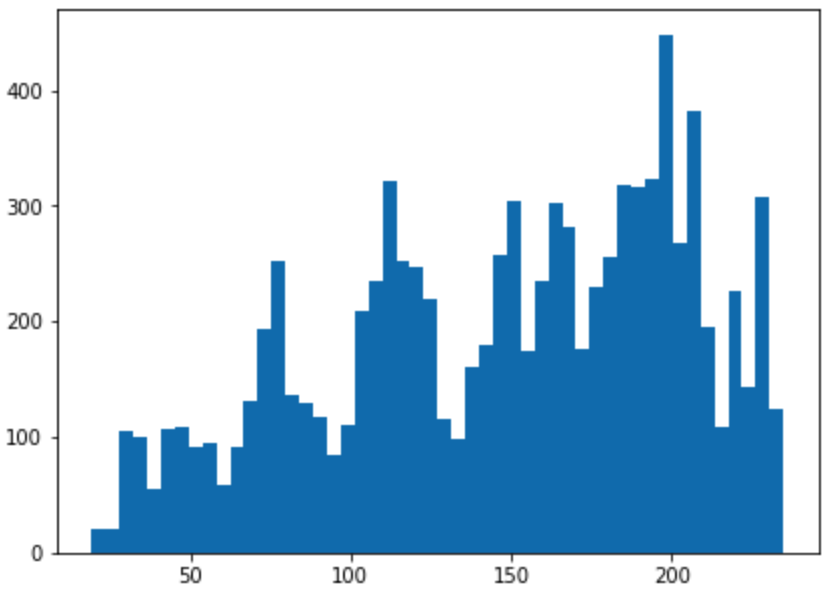
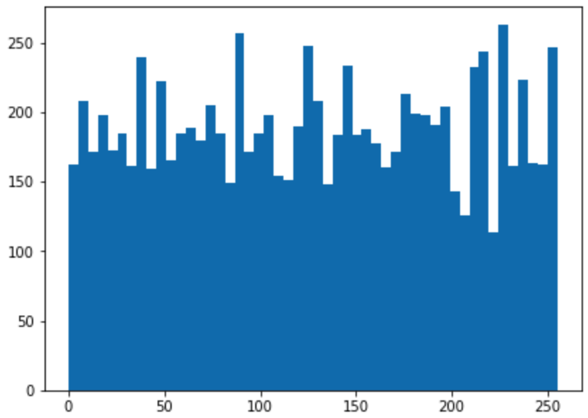
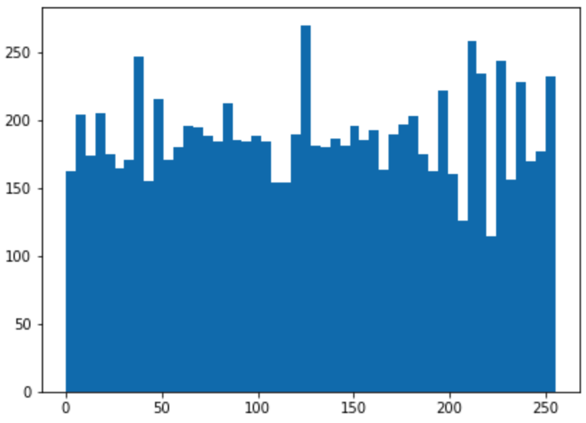
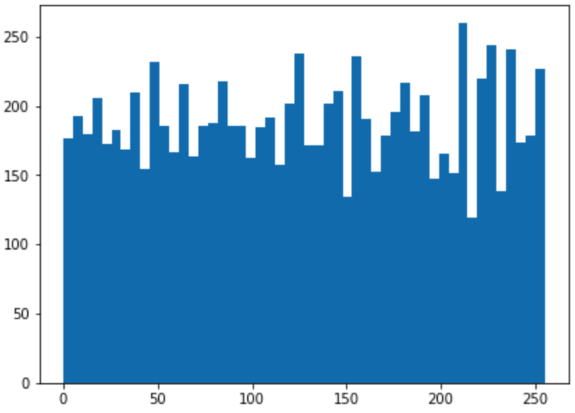
Color Channel Pixel Values Distribution(RGB)
|
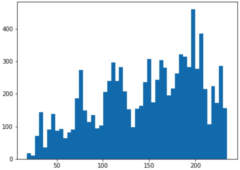
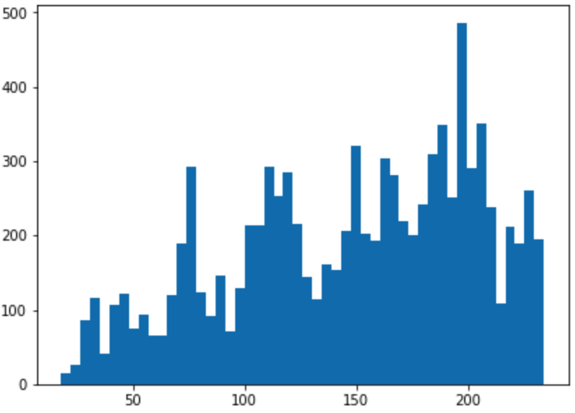
With Histogram Equalization
|
Color Channel Pixel Values Distribution(RGB)
|
In the example above, the improvement after Histogram Equalization is quite significant. The original picture lacks
contrast between the darkness and brightness, which makes it hard to see some details. For instance, the boundaries between
bricks on the left side of the image are not shown clealy in the oringinal image, while the result after Histogram Equalization
successfully makes those details visible.
Section III: Auto Image Cropping
(Bells and Whistles)
Because of channel shifting, there are areas near the edges of produced images that are not perfectly covered by all three color channels.
But using the displacement information calculated in the alignment process, we have clues about which part should be automaticly
cropped. For example, for an image, if displacement of the green channel is [-3, 6] and the red channel is [1, -5], I take the maximum
displacement on every axis both negatively and positively, which is 1 and -3 for axis 0, 6 and -5 for axis 1. Then I use this information
to crop the produced image.
Here is a demonstration of the auto image cropping.
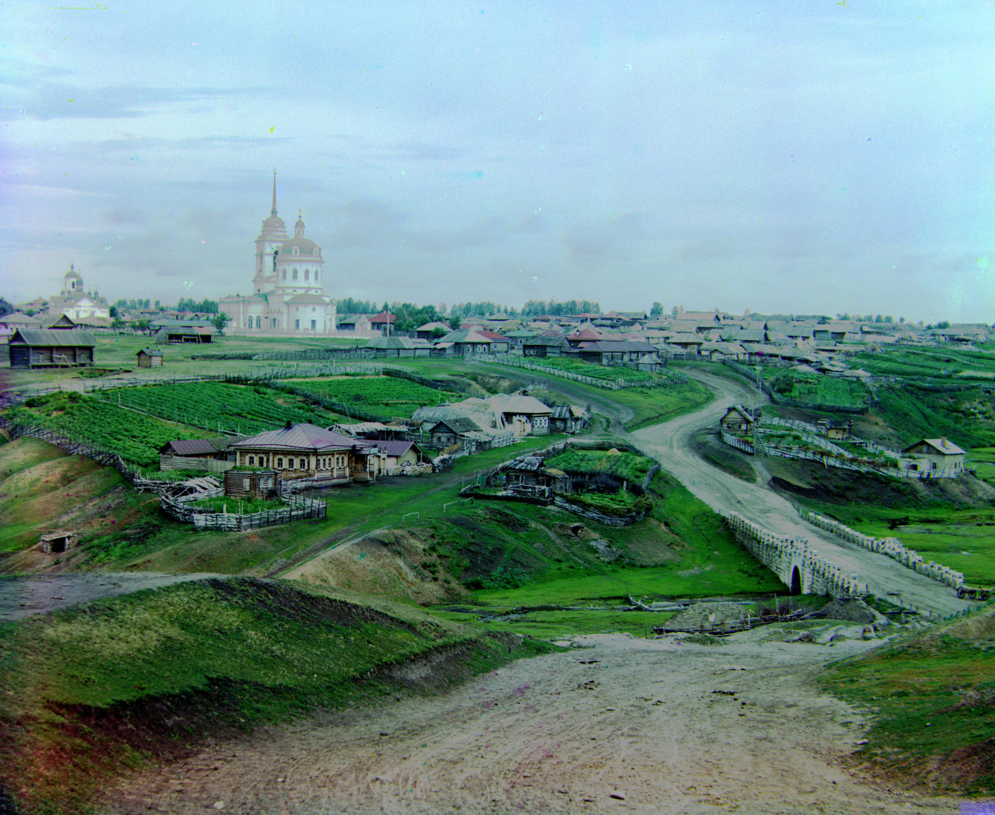
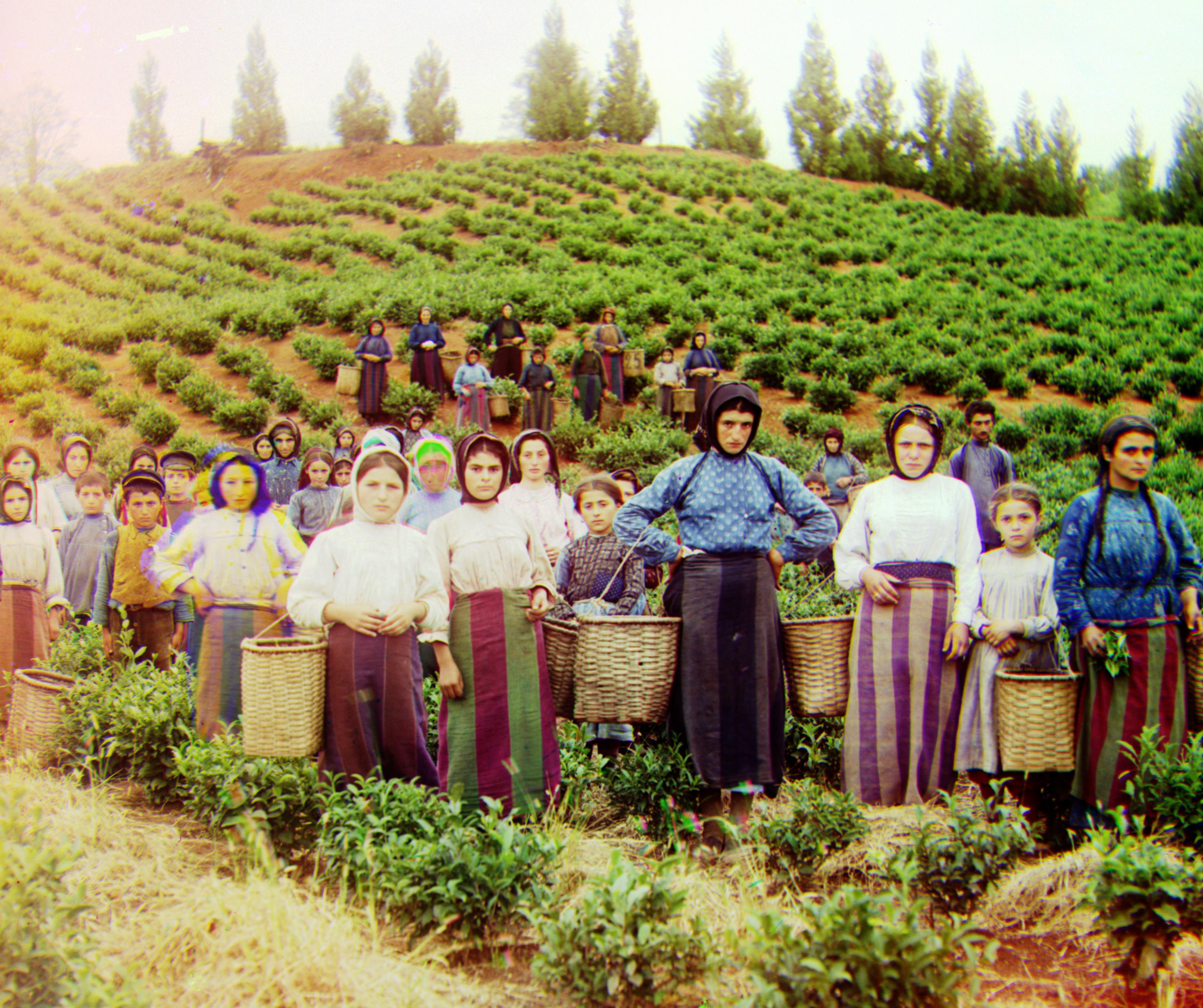
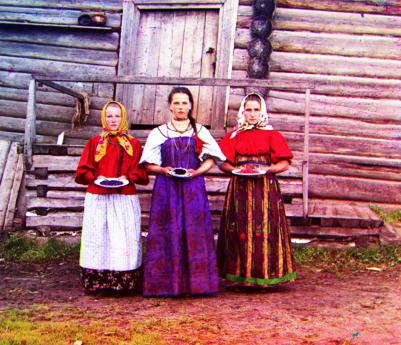
Results From harvesters.tif
With Auto Cropping

|
Without Auto Cropping
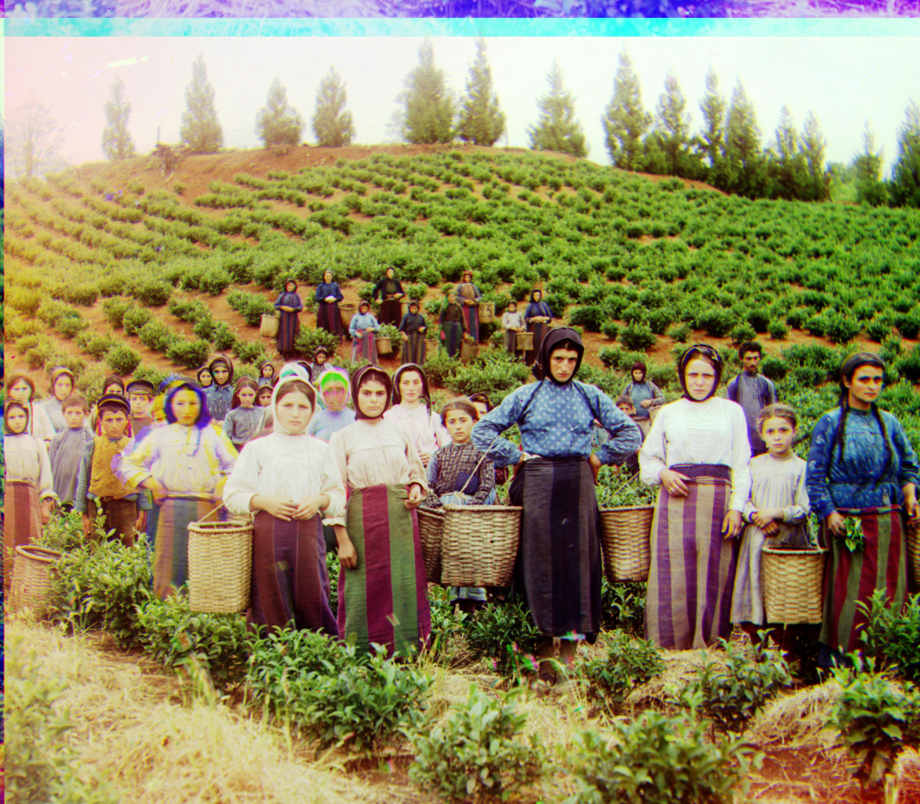
|
In the example above, the displacement of green channel is [60, 15] and displacement of red channel is [123, 12].
Therefore, 123 rows of pixels on the top edge and 15 columns of pixels on the left edge are automatically cropped.
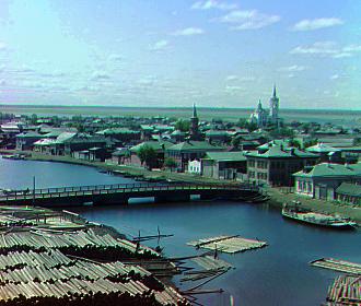
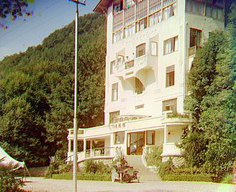
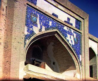
Section IV: Sample Results
 Offset: G[52,-2] R[105,-13]
|
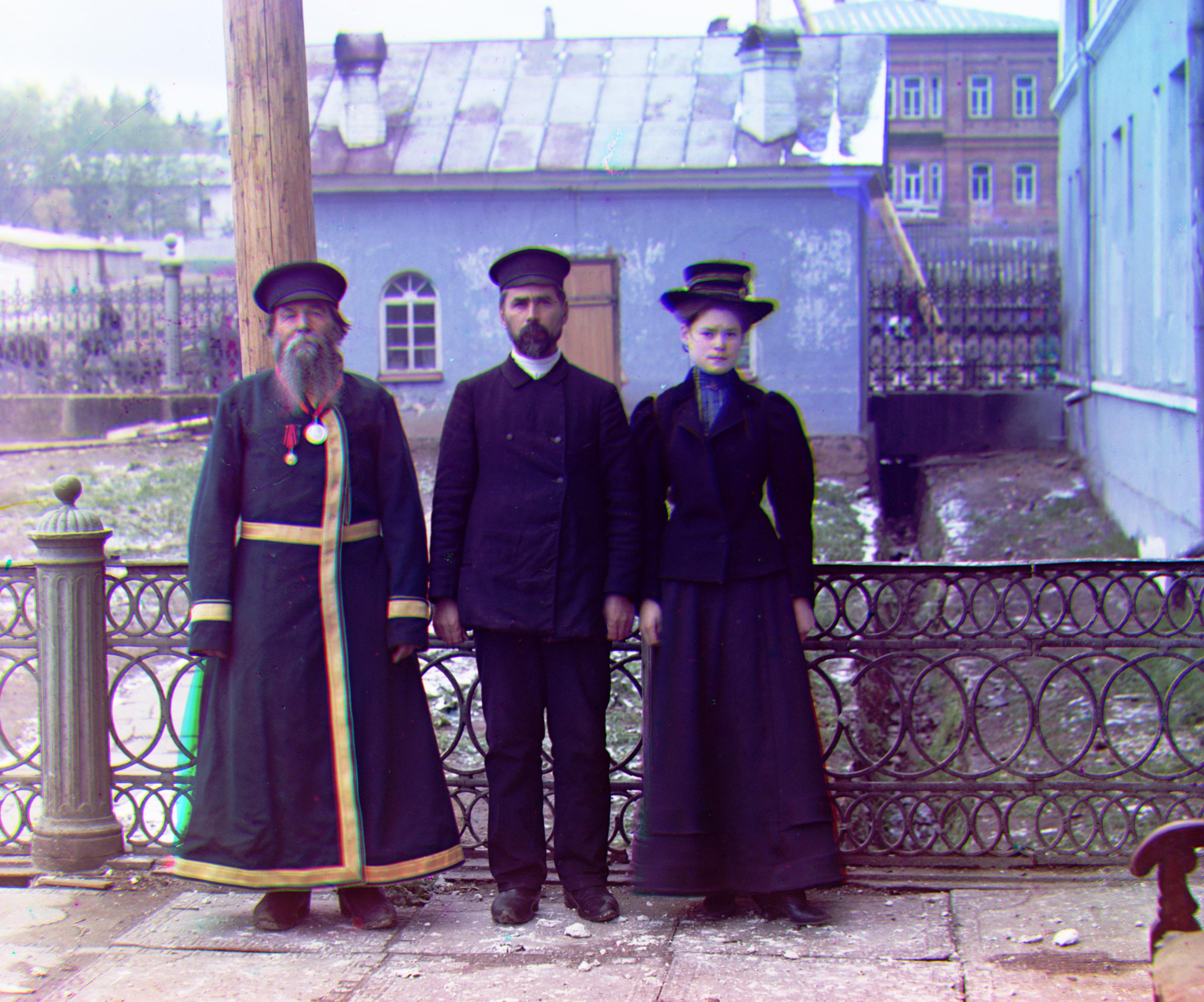
 Offset: G[41,8] R[85,29]
|
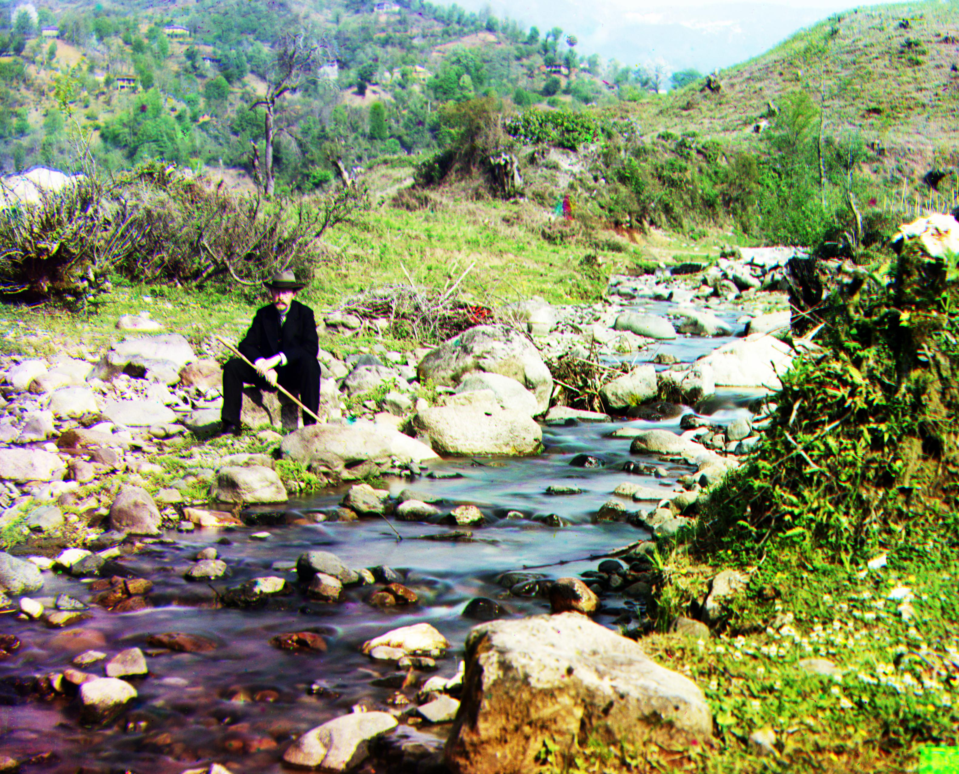
 Offset: G[40,17] R[89,23]
|
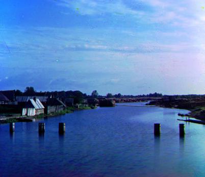
 Offset: G[57,9] R[120,13]
|
 Offset: G[51,27] R[108,35]
|
 Offset: G[49,24] R[105,42]
|
 Offset: G[65,11] R[137,22]
|
 Offset: G[60,15] R[123,12]
|
 Offset: G[-3,2] R[3,2]
|
 Offset: G[5,2] R[12,3]
|
 Offset: G[80,10] R[177,13]
|
 Offset: G[3,2] R[6,3]
|
 Offset: G[55,12] R[112,9]
|
 Offset: G[81,30] R[175,37]
|
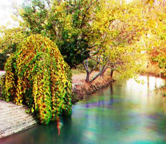
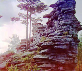
Some Extra Images
 Offset: G[1,0] R[4,1]
|
 Offset: G[-2,1] R[1,2]
|
 Offset: G[8,0] R[13,0]
|
 Offset: G[7,0] R[15,-2]
|
 Offset: G[6,2] R[14,4]
|
 Offset: G[3,3] R[4,5]
|
 Offset: G[2,3] R[5,5]
|
 Offset: G[-3,-1] R[-2,-2]
|