Cheng Cao
This part of this project is about creating an image mosiac (e.g. perspective panorama) that is formed by warping different images onto a new plane using homography calculated from matching control points between the images.
Due to the pandenmic that is spreading around, I decided to use past pictures I captured using a mirrorless camera that has been successful in creating panorama using tools like Lightroom and Photoshop. Then I created a python GUI using matplotlib to select corresponding control points between the images.
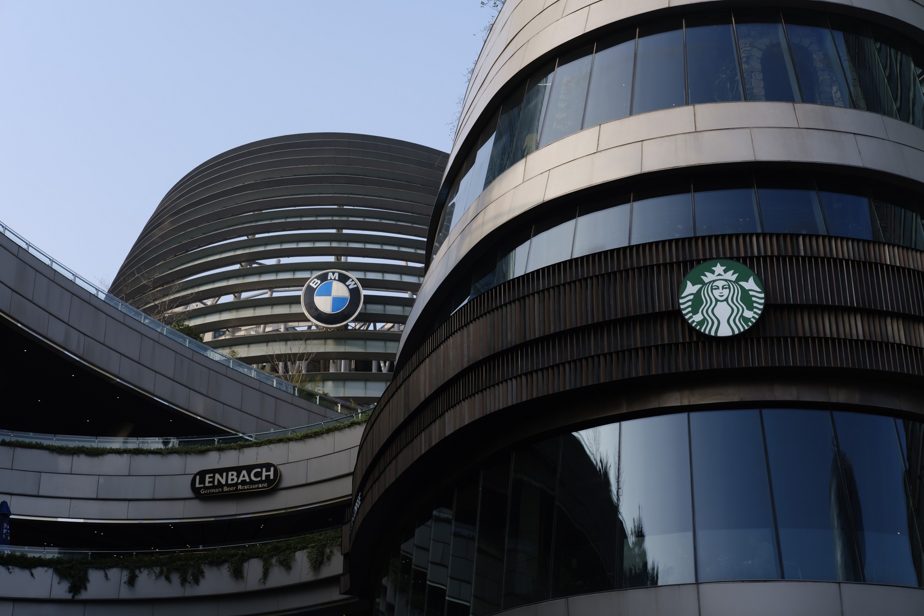
Matplotlib allows the user to zoom in and pin point a set of control points. I selected a group of corresponding control points for all the images that's going to merge. The zero-th image is served as the template and it will not be warped, while all other pictures will be morphed onto that picture.
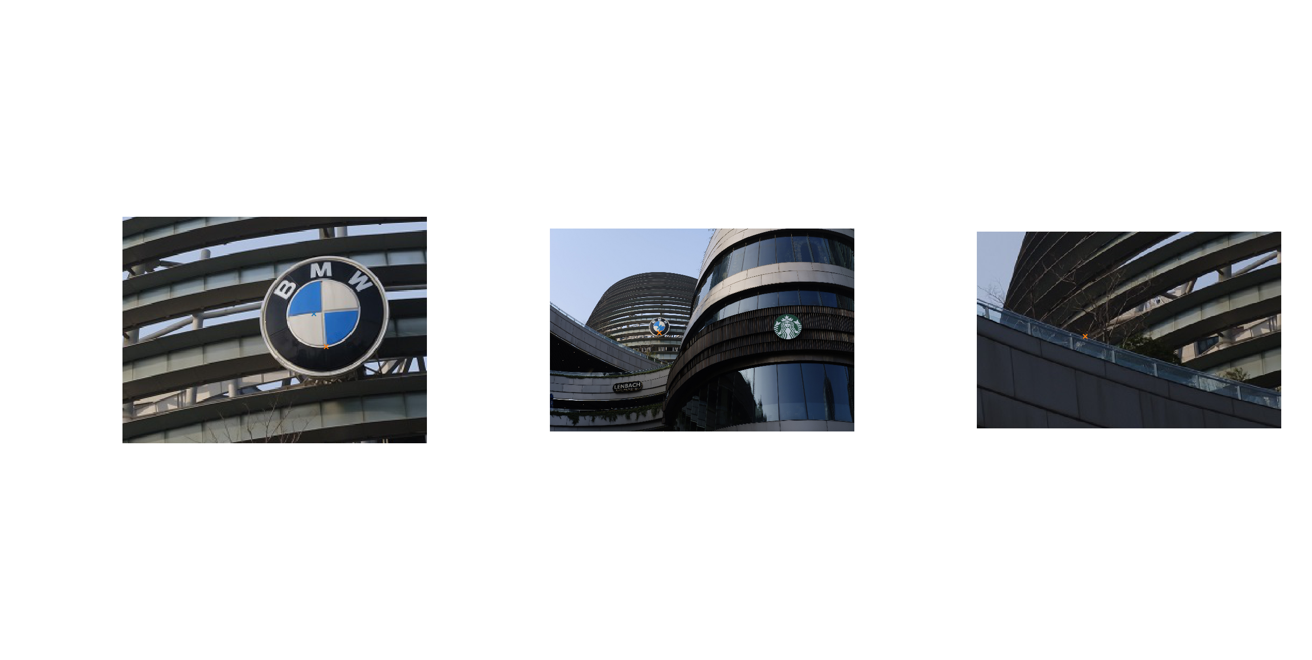
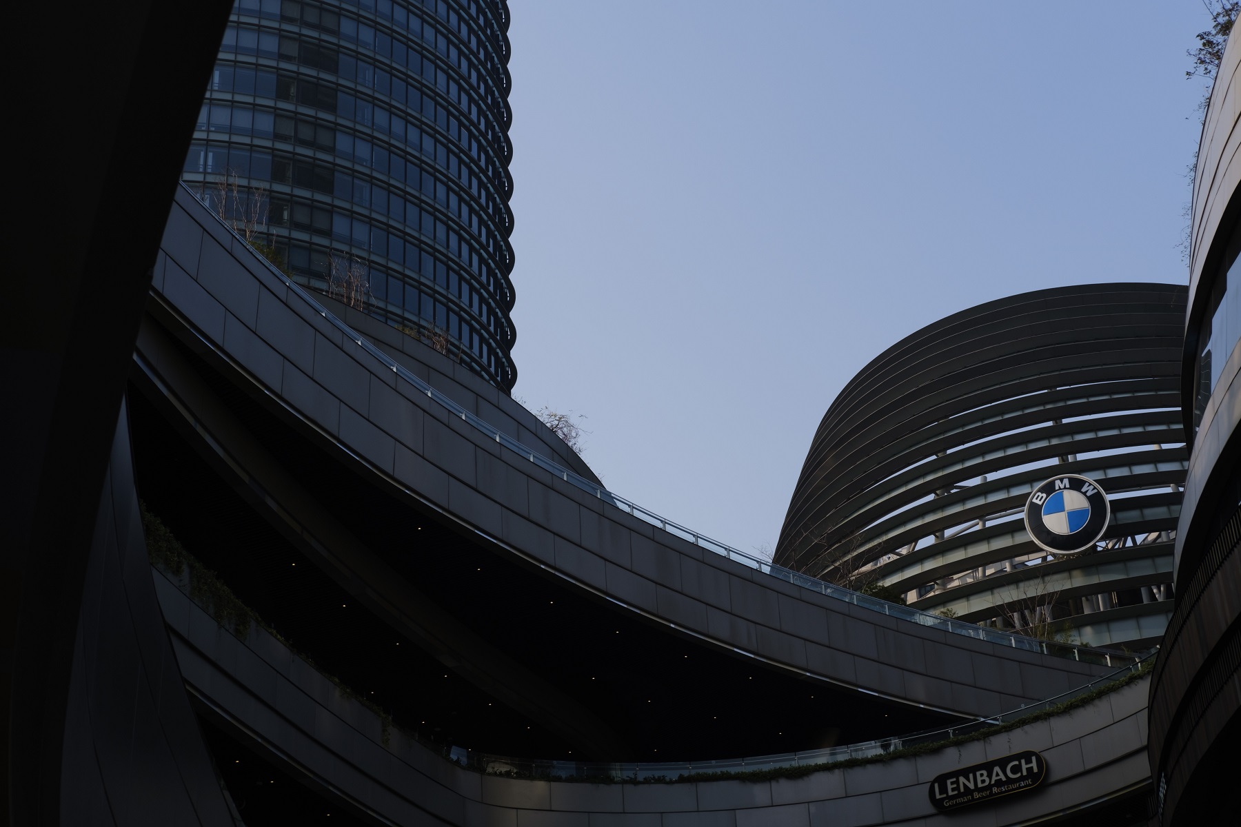
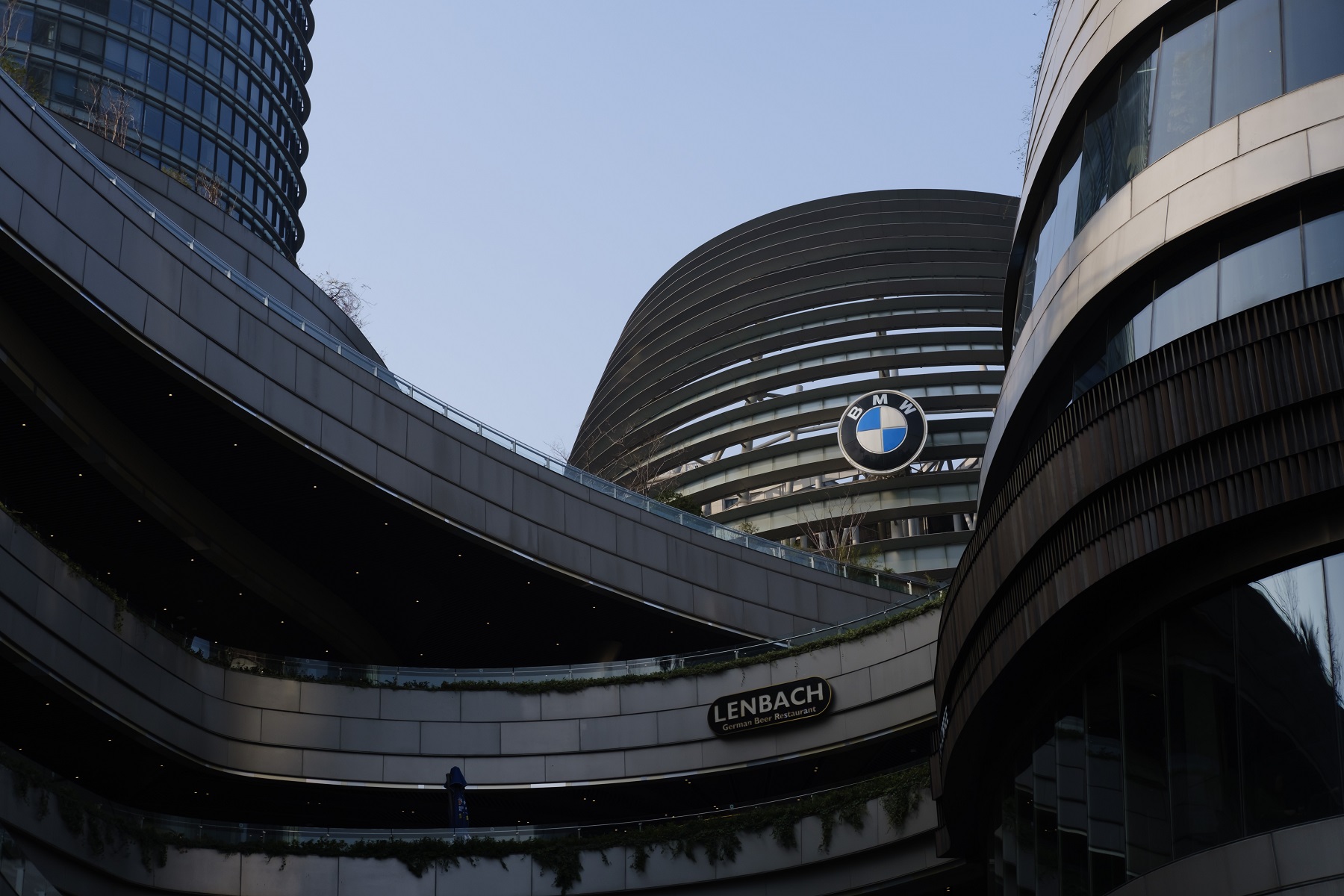
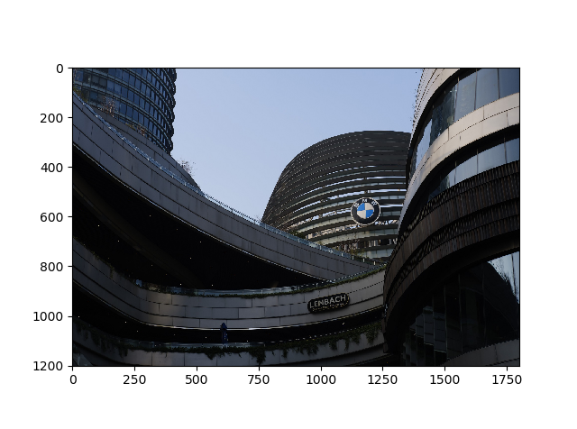
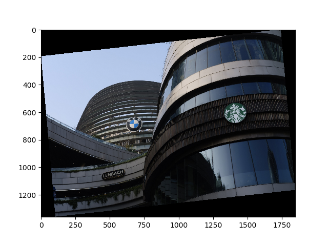
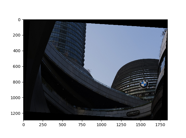
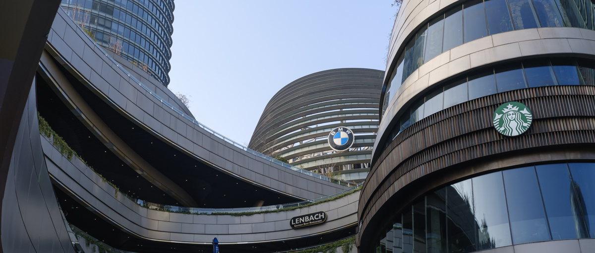
The first set of images are pictures of a modern architecture. It turned out later that these set of images have lots of flaw and would not align properlly through just homography.
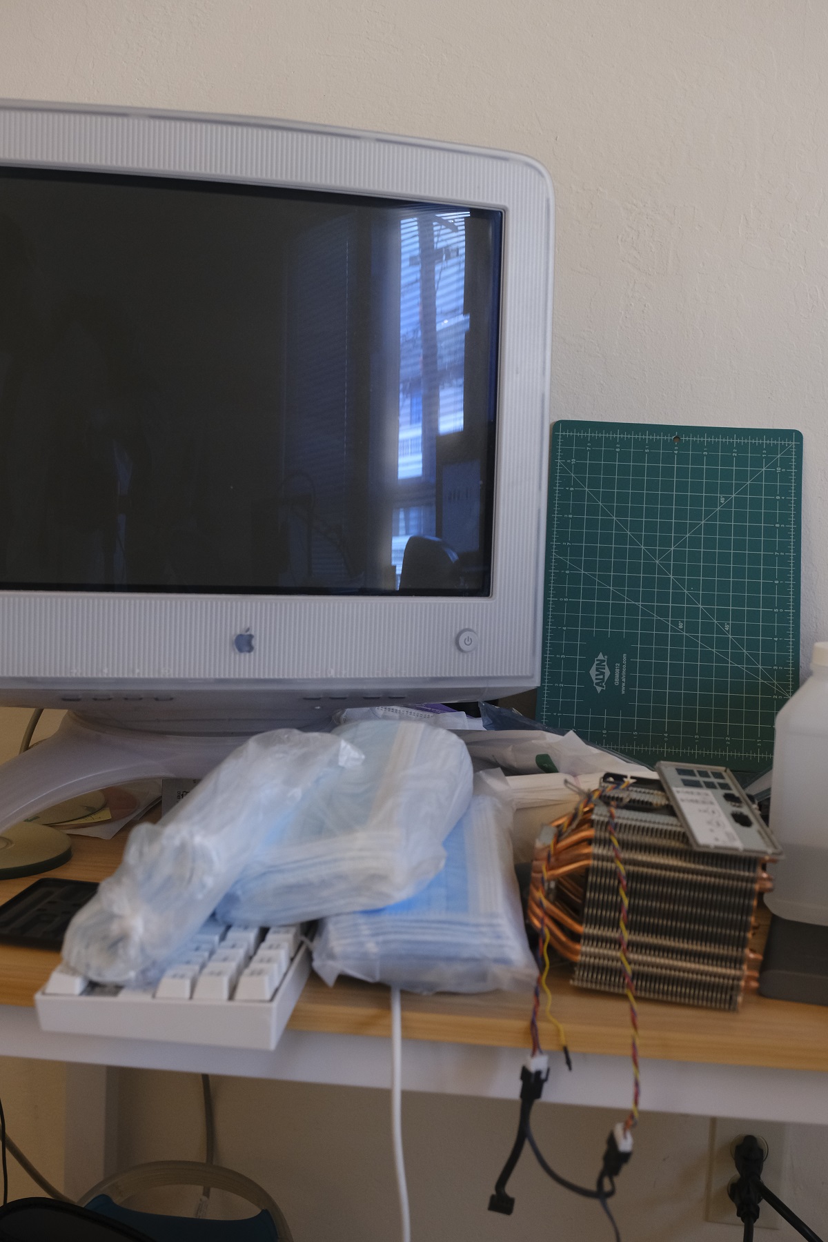
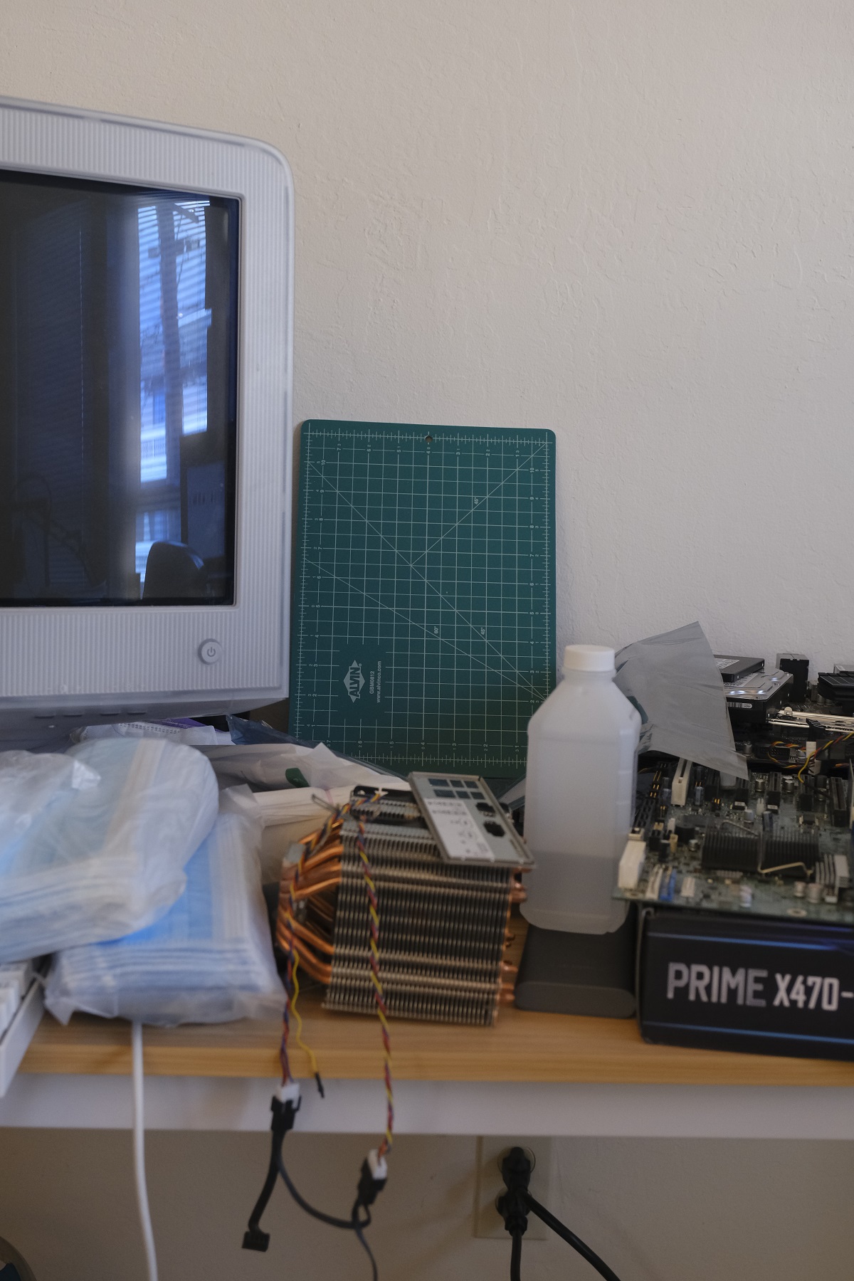
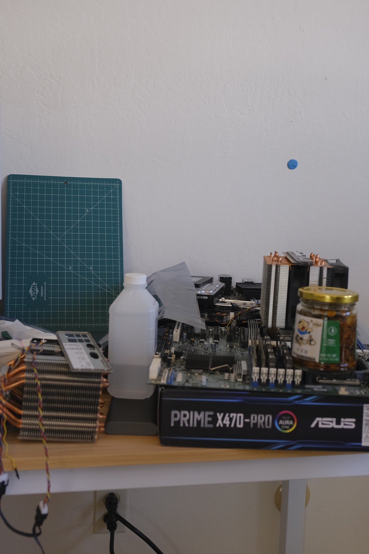
The second set of images are pictures of a CRT and a bunch or hardware.
The images' control points are used to compute the homography. The idea is to find a matrix A such that it transforms all the control points in image 1 to the corresponding control points in image 2. We can use the same matrix to warp the whole image, just like warpping each individual points. Least-square solution is used as the control points are not perfect and it's impossible to get an exact solutions for more than 4 control points (that will be eight equations availble, and the homography has 8 unknowns).
One specific tricky things in python is that the images are stored in matrices so that they are row-major indexed instead of cartesian coordinates. The coordinates passed in are actually matrix i,j coordinates and needs to be flipped to compute the homography.
A function is constructed to warp the images. If first takes in the image and constructs an interpolation function out of the image so that the image will be continous and reduces aliasing. Then the bounding box of the images are warpped using the computed homography to get the bounding box of the warpped image in the target plane. Then a buffer of the size of the bounding box is constructed and for every pixel on this buffer the color value is evaluted through the interpolation function, with their corresponding coordinates computed through homography.
This can be summarized as:
buffer = [...]
interpolated = Bilinear Interpolation (image)
Foreach pixel P in buffer
-   Coordinate in Image = Homography * Coordinate of Pixel
-   P = interpolated(Coordinate in Image)
Instead of mapping image pixels to the target plane, we do it other way around so that we are sampling a color value for each pixel in target plane. By doing this we won't have any black pixels or gaps in the warpped image (a kind of undersampling artifact). This also has better performance as it does not over-evalute pixels in over-sampled areas.
As stated before all the images are warpped onto one image (the first image in the sequence). That means that image is served as the target image plane. Here's the result of warping the three images from set 1 to the first image's plane.
Then the images are blended together using the bounding box information we get eariler when warpping the image. The images are multiplied by weight and summed into the final image. Then the final image are divdided by the summed weight. Without weighted averaging, the ghosting are very apparent and the edges of the image is pretty jarring.
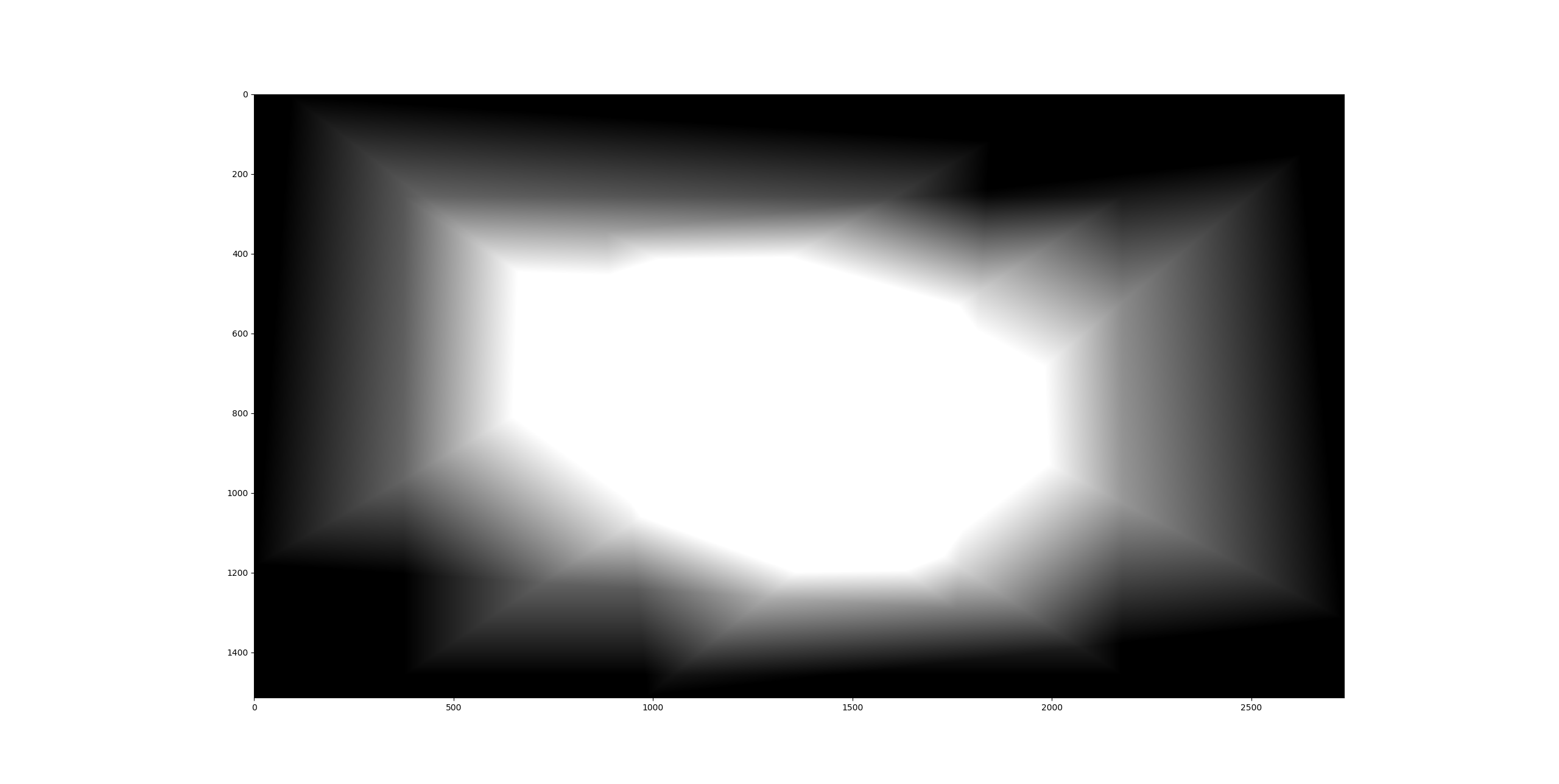
A tweak is added for better results. The images are seperated into two diffent frequency band, and the low frequency band is averged with a weight that goes linearly to zero from image center to image border to reduce artifacts. The high frequency has a very different weighting. Only the very border is eliminated as the laplacian stack breaks down near the border. The hard transition to black creates a high frequency edge and this is not something we want in the final image.
Here's the result and the weights on low frequency band for set 1. The dots are the projected control points.
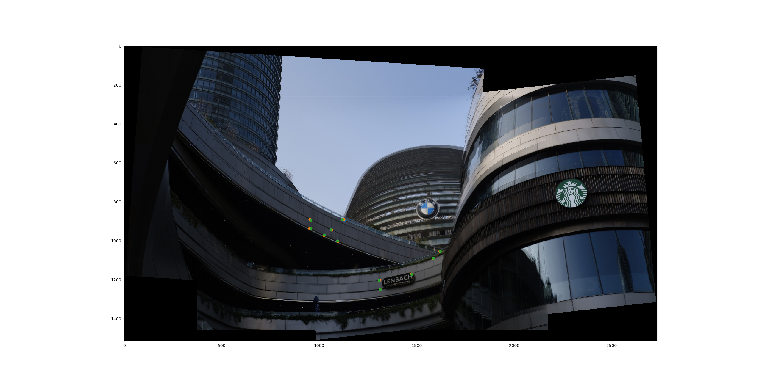
We can observe that the control points does not match exactly. This is expected behaviour as we have multiple control points and each point is not going to be precise. Moreover we can see some severe artifacting and ghosting on the background image and some of those in the foreground image. The reason could be that the images are not taken exactly with the same camera position. Some slight translations can be observed through the parallax between the foreground building and background building. Here the control points are matched on the foreground so the center curved building is mostly aligned but the background and the building on the right does not produce a good result. As these buildings are not planar at all, this is a hard problem to fix.
Here's the result for the second set:
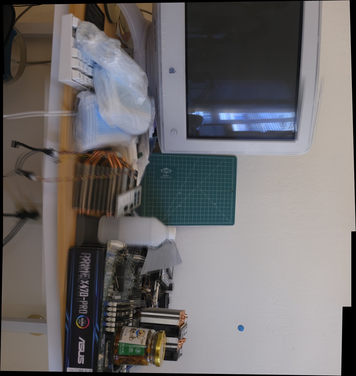
From this set we can observe there's still large deviations. After some inspection I concluded that this image is taken too close to the subject and the result of parallax is more pronounce. As the tripod does not actually guarantee that the camera is rotating on its center axis (in fact for this setup my camera is put to portrait orientation and there's pretty big translation in camera location). Also the lens has some barrow distortion and this is probably why the staight line at the bottom are not straight. I especially put a cutting pad in the scene so that it could serve as a reference plane. We can see that the cutting pad is aligned pretty well, but the control points outside the cutting pad is introducing severe noise and ghosting as they actually does not match.
This first thing I noticed is that the stark difference between my result and the result from Photoshop. It seems that Photoshop has a much more robust algorithm and it probably not only computes homography but some higher order transformation so that translation of the camera can also be handled properrly. Here's the reference result from set 1 (Clean and sharp, it's black magic from Adobe!):
If I can know the location of the camera, we can probably produce better ghosting-free results as we can construct a proper lightfield instead of just warpping images, as the images are ultimately a plane but the scene is complex and non-planar.
The technique of blending and cutting also serves an important role in this. A proper seemless cut would reduce the visual artifact by a large amount. Also blending in multiple frequency with weighted blending improves the result a lot (at least when gazing the image it looks kind of right). However upon closer insepction there's a lot of problems. Maybe in the future or next part of the project I can use some higher order transformation or a different projection to reduces the ghosting. One idea would be seperating the image into a subgrid and match the homography for each subgrid. That way the image could bare with translations and lens distortions better.
Another improvement could be made is to introduce the ability to use relative homography instead of projecting every image onto one plane at once which requires an common overlap over all images. Growing the mosiac one by one would work to some extent, however the results are unsatisfactory as the error accumulates and the panomora produced doesn't even have a level horizon, which is pretty jarring.