CS 194 - Assignment 5 - Stitching Photo Mosaics
Haoyan Huo
All the photos in this document are taken using iPhone XR and have ratio 4x3.
Table of Contents
- Part A: Image Warping and Mosaicing
- Part A.1: Identifying Homography Matrices
- Part A.2: Rectifying Surfaces using Image Warping
- Part A.3: Image Mosaicing
- Part A.3.1: Successful Examples
- Part A.3.2: Failed Example
- Part A Conclusion
- Part B: Feature Matching for Autostitching
- Part B.1: Harris Interesting Points and ANMS
- Part B.2: Feature Descriptor of Points and Feature Matching
- Part B.3: Auto image mosaicing
- Part B Conclusions
Part A: Image Warping and Mosaicing Go to TOC
Part A.1: Identifying homography matrices Go to TOC
In this part, we develop the concept of "homography", and use this concept to warp images. An image homography, is defined as a 3x3 transformation matrix that transforms points from one coordinate system to another one coordinate system: $p'=Hp$. For example, the identity transformation: $H=\mathbb{I}^{3}$.
To find homographies, one way is to define a set of correspondence points in two different coordinate systems, $\{p'\}$ and $\{p\}$, and the homography matrix $H$ can be found by using least squares: $H=\arg\min\limits_{M} \sum_{i}||p_i' - Mp_i||^2$. Note that the homography matrices only have 8 degrees of freedom: $H=[H_{11}, H_{12}, H_{13}; H_{21}, H_{22}, H_{23}; H_{31}, H_{32}, 1]$.
Once $H$ is found, we can easily transform points $q$ from one coordinate system to another one $q'=Hq$. Usually the last component of $q'$ is not 1, so we need to normalize $q'$ by the last component.
Part A.2: Rectifying surfaces using image warping Go to TOC
To warp image from one coordinate system to another one, I used inverse warping: the set of pixels are defined in the target image, and the coordinates of these pixels are transformed into the original coordinate system. Pixel values of these points are computed using interpolation methods on the original image.
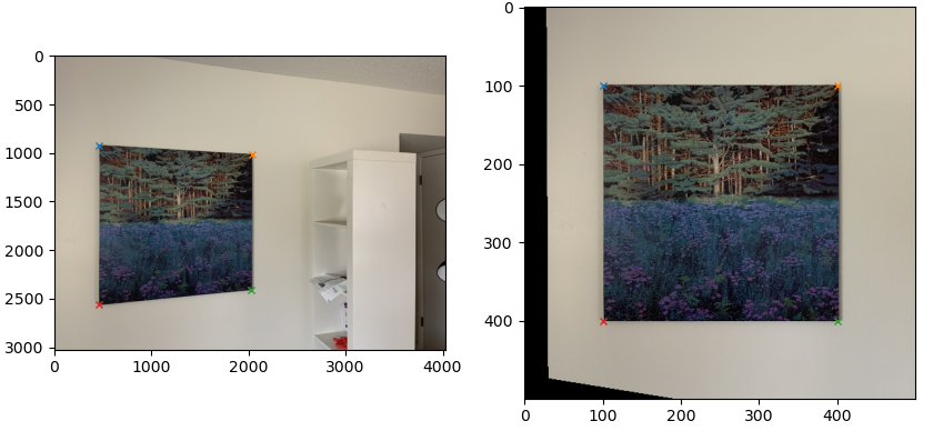
To test this method, I identified some rectangular surfaces in images, and try to find target coordinate systems where pixels are rectangular. Especially, the four corners are transformed into four fixed points: $[100, 100], [400, 100], [400, 400], [100, 400]$.
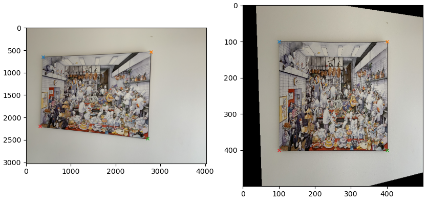
The following shows another example.
Part A.3: Image mosaicing Go to TOC
Part A.3.1: Successful examples Go to TOC
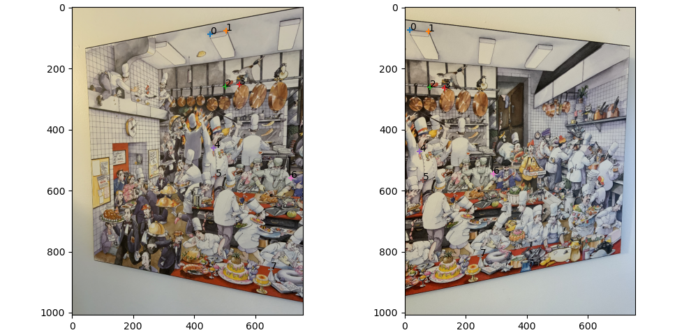
The same idea can be applied to mosaic multiple images. The mosaicing procedure can stitch different images of a same object together to create "panoramas". To do this, I selected several points of same objects on different images (as shown in the following image), and warp all images into the coordinate system of the first image.
The resulting mosaic image are created by averaging every pixel of two images. The average is weighted by the alpha value, which is set to 1 if the pixel can be found in the original image, and 0 otherwise.
Another example:
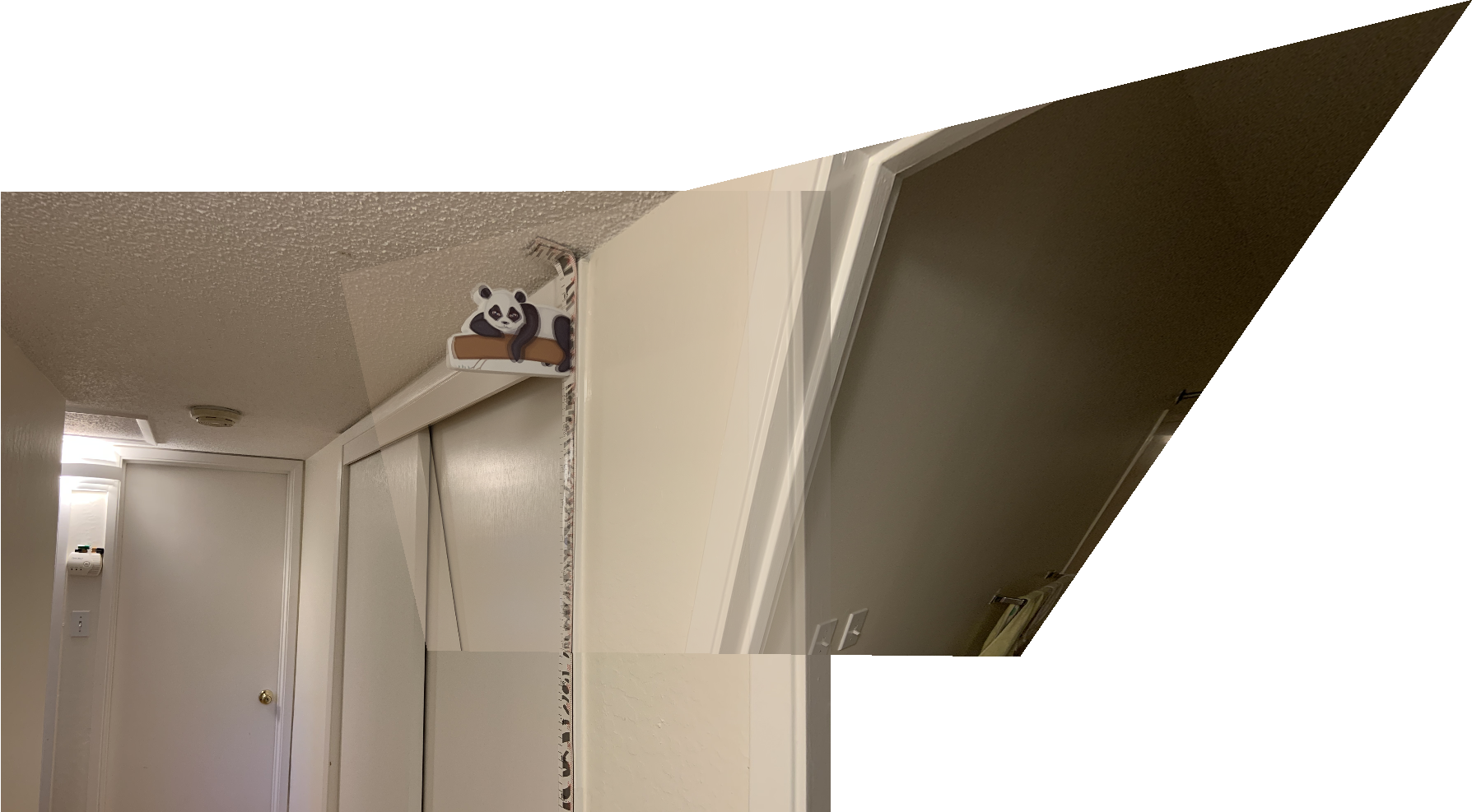
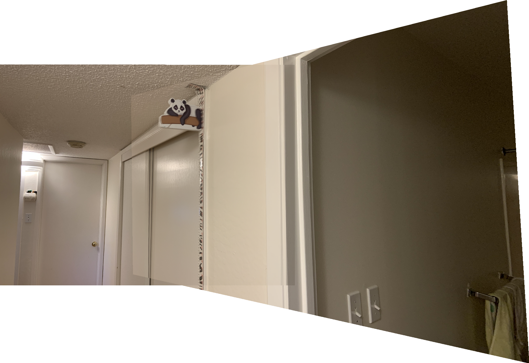
Part A.3.2: Failed example Go to TOC
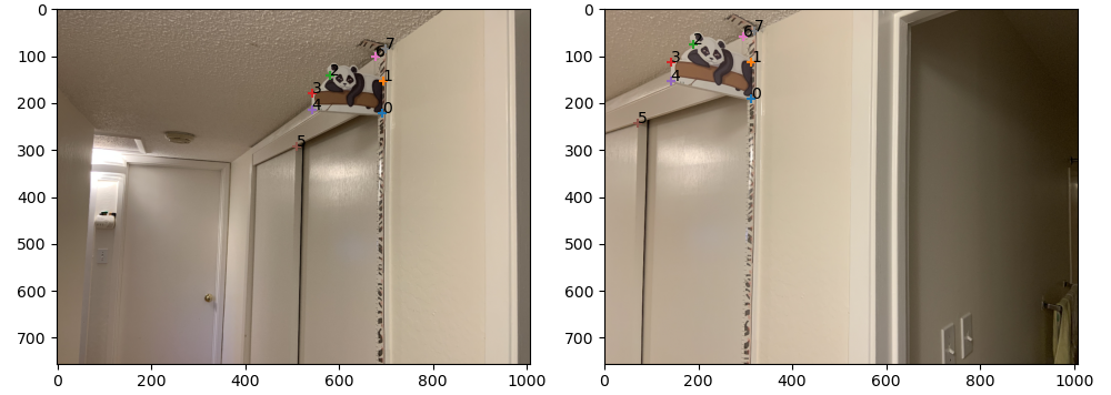
Finally, we show one more example where two images failed to be stitched together. I think the reason is because the points are only chosen around a small area (around the toy panda). In this case, the regions around the panda is stitched well, however the homography matrix has a large variance in regions far from the panda, as suggested by the serious mismatch of the door.
Part A Conclusion Go to TOC
I learned from part A how to transform images taking at different places into a common coordinate system. Since there might exist noise, distortion and other artifacts in the photo taking process, the implementation of least squares for homography matrices is crucial. However, as we have learned from ML courses, any estimation models have a trade-off between bias and variance, as in the last example of photo mosaicing. Thus, to reduce this variance, we need to prepare a good low-bias training data (correspondence points).
Part B: Feature Matching for Autostitching Go to TOC
This part implements most algorithms in the paper "Multi-Image Matching using Multi-Scale Oriented Patches" by Brown et al.
Part B.1: Harris Interest Points and ANMS Go to TOC
Harris corner points are features of an image computed using edge-detection-like techniques. Usually, Harris corner points are related with edges of the image or sudden changes of pixel brightness. To find Harris corner points, we have to first convert the color image into an gray scale image. Then the Harris corner points can be obtained by applying corresponding image filters and thresholding gradient changes. The following figure shows an example run of Harris corners detector.

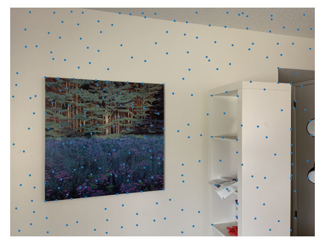
As you can see, most points of the Harris corner points are not that "interesting". To filter out those un-interesting points, we use Adaptive Non-Maximal Suppression (ANMS) to eliminate points that have low corner strengths. The following figure shows an example run of ANMS that keeps 250 interesting points. We can see that points on clean surfaces are reduced very much, but the points at edges are kept because they have large corner strengths.
Part B.2: Feature Descriptor of Points and Feature Matching Go to TOC
To find corresponding points, we need to assign certain "features" to each point and then do a comparison between points in two images. Here, we extract 8x8 patches centered around the Harris corner points and then modify (bias and gain) it to be intensity invariant. The patches are extracted in a lower resolution image (resolution scaled down by 8, instead of 5 in the original paper, because I have high-resolution images). The lower resolution image is created by performing Gaussian pyramids, as in previous projects. The following figure shows three such patches.

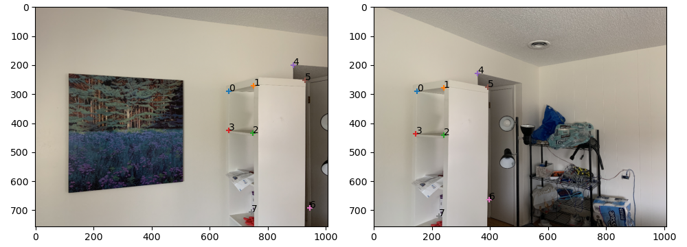
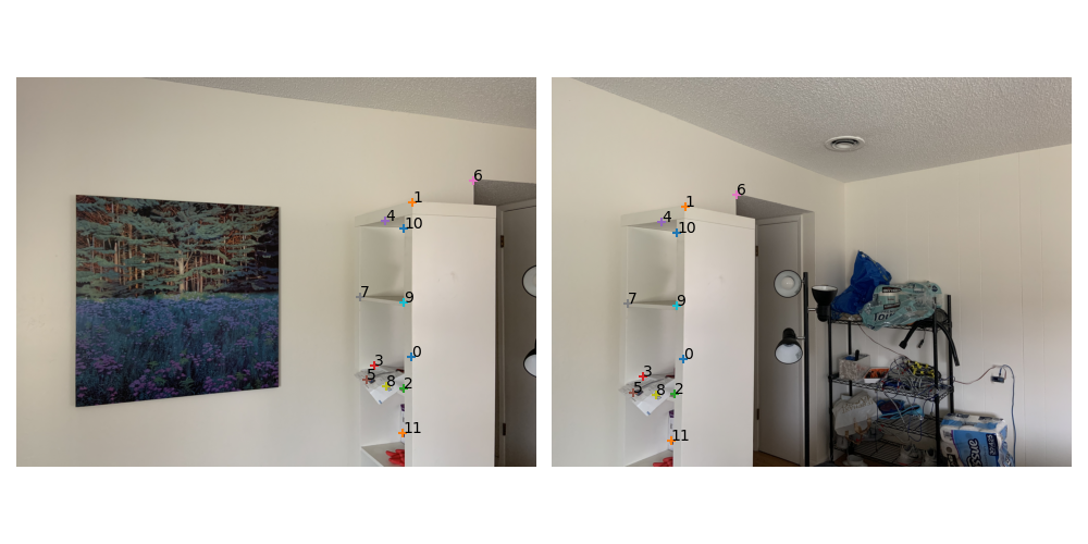
To match points in two images, we can compute the SSD between the patches of each possible correspondence point pair. According to the original paper, I used the criterion due to Lowe that requires the SSD ratio between 1st neighbor and 2nd neighbor to be less than 0.6. Then, the correspondence list is further refined using the RANSAC algorithm. An example of the correspondence points generated in this way is shown below.
Part B.3: Auto Image Mosaicing Go to TOC
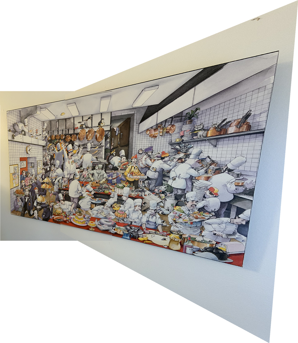
Finally, we can run the algorithm combined with Part A to generate auto image mosaicing. Below I show the three examples (left images are manually generated), alongside with the result that uses manual annotations (auto generated images are at right side). Click on each image to enlarge it.
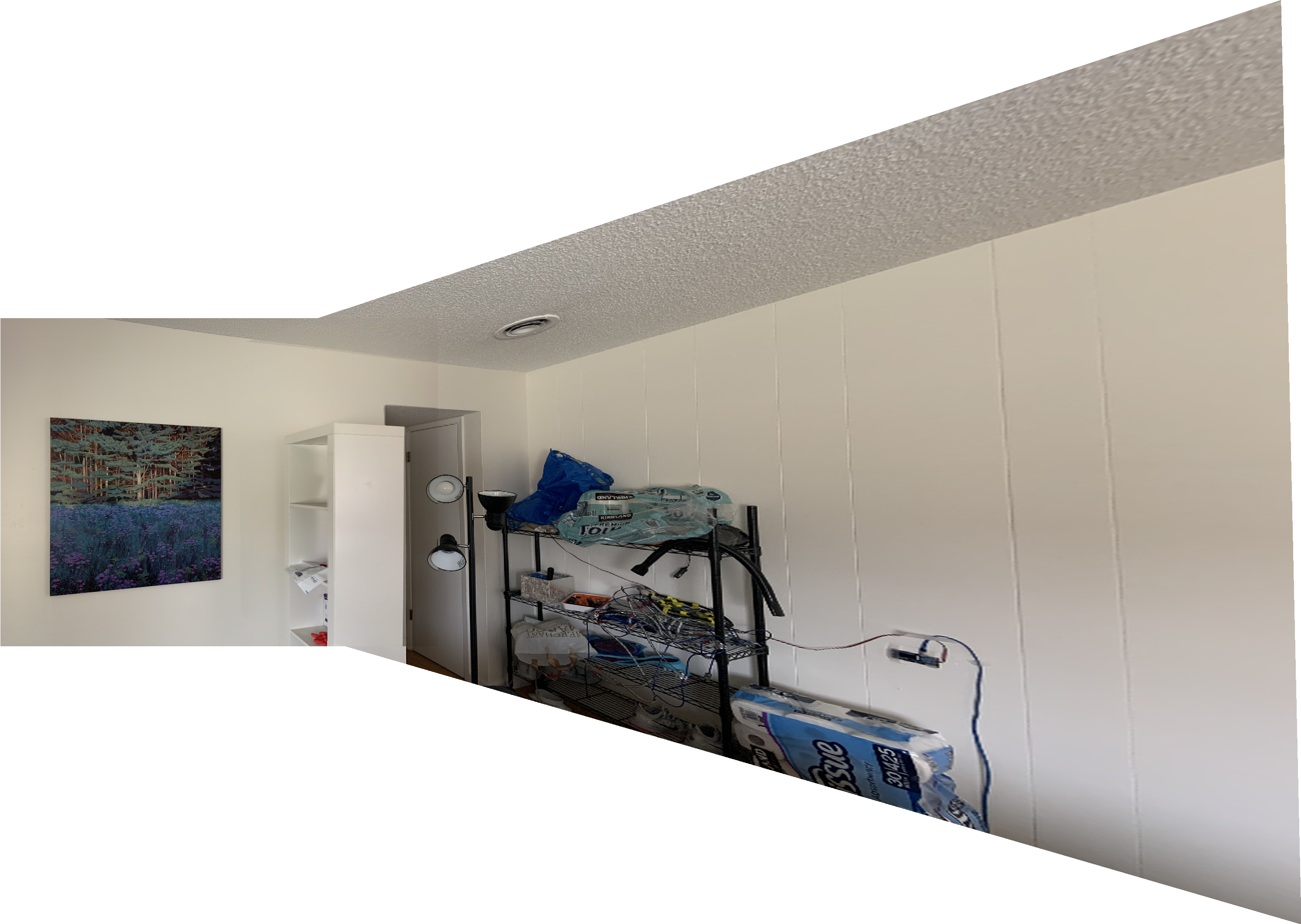
In the above image, the auto-generated result is better, because as you can see, the vertical textures on the wall are parallel with the painting frame. However, in the manually generated mosaicing, these lines are not parallel.
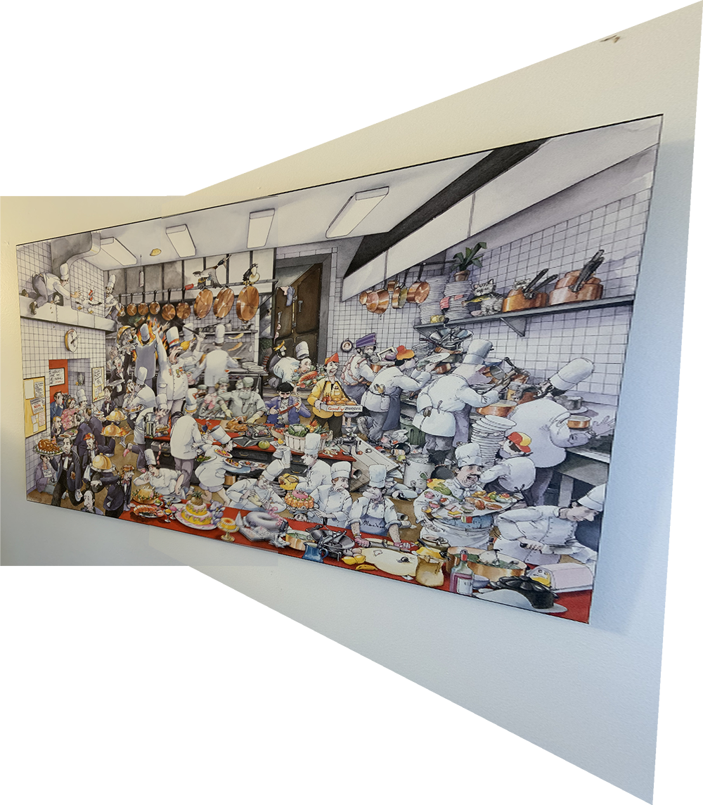
In the second example, the auto-generated result is much better, because the correspondence points cover all regions, while the manually annotated correspondence points only cover a small region, thus having large variance.
For the final image, there is no obvious difference between manually generated and auto generated result. The painting frames in the auto generated result seems to mis-align with each other. However, if you zoom in, you can see the painting details in the manually generated result seem to mis-align more. I think this result is due to that auto generated correspondence points are mostly on details, while I manually chose frame edges as correspondence points.
Part B Conclusion Go to TOC
By doing project 5B, I learned a ton of methods for extracting features from images. At first sight, the Harris corners seem to be rather random and not intuitive at all. However, by implementing ANMS and RANSAC, we significantly reduces false positives and greatly improves the quality of the correspondence points list. I think this is reasonable, as the first lessons learned in ML courses tell us feature engineering is very important for the problem to be solved.
Bells and Whistles Go to TOC
BW1: Multiscale feature extraction Go to TOC
The features of Harris corner points are extracted from different levels in a Gaussian pyramid. This is easily done by repeatedly scaling down the input image and extracting Harris corner points and features at each level. However, during my experiment I found that this method did not improve the results very much. I guess it is due to that I tuned the hyper-parameters of Harris corner/ANMS/RANSAC too much, so these parameters do not work for different levels. However, I believe this can improve the results if I have the time to tweak hyper-parameter for different image resolutions.
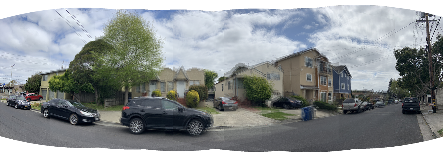
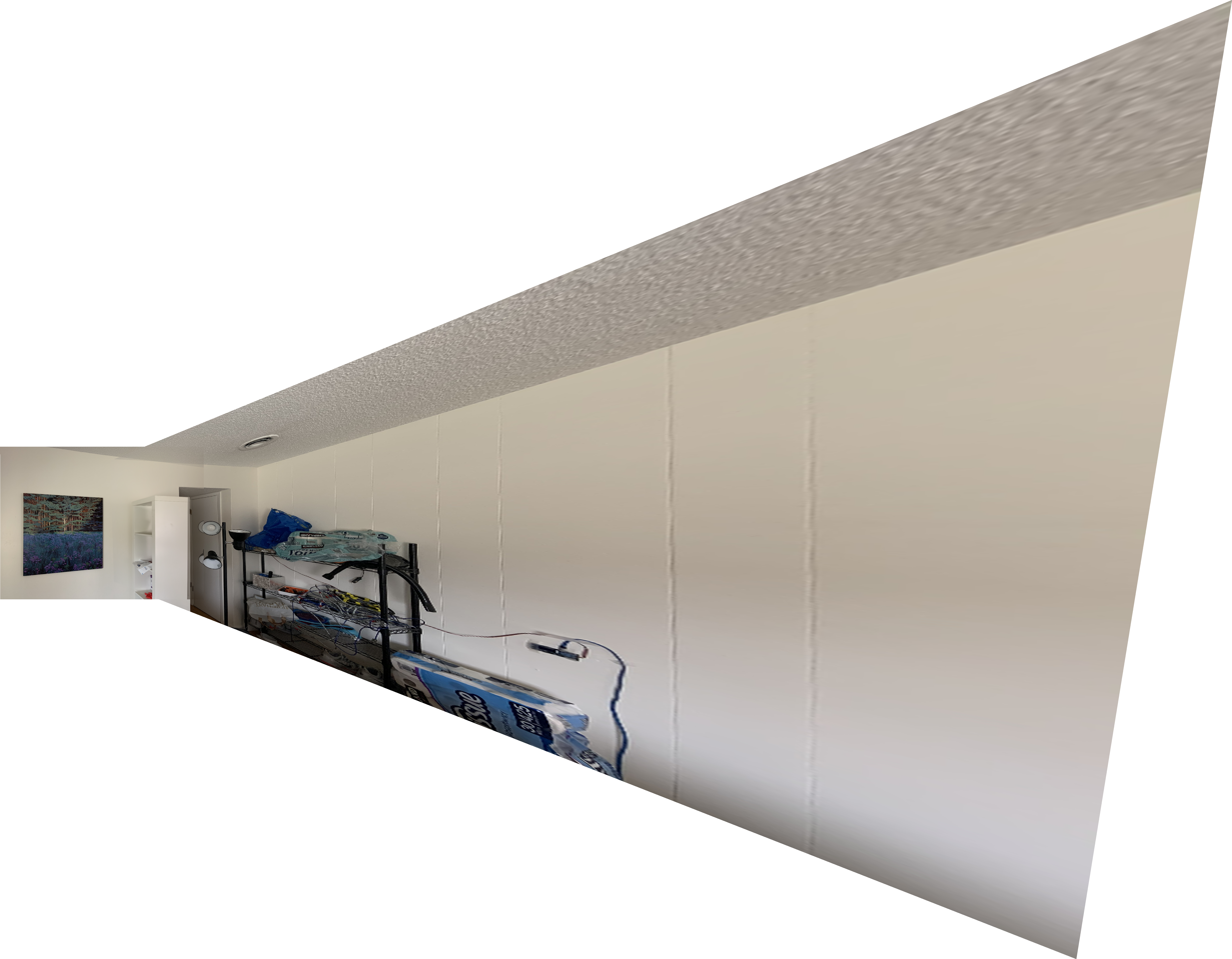
BW2: Autostitching of Panorama Go to TOC
To create panorama images, it is necessary to convert images to cylindrical coordinates. By the conversion rules learned from the class, images are first converted to cylindrical coordinate. The following are just two examples.
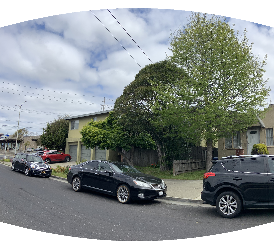
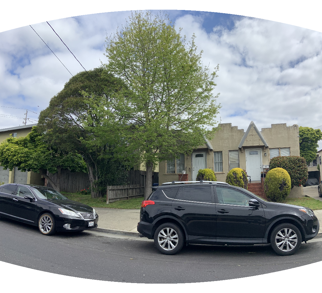
Now I tried to warp all images, and use the above auto stitching process to warp every image onto the same canvas (using translation only homographies). Using this process, we can get a very nice wide field of view. However, I noticed that the overlapped regions of images have serious mismatches. I suspect this is because I need to fix for camera radial distortions. Another reason might be that my hand shaked too much when taking these photos, so the configuration of the camera is not exactly the same.