


Texture synthesis is the creation of a larger texture image from a small sample. If you've ever used the clone tool in Adobe Photoshop, you've seen variations of some of this work applied. There are a variety of use cases for texture synthesis, from extrapolating backgrounds to creating more detailed image samples. We'll dive into how techniques like template matching, seam detection & creation, and masking are used together to create smooth, realistic sampled textures.
The techniques implemented here are based on this 2001 research paper by Efros and Freeman.
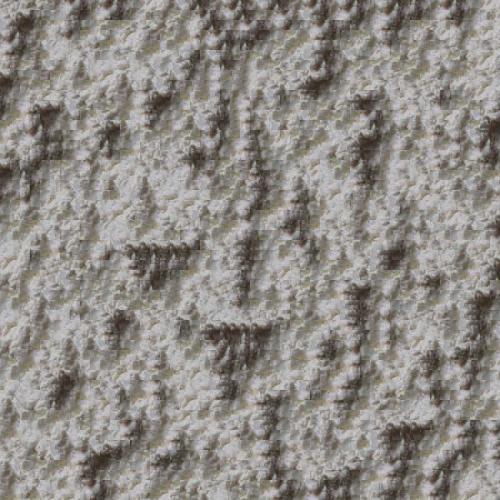
Let's start out with a sample texture which we want to "create more of".

One naive method of texture synthesis involves selecting random patches of a specified size from the source image, and laying them next to one another to form an output image of a specified size. For most source image types, the results will appear quite choppy. Here's an example with 30px by 30px randomly sampled source patches:

One way we can improve this is by trying to put "similar" looking patches next to one another, with a slight overlap between them. We can lay a patch down, then repeatedly sample patches from the source image many times, choosing the one that "fits" the previous patch the best, kind of like a puzzle. Doing this many times - on the order of several hundred random samples per best match, we can get quality results that don't require us to search the image for a similar adjacent patch each time.
We can measure how good of a match two patches are by calculating the similarity between their overlap region - using SSD, or sum of squared differences, error.
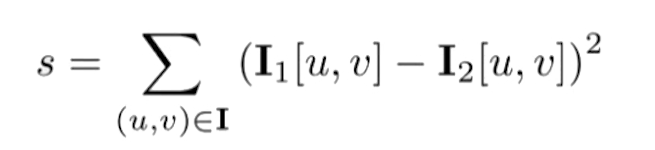
Where I1 and I2 are the respective two images whose similarities are being compared, and each (u, v) combination represents a pair of image pixel coordinates.
It's important to note that for most patches that we add to our output synthesized texture, there will be both a horizontal and vertical overlap region - in this case we find the patch which minimizes the sum of both SSD errors. Here's how it looks once again with 30px by 30px sampled patches and an 8 pixel overlap between patches.

The results with the overlap and best match approach fare a lot better, but there are still some clear artifacts. Although the most similar adjacent patch is found, the fact that square patches are stitched next to each another with an overlap repeatedly becomes visible. This makes the texture look "fake" - you can see some vertical and horizontal image edges.
As described in the 2001 SIGGRAPH paper referenced above, instead of just placing overlapping patches down parallel to each another, we can compute the best seam within an overlap along which the images should be stitched. Using a seam carving dynamic programming algorithm and building directly off the previous method of finding the best match and overlapping sampled patches - we will change how exactly we stitch together adjacent patches.
A quick summary of the progression of our stitching methods, from random, to overlap and now to stitching alongst the minimum error boundary cut.

Our goal is to compute the minimum cost seam along the overlap region, where again the cost is defined as the SSD error between the overlap regions of adjacent patches. We can compute the minimum cost path along the seam by using the following recurrence:

where E(i, j) is the minimum cost of all seam-cut paths ending at coordinates i, j and e(i, j) is the SSD error between pixel location (i, j) between the images.
Let's walk through what it looks like to stitch together two adjacent sampled texture patches using the min error boundary cut. We start out with our two patches and their corresponding overlap regions.


Now we can compute the SSD error matrix between the patch overlaps, and use the seam-stitching recurrence stated above earlier to find the minimum error cut boundary mask and visualize it.


Multiplying the mask by the left overlap, and multiplying the reverse of the mask by the right overlap, we can stitch together the two patches.


We can then repeat this stitching process continuously to form an output synthesized texture of any size.
There's a clear difference between the randomly sampled synthesized textures as compared to the overlap ones and min error boundary cut ones. However, if you look closely and zoom into the images, there are noticeable edge artifacts in the best-match & overlap created textures.
However, with the results for the best-match & min error boundary cut, in the right column, nearly all of these artifacts are smoothed out to form more natural curves and intersections between the sampled patches of the image.


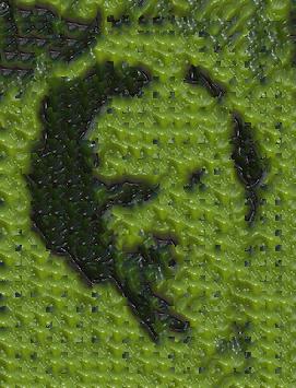
Texture transfer is giving an object the appearance of having the same texture as a sample while preserving its basic shape. We can actually use much of the work we already did while developing texture synthesis for texture transfer. We will have one input texture, and input correspondence map image, or target image (what we are trying to replicate using the texture).
The only significant thing we need to change from our texture synthesis algorithm is our cost function for choosing new overlapping patches. We can define some hyperparameter alpha and adjust our cost function to be:
where the SSD error term multiplied by alpha is the same error function from texture synthesis, patch_sampled is the current potential adjacent patch
being looked at, and patch_target is the patch in the target image at the same location in our output texture transfer image.
As mentioned in the referenced paper, the alpha parameter determines the tradeoff between the texture synthesis and the fidelity to the target image correspondence map. The closer alpha is to 1, the more we revert back to a random texture sythesis algorithm, and the closer alpha is to 0, the more our texture transfer output will look like the corresponding target image.


The results of texture transfer were very satisfying, and playing around with the hyperparameters to try to barely make the target image either appear or barely be present as fun. This project involved quite a few edge cases in getting overlapping patches to properly lay on top of one another - especially at the boundaries of the target image template. I also ended up adding an additional weight parameter for the texture transfer error, so that the sizes of the two SSD function inputs (for the target correspondence and for the overlap) had weight proportional to their inputs. Overall, this was a very rewarding project and produced some visually appealing results.