Department of
Electrical Engineering and Computer Science
Lab 3
EECS 194 D. E. Culler
Spring 2008
J. Hui & P. Dutta
Important: Please use the lab worksheet to hand in answers to questions
electronically.
PCB-level design flow.
We will present a basic introduction to the PCB design and manufacturing process. If there is time in lab, you can start on the eagle schematic capture and board design tutorial. Otherwise, you can download your own copy and work on it on your own.
Work through the following tutorial to learn how to operate Eagle.
http://hobby_elec.piclist.com/e_eagle09.htm
This tutorial is good at explaining how to use Eagle. There is another good tutorial at Sparkfun that provides some valuable pragmatic tid bits.
http://www.sparkfun.com/commerce/present.php?p=BEE-8-EagleSchematic
http://www.sparkfun.com/commerce/present.php?p=BEE-9-EaglePCB
http://www.sparkfun.com/commerce/present.php?p=BEE-10-EagleLibrary
In particular, some important points in the Sparkfun tutorial are:
1. always vector fonts
2. define an alternate grid size for tighter spacing
3. autoroute 8mil rather than 50 mil
4. highlight tplace layer so you know what the silkscreen looks like.
5. define holes with keepouts for mounting.
6. Download http://www.sparkfun.com/tutorial/BeginningEmbedded/9-EaglePCBs/sfe-gerb274x.cam for generating GERBERs.
PCBs have functional aspects, electrical aspects, and physical aspects. We are going to design a small rectangular sensor support board that fits in this box.
Section 1: Basic Switch
Fire up eagle. Use the tutorial at http://hobby_elec.piclist.com/e_eagle09.htm to get yourself started. You can download copies of Eagle to our personal machines as well.
For this exercise, you will want to use components from the http://www.opencircuits.com/images/d/d7/SparkFunEagle-6-6-07.zip
·
Start
your schematic with the switch circuit that you did in lab2
Your schematic probably looks something link this.
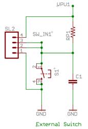
Use 0603 surface mount parts in the sparkfun library for the resistor and capacitor. Use the momentary switch (TAC_SWITCH_SND device) in that library for the switch. This would provide the push-button option link on the telos. However, we will typically leave off that switch and connect some external trip sensor. So, bring the four useful points in the circuit out to header pins so we can build lots of things with it. Use the M04PTH for the header pins.
· Why did we provide two pins for the SW_IN1?
Rough PCB
Before we go too much further, let’s bring in some of the mechanical constraints. The box we plan to use is the following.
http://www.hammondmfg.com/pdf/1551RFL.pdf
It turns out that prototyping PCB with cutouts is expensive, so we’ll stick to a rectangular board for now.
Determine the dimensions of the board and the placement of the mounting holes. Be sure to leave yourself a little safety margin. Better to make it a tiny bit loose than for it not to fit.
Start a board for your schematic, dimension it properly and put in the mounting holes, as described in the sparkfun tutorial. (You will need to do a little research to figure out how big the holes should be.)
In a real design, you would typically work out the entire requirements and functional capabilities in advance. Then you would do floorplanning to get a good idea of where the major pieces go. Here we are doing it piece by piece, so you may find your self ripping things up and moving them around. That is good practice in learning the tool, even though good design methods try to avoid that kind of stuff. Feel free to look ahead to see what all you are going to try to put on the board. An nice element of Eagle is that it allows you to move between the physical board layout and the logical schematic quite easily.
LEDs
Now let’s add some LEDs and some pins to control them. Use the LED0603 in the Sparkfun library. Notice, you turn on the LED by pulling down the pin. You might end up with something like this.
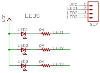
Notice, here we’ve used names to connect to the header, rather than wires. Sometimes that is easier to read. Here is doesn’t matter much.
·
Breadboard
your external LED in the lab. Make sure
it works and does not burn out the LED before connecting it to your mote.
·
Connect
it to your mote and modify your previous application to toggle this external
actuator.
External Sensor
Device
Our switch was an extremely simple binary sensor. More generally, we might have an external device with a binary output that connects to an MCU input pin. For such a device, actuation and sensing come together in the form of power management. An MCU output pin may provide power to the external device to turn it on. In this case, the controller can determine when to sense of can duty-cycle the sensor to reduce its consumption. This basic arrangement looks something like this.
Here’s an example motion sensor: http://www.parallax.com/Portals/0/Downloads/docs/prod/audiovis/PIRSensor-V1.2.pdf
Notice that in this case the power consumption is small enough that it can be provided directly from the microcontroller and it will operate at 3.3-5 volts. It actually runs fine at 3v, but it is a bit out of spec. What do we do if the external device requires more power or a different voltage level than the MCU? We need to introduce a “switch” to control that external power, i.e., a FET. It might look something like this.
Notice, the header should have 6 pins. This is a good opportunity to learn trick that will reduce how many times you spin a board and allow you to use the same PCB for a variety of things. Add a pullup resistor and a pulldown resistor to the control line. Leaving these unpopulated make the circuit just like we’ve have here. However, you can populate the resistors to get other behaviors.
· Why do we use a pFET here?
·
Add
support circuitry and a connector header to your design to support such an
external device.
·
Build a
little circuit in the lab with a pair of fixed resistors in place of the
device. Use a pFET on the high side that
is controlled by your mote (in place of controlling the LED). Using a multimeter or a scope, measure the
current though the resistors when the mote attempts to turn the device ON. When it attempts to turn it off?
·
Try this
again using an nFET.
·
When
would you put a pull-up or pull-down on the ctrl line.
·
What
voltage would you get if you sampled the point between the two resistors?
·
Modify
your breadboard LED circuit to use and external voltage source modulated by the
mote.
Let’s throw in one more because between the two we will be able to control all sorts of external devices.
·
Add
similar support circuitry and a connector header to your design but with an
nFET.
Section 2: Resistive Sensor
An important class of range-values is resistive sensors, which includes thermistors, proto-resistors, strain gauges, flex strips, and some thermocouples. Electrically, these devices are passive circuit elements with a variable resistance that changes in response to physical conditions. For example, Figure 5 shows how the resistance of a particular thermistor (Panasonic ERTJ 4500K) decreases with increasing temperature. At 0 °C, it has a resistance of 18 MΩ, at 25 °C it obtains its rated value of 4500 KΩ, whereas at 100 °C it has 220 KΩ. The datasheets for the particular sensor give the conversion functions in detail. To obtain the reading in physical units, we must observe the resistance and then compute the corresponding temperature, or whatever physical phenomenon is being sensed.
Figure 5 Characteristic Function of a Thermistor showing Resistance as a function of Temperature
While a switch has either infinite resistance (open) or zero resistance (closed) these devices take on a range of resistances in between. By placing them in a voltage divider circuit, as illustrated in Figure 6, this variation in resistance is converted into variation in voltage, which can be measured by an ADC to get a digital reading for voltages between zero (V=GND) and Dmax (V = Vref) .

Figure 6 Conversion of a Resistive Sensor to an Analog Voltage to a Digital Value
The voltage, VA, at point A in Figure 6 is equal to
VA = Vacc * Rsensor / (Rsensor
+ Rcomp),
where Vacc is the analog supply voltage, Rcomp is the resistance of the pull-up, and Rsensor is the effective resistance of the sensor.
· If the max resistance of your sensor was 10 k ohm and the minimum resistance is 100 ohm, what size pullup resistor would you use to keep the current draw through the resistor-sensor pair under the maximum allowable for an MSP430 output in?
· What will the range of current be?
· If Vacc is supplied by an MSP430 output pin and the pullup is 1 k ohm, what is the voltage across the resistor when it is at its min value? Max value? At 500 ohm? What is the current at these points?
Next week we will sample this analog input, VA, by the ADC in the microcontroller and compared to a reference voltage, Vref, to produce a digital value D between zero and Dmax such that
D = min(Dmax , Dmax
* VA / Vref ).
A 12-bit ADC is provided by the TI MSP microcontroller, so Dmax = 4095 (or 0xFFF). The reference voltage, Vref, can be set to 1.5 V, 2.5 V, or Vcc.
In many situations a constant, regulated voltage is most useful as a reference. However, for simple resistive sensors it is convenient to have the reference voltage be the same as the supply voltage to the sensor, Vref = Vacc = Vvcc, even when this is an unregulated battery voltage. This configuration is called a ratiometric sensor; all we need to determine the physical condition being sensed is the ratio of the resistances. For example, when Rsensor = Rcomp, we will get a reading of D = Dmax / 2, independent of the supply voltage. Using the lookup function from the sensor datasheet, we can convert this to physical units.
In general, for a ratiometric sensor we will get a reading of
D = Dmax * Rsensor / (Rsensor + Rcomp).
Solving for Rsensor we get
Rsensor = Rcomp * ρ / (1- ρ), where ρ = D/ Dmax.
In practice, with a ratiometric sensor, you cannot use the full range of the ADC, because the output voltage will be significantly less than the reference voltage. If a small Rcomp were used so that the output voltage would be close to the reference when the sensor resistance is large, then at the other range of the scale both resistances would be small and too much current would be drawn through the voltage divider. If Rcomp is chosen to be roughly equal to the effective sensor resistance at the high end its useful operating regime, half of the ADC range is used. (The most significant bit will be zero.) A smaller Rcomp can be used, increasing the range of readings, as long as the current does not exceed the microcontroller tolerances and power consumption fits within the application power budget.
Alternatively, if a fixed voltage reference is used for the ADC, we can determine VA from the observed input D as
VA = Vref * D / Dmax,
as long as VA < Vref. Vref will typically be smaller than the supply Vacc, so in this case, the value of Rcomp should chosen be so that at the end of the desired sensing range with the largest resistance, VA ≤ Vref.
The effective resistance of the sensor is calculated as
Rsensor = Rcomp * α / (1 – α), where α = VA / Vacc.
Current Sensor
A current sensor translates the sensed input into different values of current. A very common current sensor is the 4-20 mA current sensor. Thus, rather than sampling the voltage level, you need to sample the amount of current flowing through the sensor.
· How would you convert the output of a 4-20 mA sensor to a voltage level between 0 and 3 volts?
OK, let’s put some chips on your board. How about one to do current sensing? The basic idea is simple. We put the current through a “precision resistor” with a known resistance and measure the voltage drop. The problem is that we don’t want to put much resistance there and we don’t want to couple our ground to that point in the external circuit. Zetex makes a handy device for this. Use the ZXCT1010_SOT23 in the Zetex library.
· Find the data sheet on line to see how to hook it up and how it works. Provide a header to get at the measurement.
Accelerometer
Now let’s get even fancier. Let’s put a dual axis accelerometer on the board. The ADXL202E from analog devices is a nice part and its not too hard to solder. The part should be in the Analog Devices library, but you may need to find it on line.
· Track down the datasheet. You will need a couple of filter capacitors for this, a pulldown on T2, and a little signal conditioning on the VDD line.
Wow! All that. Give it you best shot.
Take Home Project
Your group will complete its preliminary schematic and layout for next week. We will sit down with your group and go over the design in detail. Since next Monday is a holiday, we’ll discuss in class how we’ll schedule that.
We will take the final design and send them out for fab. You’ll get them back in about a week and get a chance to populate them and bring them up.
Good luck and have fun. Don’t forget to put your name on it and a date code.