Lab 6: Pipelining, CPU, Mid-Semester Survey
Deadline: Friday, October 22, 04:00:00 PM PT
Goals
- Learn how to analyze timing for circuits.
- Better understand the motivation behind pipelining and the 5 stages in a classic RISC-V CPU.
- Design a pipelined circuit.
Setup
In your labs directory, pull the files for this lab with:
Like Lab 5, all the work in this lab will be done using the digital logic simulation program Logisim Evolution.
Some important warnings before you begin:
- Logisim is a GUI program, so it can't easily be used in a headless environment (WSL, SSH, etc.). We recommend running it in a local environment with a GUI, Java 9+, and Python 3.6+. If your local system is macOS or Linux you're probably all set. If you're on Windows, use
Git Bash, which runs on Windows with GUI support. - Please use the version of Logisim that we distribute, since it is different from other versions on the internet (bugfixes and course-specific stuff)
- Don't move the staff-provided input/output pins; your circuit can't be tested properly if the pins move. If your circuit doesn't pass the tests and you think it is correct, check that your circuit fits in the corresponding harness in
tests/ex#_test.circ - Logisim doesn't auto-save your work. Remember to save (and commit) frequently as you work!
Exercise 1 - Inefficiencies Everywhere
For this exercise, we can assume that registers initially carry the value zero. We will be using the lab file ex1.circ, which should have a subcircuit called non_pipelined which looks something like this:
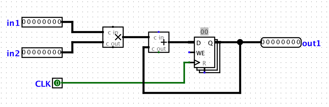
This circuit simply takes two inputs, multiplies them together, and then adds the result to the current state value. For this circuit, let the propagation delay of an adder block be 45ns and the propagation delay of a multiplication block be 60ns. The register has a CLK-to-Q delay of 10ns, setup time of 10ns, and hold time of 5ns. Assume that both inputs receive their data from registers (so the inputs arrive CLK-to-Q after the rising edge).
Action Item
- Calculate the length of the critical path of this circuit in ns. Put this number in ex1.txt without units.
Exercise 2 - Pipe that Line
We want to improve the performance of this circuit and let it operate at a higher clock rate. In order to accomplish this, we want to have two stages in our pipeline: a multiplication stage and an addition stage, in that order.
To pipeline the circuit, we need a register to hold the intermediate value of the computation between pipeline stages. This is a general theme with pipelining.
In order to check that your pipelining still produces correct outputs, we will consider the outputs from the circuit "correct" if and only if it corresponds to the sequence of outputs the non-pipelined version would emit, bar some leading zeroes.
In your ex1.circ file, the main circuit is set up to produce the output sequence [3, 5, 1, 2, 4, -1, 0, 0, …] from the non-pipelined version of the circuit. Thus, the correct pipelined circuit should emit the sequence [0, 3, 5, 1, 2, 4, -1, 0, 0, …] for the same sequence of inputs. You can check this by simulating the circuit (using the "Simulate" menu dropdown) and either ticking the clock manually or enabling continuous ticks.
Action Item
- Complete the sub-circuit
pipelined. You will need to add a register to divide the multiplication and addition stages up. - We discussed that if an instruction depends on the output of a previous instruction, it's difficult to pipeline them and we often need to insert a pipeline "bubble" (or several) to ensure that the output of the first instruction is ready to be an input to the second. As a reminder, a bubble purposely delays an instruction in the pipeline.
Why are such "bubbles" unnecessary for this particular circuit?
For this exercise, one instruction consists of BOTH an addition and a multiplication. The addition and multiplication are not two separate instructions.
Instead, they are two separate stages in the pipeline, similar to how EX and MEM are two separate stages in a pipeline that operate on the same instruction with EX operating on the instruction first and MEM operating on the instruction second.
We do not have any bubbles in this particular circuit because none of the individual instructions depend on each other.
- Calculate the critical path of this pipelined circuit in ns. Put this number on the first line of ex2.txt without units.
- Calculate the maximum clock rate for this pipelined circuit in MHz. Put this number on the second line of ex2.txt without units.
Testing
Open a local terminal session and go to the lab06 folder. We've provided tests for Exercise 2, which you can run with python3 test.py. Your Exercise 2 circuit is run in a test harness circuit (tests/ex2-test.circ), and its output is compared against the reference output for that test (tests/reference-output/ex2-test.out). In the output file, each column corresponds to an input/output pin on the main circuit, and each row shows a set of inputs and the corresponding outputs the circuit produced. If your circuit output (tests/student-output/ex2-test.out) is different, you can check it against the reference output file; the diff command may help.
Exercise 3 - Lab 6 Feedback
We are working to improve the labs for next semester, so please fill out this survey to tell us about your experience with Lab 6. The survey will be collecting your email to verify that you have submitted it, but your responses will be anonymized before the data is analyzed. Thank you!
Exercise 4 - Mid Semester Survey
Congratulations on making it halfway through 61C! We request that you provide feedback on how the course is being run so we can better meet your learning needs for the remainder of the course. This feedback survey is only collecting emails to verify that you have completed it. When the results are analyzed, the data will be anonymized. The content of your responses will not affect your grade.
Submission
Save, commit, and push your work, then submit to the Lab 6 assignment on Gradescope.