Lab 7
Deadline: EOD Tuesday, March 19th
Objectives:
- TSW understand more about the 5 stages in our CPU and be able to understand certain design choices behind the design of the CPU
- TSWBAT analyze timing for circuits and design circuits that take advantage of the pipelining principle
Setup
Pull the Lab 7 files from the lab starter repository with
git pull staff master
All the work in this lab will be done from the digital logic simulation program Logisim Evolution, which is included in the lab starter files.
IMPORTANT: Please use the .jar file we’ve given you, not the version of Logisim that is downloaded on the lab computers! And a note: Logisim does not save your work as you go along, and it does not automatically create a new .circ file when you open it! Save when you start, and save frequently as you work.
You can open Logism via:
java -jar logisim-evolution.jar
IMPORTANT: Logism is a Java program that requires a GUI, so doing the lab over terminal won’t work (without window forwarding, detailed below). If you wish to work on the lab locally, ensure you have Java installed on your local machine, and pull the latest lab starter files to your local machine. Then, you should be open the program as above. If you wish to run the program over the terminal, you will need to add the -X flag to your SSH command to enable window forwarding (for example, ssh -X cs61c-xxx@...). On Windows machines, you may need to additionally install Xming.
Exercise 1 - Inefficiencies Everywhere
For this exercise, we can assume that registers initially carry the value zero. We will be using the lab file exercise1.circ, which should have a subcircuit called non_pipelined which looks something like this:
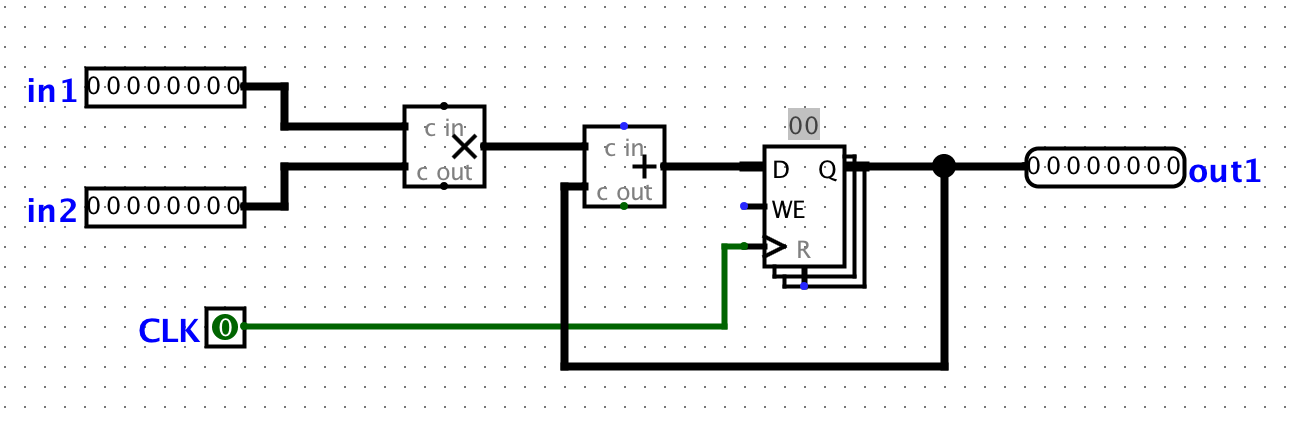
All this circuit does is take in two inputs, multiply them together, then adding it to the current state value. For this circuit, let the propagation delay of an adder block be 50ns, the propagation delay of a multiplication block be 55ns, and the CLK-to-Q delay of a register is 5ns. Assuming no setup time and hold time, calculate the maximum clock rate at which this circuit can operate. Assume that both inputs come from clocked registers that receive their data from an outside source.
Checkpoint
- At this point, make sure that you are comfortable with calculating clock rate using propagation delays and finding the critical path
- Be ready to show your calculations to achieving the maximum clock rate for the non-pipelined circuit.
Exercise 2 - Pipe that Line
We want to improve the performance of this circuit and let it operate at a higher clock rate. In order to accomplish this, we want to have two stages in our pipeline: a multiplication stage and an addition stage, in that order.
In order to check that your pipelining still produces correct inputs, we will consider the outputs from the circuit “correct” if and only if it corresponds to the sequence of outputs the non-pipelined version would emit, bar some leadings zeroes. For example, if for some sequence of inputs, the non-pipelined version emits the sequence [3, 5, 1, 2, 4, …]. Then, the correct pipelined circuit might emit the sequence [0, 3, 5, 1, 2, 4, …] for the same sequence of inputs.
In your exercise1.circ file, the main circuit is set up to produce the output sequence [3, 5, 1, 2, 4, -1, 0, 0, …] from the non-pipelined version of the circuit. The ROM blocks should be initialized to the proper inputs, but if something goes wrong, select the ROM, click on “Contents”, click “Open”, then choose Romdata.
Note that in order to pipeline the circuit, we need a register to hold the intermediate value of the computation between pipeline stages. This is a general theme with pipelines.
Tasks
- Complete the sub-circuit
pipelined. You will need to add a register to divide the multiplication and addition stages up. - Calculate the maximum clock rate for the pipelined version of the circuit that you have created
- We discussed that if a computation depends on the output of a previous computation, it’s difficult to pipeline them and we often need to insert a pipeline “bubble” (or several) to ensure that the output of the first computation is ready to be an input to the second. As a reminder a bubble is the process of purposely delaying an instruction in the pipeline. It is important to understand why such “bubble”s are unnecessary for this particular circuit.
Checkpoint
- At this point, make sure you are comfortable figuring out the clock rate for a pipelined circuit
- Be ready to show your calculations for achieving the maximum pipelined clock rate and know why this circuit does not require any “bubble”s.
Exercise 3 - Mid Semester Survey
As part of the semester, we ask that you provide feedback for how the course is going. While we keep answers anonymous, we require that all students fill out the survey to receive credit for this lab. You can find the link here. All you need to show is the “You’ve already responded” page to receive credit for this portion
Checkpoint
- At this point, you should have already filled out the form and have the “You’ve already responded” page open and ready.
Checkoff
Exercise 1:
- Show your calculations for the maximum clock rate for the non-pipelined circuit
Exercise 2:
- Show your shiny new pipelined circuit
- Show your calculations for the maximum clock rate for the pipelined circuit
- Explain why we don’t need any “bubble”s for our pipelined circuit
Exercise 3:
- Show you have responded to the mid semester survey