Lab 6
Deadline: Friday, March 12th
Objectives:
- TSWBAT analyze timing for circuits and design circuits.
- TSW better understand the motivation behind pipelining and the 5 stages in our CPU.
Setup
Pull the Lab 6 files from the lab starter repository with
git pull starter master
As lab5, all the work in this lab will be done from the digital logic simulation program Logisim Evolution.
Some warnings before you start of importance:
- Logisim is a GUI program, so it can’t easily be used in a headless environment (WSL, Hive SSH, other SSH server, etc.). We recommend running it in a local environment with a GUI (Windows users, remember that WSL is headless, but Git Bash run outside of WSL)
- Please use the version of Logisim that we distribute, since it is different from other versions on the internet (bugfixes and course-specific stuff)
- Don’t move the staff-provided input/output pins; your circuit can’t be tested properly if the pins move. If your circuit doesn’t pass the tests and you think it is correct, check that your circuit fits in the corresponding harness in
tests/ex#_test.circ. - Logisim doesn’t auto-save your work. Remember to save (and commit) frequently as you work!
Exercise 1 - Inefficiencies Everywhere
For this exercise, we can assume that registers initially carry the value zero. We will be using the lab file ex1.circ, which should have a subcircuit called non_pipelined which looks something like this:
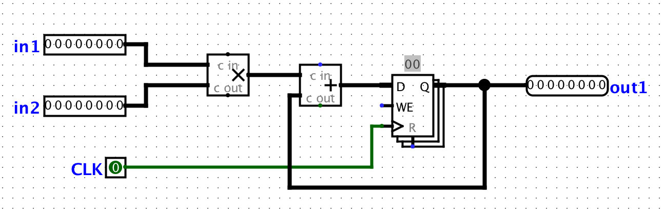
All this circuit does is take in two inputs, multiply them together, and then add the result to the current state value. For this circuit, let the propagation delay of an adder block be 45ns and the propagation delay of a multiplication block be 60ns. The register has a CLK-to-Q delay of 10ns, setup time of 10ns, and hold time of 5ns. Assume that both inputs come from clocked registers that receive their data from an outside source.
Action Item
- Calculate the critical path of this circuit can operate in ns. Put this number in ex1.txt without units.
Exercise 2 - Pipe that Line
We want to improve the performance of this circuit and let it operate at a higher clock rate. In order to accomplish this, we want to have two stages in our pipeline: a multiplication stage and an addition stage, in that order.
In order to check that your pipelining still produces correct outputs, we will consider the outputs from the circuit “correct” if and only if it corresponds to the sequence of outputs the non-pipelined version would emit, bar some leadings zeroes. For example, if for some sequence of inputs, the non-pipelined version emits the sequence [3, 5, 1, 2, 4, …]. Then, the correct pipelined circuit might emit the sequence [0, 3, 5, 1, 2, 4, …] for the same sequence of inputs. You can check this by simulating the circuit (using the “Simulate” menu dropdown) and either ticking the clock manually or enabling continuous ticks.
In your exercise1.circ file, the main circuit is set up to produce the output sequence [3, 5, 1, 2, 4, -1, 0, 0, …] from the non-pipelined version of the circuit. The ROM blocks should be initialized to the proper inputs, but if something goes wrong, select the ROM, click on “Contents”, click “Open”, then choose Romdata.
Note that in order to pipeline the circuit, we need a register to hold the intermediate value of the computation between pipeline stages. This is a general theme with pipelines.
Action Item
- Complete the sub-circuit pipelined. You will need to add a register to divide the multiplication and addition stages up.
- Calculate the maximum clock rate for the pipelined version of the circuit that you have created
- We discussed that if a computation depends on the output of a previous computation, it’s difficult to pipeline them and we often need to insert a pipeline “bubble” (or several) to ensure that the output of the first computation is ready to be an input to the second. As a reminder a bubble is the process of purposely delaying an instruction in the pipeline. It is important to understand why such “bubbles” are unnecessary for this particular circuit.
- Calculate the critical path of this circuit can operate in ns. Put this number in ex2.txt without units.
Testing
Open a terminal session and go to the lab06 folder. We’ve provided tests for each exercise, which you can run with python3 test.py. Your exercise 2 circuit is run in a test harness circuit (tests/ex2-test.circ), and its output is compared against the reference output for that test (tests/reference-output/ex2-test.out). In the output file, each column corresponds to an input/output pin on the main circuit, and each row shows a set of inputs and the corresponding outputs the circuit produced. If your circuit output (tests/student-output/ex2-test.out) is different, you can check it against the reference output file; the diff command may help.
Exercise 3 - Mid Semester Survey
As part of the semester, we ask that you provide feedback for how the course is going. Even though we will be collecting your email to ensure you have completed the survey, we will only look at your feedback and will not link your feedback to your email. The head TAs ensure this by hiding the initial response spreadsheet and copying it over without the email column once this lab is due. You can find the survey at: https://forms.gle/mV5NzGDxrhaXaNYd8.
Submission
Save, commit, and push your work, then submit to the Lab06 assignment on Gradescope.