Lab 3, Radio Communication Via a Computer Interface, Part III AFSK, AX.25 and APRS
In this part of the lab we are going to experiment with Digital modulation and communication. Network Communication systems have layered architechture. The bottom layer is the physical which implements the modulation. Here we will use AFSK, which is a form of BFSK in the audio range (hence the 'A'). We will write a modulator/demodulator for AFSK. In addition, we will leverage AX.25, which is an amateur-radio data-link layer protocol. AX.25 is a packet based protocol that will help us transmit data using packets. It implements basic synchronization, addressing, data encapsulation and some error detection. In the ham world, an implementation of AFSK and AX.25 together is also called a TNC ( Terminal Node Controller ). In the past TNC's were separate boxes that hams used to attach to their radios to communicate with packet-based-communication. Today, it is easy to implement TNC's in software using the computer's soundcard.... as you will see here!
For the following tasks you will need the functions:
sg_plot
myspectrogram_hann_ovlp
play_audio
record_audio
audioDevNumbers
text2Morse (to Identify yourself before transmission)
AFSK1200, or Bell 202 modem
AFSK1200 encodes digital binary data at a data-rate of 1200b/s. It uses the frequencies 1200Hz and 2200Hz ( center frequency of \(1700\)Hz \(\pm 500\) Hz) to encode the '0's and '1's (also known as space and mark) bits. Even though it has a relatively low bit-rate it is still the dominant standard for amature packet radio over VHF. It is a common physical layer for the AX.25 packet protocol and hence a physical layer for the Automatic Packet Reporting System (APRS), which we will describe later.
The exact frequency spectrum of a general FSK signal is difficult to obtain. But, when the mark and space frequency difference \(\Delta f\) is much larger than the bit-rate, \(B\), then the bandwidth of FSK is approximately \(2\Delta f + B\). This is not exactly the case for AFSK1200 where the spacing between the frequencies is 1000Hz and the bit-rate is 1200 baud.
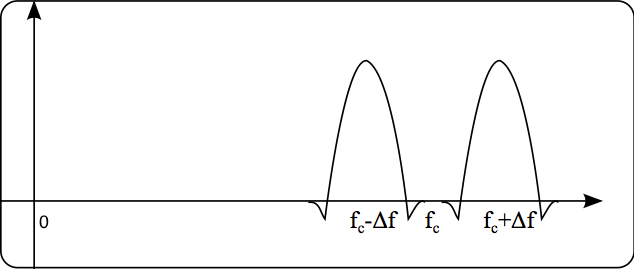 Figure 2: Approximate spectrum of AFSK
Note, that for the (poor) choice of 1200/2200Hz for frequencies, a synchronous phase (starting each bit with the same phase) is not going to be continuous. For the Bandwidth to be narrow, it is important that the phase in the modulated signal is continuous. For this reason, AFSK1200 has to be generated in the following way: \[ s(t) = cos\left(2\pi f_c t + 2\pi \Delta f \int_{\infty}^t m(\tau)d\tau \right),\] where \(m(t)\) has the value =1 for a duration of a mark bit, and a value =-1 for a duration of a space bit. Such \(m(t)\) signal is called an Non-Return-to-Zero (NRZ) signal in the digital communication jargon. Here's a link to some notes provided by Fred Nicolls from the university of Cape Town
The integration guarentees that the phase in continuous. In addition, the instantaneous frequency of \(s(t)\) is the derivative of its phase, which is \(2\pi f_c + 2\pi \Delta f m(t)\), which is exactly what we need.
Write a function sig = afsk1200(bits) the function will take a bitarray of bits and will output an AFSK1200 modulated signal of them, sampled at 44100Hz. Note that Mark frequency is 1200Hz and Space Frequency is 2200Hz. If your USB device prefers 48000Hz, then use 48KHz for the sampling rate.
Note, that 44100 does not divide by 1200. Make sure that you produce signals that have the right rate over time. (44100 does not divide by 1200, but 44100*4 does).
- Generate a sequence of 64 randomly generated bits with equal probability. Generate the AFSK1200 signal and compute its spectrum.
- Does the spectrum looks like the one in Figure 2?
AFSK1200 demodulation
AFSK is a form of digital frequency modulation. As such it can be demodulated like FM. Because AFSK alternates between two frequencies, we can place two bandpass filters around the frequency of the Mark and Space and use envelope detection to determine which frequency is active in a bit period. This is a non-coherent AFSK demodulation, because the receiver phase does not need to be synced to the transmitter phase in order to demodulate the signal. The implementation we will use here is loosly based on on the one by Sivan Tolede (4X6IZ), a CS faculty in Tel-Aviv university who has written a nice article on a high-performance AX.25 modem. You can find it Here.
Non-Coherent Demodulation of AFSK
Here's a diagram of a non-coherent AFSK1200 demodulator that returns an NRZ signal:
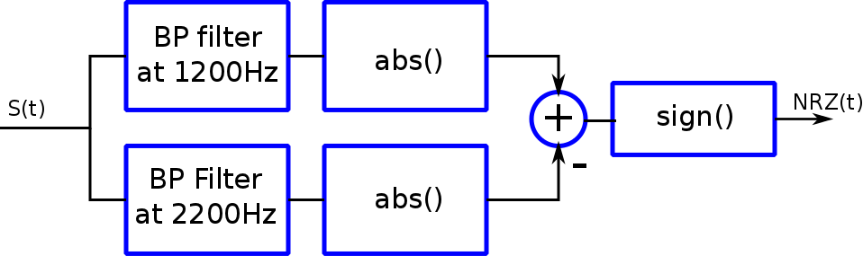 Figure 3: AFSK1200 non-coherent demodulator
- Using signal.firwin design a TBW=2 LP filter with a (two-sided) bandwidth of approximately 1200Hz for a sampling rate of 44100Hz.
- From the LP filter gernerate two bandpass filters by complex modulating the LP filter to 1200Hz and 2200Hz respectively.
- Filter the random stream of bits you generated previously using the two filters.
- The absolute value of the result represents the envelope of the filtered signal. The difference between the envelopes should represent the NRZ signal. Display the difference between the envelope of the resulting two signals. Can you see the bits?
- Extract the digital NRZ signal by computing the signum (
sign) function of the difference.
- The bit value is the value of the NRZ function in the middle of the bit period. Decode the bits and compare to the original ones. Don't forget to compensate for the delay of the filter. Overlay a stem plot on top of the NRZ signal at the indexes in which you sampled the bit values. Make sure as a sanity check that you actually sampled at the middle of the interval.
FM demodulation of AFSK
We can also demodulate AFSK using FM demodulation. Recall that the bandwidth of AFSK is approximately \(2\Delta f + B\) where \(B\) is the bitrate (1200Hz for AFSK1200). The afsk signal is \(s(t) = cos\left(2\pi f_c t + 2\pi \Delta f \int_{\infty}^t m(\tau)d\tau \right)\). If we filter the signal by passing only the positive frequencies we will get \(s(t) = \frac{1}{2}e^{2\pi j f_c t + 2\pi j \Delta f \int_{\infty}^t m(\tau)d\tau}\). This is the analytic signal and we can FM demodulate it in a similar way as we did for the FM radio Lab by taking the derivative of the phase. After appropriate scaling and offset we can extract the NRZ signal.
- Design a low-pass filter with the appropriate BW.
- Complex modulate the LP filter to create a BP filter centered around 1700Hz.
- Use the BP filter to get the analytic signal.
- FM demodulate the signal, scale and offset the signal appropriately to get the "analog" NRZ signal of approximately \(\pm 1\)
- Optional: Low-pass filter the signal with a cutoff frequency of 1200Hz to reduce demodulation noise.
- Remember that '1' is the 1200Hz frequency and '0' is 2200.
- rectify the resulting NRZ by taking the signum function of it.
- make a plot similar to the non-coherent asfk demodulation
- Write a function nc_afskDemod(sig, TBW=TBW, N=Nfilter) that implements the above non-coherent demodulation and returns the "analog" NRZ (i.e. without rectifying it). You can assume that the sampling rate is 44100Hz (or 48000 if you used that rate before)
- Write another function fm_afskDemod(sig, TBW=TBW, N=Nfilter) that implements the above fm demodulation and returns the "analog" NRZ (i.e. without rectifying it). You can assume that the sampling rate is 44100Hz (or 48000 if you used that rate before)
Bit Error Rate (BER)
One of the ways to evaluate the properties of a digital modulation scheme is to compute the bit-error-rate (BER) curves with as a function of signal-to-noise ratio (SNR). The BER is the number of bit errors (received bits that have been altered due to decoding error) divided by the total number of transmitted bits.
Let's calculate the BER for AFSK with both the non-coherent and FM demodulations:
- Generate a 10000 long random bitstream
- AFSK1200 modulate the bitstream
- Add random gaussiam noise with a standard deviation of 1 to the afsk signal.
- demodulate using both methods and compute the BER
- plot the first 300 samples of the ourput of the BP filters of the non-coherent demodulation and the analog NRZ of the fm demodulation to see how erros look like
Your Bit error rate will depend also on the quality of the reconstruction. You can try to repeat the experiment for different choices of filters if you like.
Computing BER curves
BER curves are usually displayed in log log of the BER vs SNR. SNR is measured by energy per bit over noise power spectral density. Since we are just interested in the trend, we will plot the BER vs 1/noise standard deviation
- Repeat the experiment for \(\sigma=[0.1:8.0:0.1]\)
- Use the function loglog to plot the BER as a function of 1/\(\sigma\)
- Which scheme is more resilient to noise (The result will depend on your implementation)
AX.25 (from: http://n1vg.net/packet/ and http://www.tapr.org/pub_ax25.html)
Before we go to demodulate AFSK1200 we will construct data in the form of AX.25 packets. The structure of the AX.25 packet, and in particular the flag that starts and ends a frame will help us sync to the beginning of the packet for accurate demodulation. The AX.25 protocol uses several measures for standartization and to improve detection and demodulation of packets. We will go over them now:
NRZI (non-return to zero inverted)
AX.25 does not encode NRZ '1's and '0's in the usual mark and space frequencies. Instead it uses a scheme called NRZI, or non-return to zero inverted. NRZI encodes a '0' bit as a change from mark to space, or space to mark. A '1' is encoded as no change. To encode an AX.25 packet we need to convert our bit sequence to an NRZI one. For example, an original bit stream of 11011000 should be first converted to 11000101 (initial state is 1).
Bit Stuffing
Because a '1' is represented by no change, sending a long string of '1's would result in a constant signal. This may result in a receiver drifting out of sync with the transmitter. In order to circumvent this, the encoder performs bit stuffing before by placing a bit '0' after every fifth '1' in the the stream. The decoder does bit unstuffing and removes the extra '0's. Bit stuffing is performed before converting to NRZI.
Bit Order
Bytes are sent least-significant-bit first
Flag
A Flag field starts and ends each packet. It is a unique sequence and is used to detect the beginning and the end of packets. The flag consists of the bit sequence: 0x7E or: 01111110. The flag is an exception in which no bit stuffing is performed. Therefore it is the only place in the packet in which 6 consequitive '1's appear. In NRZI it will translate to a time interval of 7 bits between zero-corssing of the non-coerent detector output. This means that we can use the flag sequence to uniquly detect a packet.
Frame Structure
The Ax.25 protocol defines several type of frames. We will use the Unnumbered Information (UI) frame as defined in the protocol. UI frame is used for connectionless mode, where AX.25 frmaes are transmitted without expecting any response, and reception is not quaranteed. The UI frame that is used in the Automatic Positioning and Reporting System (APRS) protocol and has 9 fields of data:
Of importance are the Source address, which are your call sign, the Information Field which is the packet payload, the FCS which is a error checksum.
FCS Field
The FCS field is always the last two bytes in the packet. They are a checksum that can be used to determine the integrity of the packet.
APRS is a ham packet-based system for real-time tactical digital communication for local area. APRS uses the AX.25 protocol in its core. Using APRS you can report position, status, and send messages that other hams or stations with APRS capability will able to decode, interpret and display the information. APRS also provides means of packet repeating (Digipeters) alongside with internet terminal nodes. Some radio manufacturers saw the potential and included APRS in some of their products as well. Go to this website: https://aprs.fi to see the APRS activity in the surrounding area that is aggregated by from the internet nodes. You will see fixed stations, weather stations as well as mobile operators in your area. We will use the website to confirm that our transmitted packets were received.
Frequencies:
The national APRS frequency is 144.39MHz (ch-117 on your radio). There is much activity and infrastracture transmitting and listenning to that frequency. The international space station also has an APRS digipeter on board operating at 145.825MHZ (ch-50 on your radio). You can also use AX.25 on any of the digital or experimental channels in the bandplan -- though you will have to coordinate if you want anybody to hear you!
APRS Destination, source, digipeter address, control, ID and FCS packet fields
For APRS packets, the Destination address field is not used for routing. Instead it represents the version of the APRS software you are using. In order to be decoded by receivers in the APRS network it must start with the letters AP. We will use APDSP just for fun. The source address is your call sign. The digipeter addresses require some explenation but the fields 'WIDE1-1,WIDE2-1' will result in the packet being digipeted a maximum of 2 hops. In dense population areas like the bay area 'WIDE1-1' is often enough to get your packet to its destination. The Control and ID fields are fixed to "03" and "0" respectively. The FCS field is the checksum field as defined by AX.25. The flag fields are the usual 01111110.
We have prepared for you code that generates valid bitstream of AX.25 packets from the appropriate fields as well as decode the fields from a bitstream. The code is a modification of code oroginally written by: Greg Albrecht W2GMD. You can download the code from: https://inst.eecs.berkeley.edu/~ee123/sp14/lab3/ax25.py.
The information field of the packet are 256 Bytes payload that contain the information you want to send. We will go over some of the information that is needed to construct valid and useful information field messeges. There are several digipeters in the bay area that have internet terminal nodes. These implement several "fun" and useful services. For example, you can send a position report that would show up on a google map. You can also send a short EMAIL by sending an APRS packet.
How a node or a client interprets your packet depends on the information field structure. There are three types of packets: Position, Status and Messages #### Messages
Just begin your packet line with a Colon and a 9 character TOASDDRESS, another colon and then text. The TOADDRESS must have 9 characters and should be filled with spaces if it is smaller.
Examples of messages:
- :ALL------:Everyone will capture this 64 byte message text.
- :KK6MRI---:This message will only show on Miki's APRS enabled Yaezu VX-8dr radio screen
- :EMAIL----:mlustig@eecs.berkeley.edu I sent you an email Miki through an OpenAPRS node!
The "-----" are blank spaces to fill the space to 9 characters.
Position
You can report your position to people on the APRS system. If your report is picked up by a node it will show up on http://www.aprs.fi. The basic format of a position packet is:
| = |
3752.50N |
/ |
12215.43W |
K |
Shows a school symbol on Cory Hall position |
| = |
3752.45N |
/ |
12215.98W |
[ |
Shows a person walking on Oxford and Hearst |
| = |
2759.16N |
/ |
08655.30E |
[ |
I'm on the top of the world! (Mt. Everest) |
The latitude format is expressed as a fixed 8-character field, in degrees and decimal minutes (to two decimal places), followed by a letter N for north and S for south. Latitude minutes are expressed as whole minutes and hundredths of a minute, separated by a decimal point. Longitude is expressed as a fixed 9-character field, in degrees and decimal minutes (to two decimal places), followed by the letter E for east or W for west. Longitude degrees are in the range 000 to 180. Longitude minutes are expressed as whole minutes and hundredths of a minute, separated by a decimal point.
In generic format:
- Latitude is expressed as: ddmm.hhN (i.e. degrees, minutes and hundredths of a minute north)
- Longitude is expressed as: dddmm.hhW (i.e. degrees, minutes and hundredths of a minute west)
For example Cory Hall is at N37° 52.5022', W122° 15.4395'. So the position is encoded as: 3752.50N/12215.43W
You can go to http://www.gpsvisualizer.com/geocode to find the coordinates of an address. Note: use the degree, minutes representation, not the decimal one.
a 1 character icon is provided after the coordinates. This will show an icon on the http://aprs.fi maps. Here are some useful ones:
- - House with a VHF vertical
- < Motorcycle
- > Car
- Y Sailboat
- b Bike
- [ Jogger, walker, runner
- X Helo
- K School
Examples:
a school symbol * =3752.50N/12215.43WKShows a school symbol on Cory Hall position. * =3752.45N/12215.98W[Shows a person walking on Oxford and Hearst * =3752.❏❏N/12215.❏❏-Shows a house symbol somewhere in Berkeley.
Status
A status packet starts with '>' character. It wil show on APRS equipped radios.
Examples:
- >I like radios
- >Monitoring 146.430MHz PL 66
- >On My way home
Your first APRS packet
In the following section we will construct a valid (bitstuffed) bitstream from the different APRS packet fields. We will convert to an NRZI representation and modulate to generate a valid AFSK1200 APRS Packet. We will transmit it over the radio and loog at http://aprs.fi to see if it was received by a node.
Bitstream from APRS fields
The following code shows you how to construct a message packet that will tell a digipeter to send you an email. Make sure you fill the correct information in the fields. The bitstream will already be bitsuffed with zeroes.
Converting a stream of bits to NRZI (zeros represent by change of 0-1 or 1-0 and ones are no change)
Recall that AX.25 packets are sent with NRZI encoding in which a '0' is a change and a '1' is no change.
- The following function
NRZI = NRZ2NRZI(bits), takes a standard bitarray stream and converts it to a bitarray stream representing '0's as change and '1's as unchanged. For example, an input of 0000111100 will result in 0101111101. This assume an initial state of '1'.
Constructing and Transmitting an APRS AX.25 Packet.
- Construct an AFSK1200 signal out of the APRS packet.
- Play the audio on your computer speaker. It will sound like an old modem (which is what it is!)
- Plot its spectrogram. You should be able to see the bits.
- It is recommended to add a stream of 160 zero-bits before the message. This will translate into alternating between Mark and Space and help any receiver to lock on the bit rate and sync to the package
- Tune your radio to the APRS national frequency: 144.39MHz or Channel 117 on your radio.
- Send the APRS packet through your radio. As always it is better to be outside in a high place. Don't forget to add a PTT signal to the Queue BEFORE the AFSK1200 packet.
- Note that the radio will not transmit in VOX mode if it is receiving at that time. You might need to try a few time if the APRS channel is busy.
- Sometimes it is useful to send the packet twice, just to make sure it goes through.
- Did you get an email? If so, try sending a position report and check in https://aprs.fi. You can also search for your callsign, and then press the raw-packets link. It will show you all the packets received from you in the last 48 hours.
Decodeing AX.25 and APRS Packets
Now that we know how to create AX.25 and APRS packets, know how to AFSK1200 modulate them, know how to demodulate AFSK1200 as well, we can move forward to receiving and decoding packets. By the end of that we will have a fully functioning communication system.
Download the file ISSpkt.wav. It contains an APRS packet I recorded on one of the ISS flybyes. Load it to your workspace using the function wavread, which we imported from scipy.io. (ISSpkt.wav)
We will now automate the packet decoding by writing some functions that implement portions of the process.
- Run the function
nc_afskDemod on the ISS to get the demodulated "analog" NRZI
- Plot the signal. It should look like a signal with \(\pm1\) switching!
- compute the signum to get the rectified digital NRZI.
Decoding Bits from the Demodulated NRZI Signal
We know how to get the NRZI signal, but the main issue that is left to resolve is to detect when a packet is received and synchronize to the beginning of it so we can correctly interpret its bits.
There are many ways to do this. Here we will use a simple decoder that is based on zero-crossings of the NRZI sequence. Recall that a '1' is encoded by no change and a '0' is encoded by change of sign. Therefore, if we see a 1 bit time-length between zero crossing we can decode that transition as a '0'. If we see 2 bit time-length between zero crossings of the NRZI we can decode this as '10'. Similarly if we see a 3 bit time-length we decode it all as '110', 4 as '1110', 5 as '11110' and 6 as '111110'. Because of the bit-stuffing, the only 7 bit time-length valid sequence is the flag sequence that marks the begining and the end of the packet. Of course we can not expect the transitions to be accurate due to noise and other corruptions. We therefore give an error margin of 1/2 a bit-length for decoding. For example, we will decode a '0' for zero-crossing interval between 1/2 a bit and 3/2 bits., a '10' for zero-crossing interval between 3/2 and 5/2 bits, etc.
We have implemented the decoding as a state machine for you. We first look for a flag sequence. When it is found we start collecting the bits of the packet. If at any time we get an invalid interval length we discard the data and start looking again for a flag. If the second flag is detected, a packet is announced. We then check if the checksum is valid. If it is, the packet is recorded and returned.
Here's the code to decode the packet:
AX25 Stream Processing
The idea in the next task is to implement a stream processing in which a continuous stream of data is coming and we would like to process and decode packet in real time. The idea is simple, we get a buffer of samples and decode packet within it. There are two issues: 1. Our filtering needs to mitigate with boundaries between packets. We will solve it by overlapp and save type of an approach. 2. A packet may start towards the end of the buffer and continue to the next. The length of a packet is much bigger than the filter. Therefore, if that situation happens, the function detectFrames will return the position of the lastFlag within the current buffer. If there is no such flag, it will return -1.
For simplicity we will work on 1 second length buffers.
- Download the file ISSpkt_full.wav. It contains the entire ISS flyby recording.
The following code will put chunks of 1024 samples into a queue. It also adds the string "END" to the end of the queue. You can use it to break the function so it does not hang. This simulates what the audio receive function would do:
Task:
- Write code that would read samples from the queue and process them correctly such that the data is demodulated and packets are decoded. The code should print the decoded packets information. With my code I was able to decode 20 packets. It is recommended that you first collect several 1024 chunks into a bigger buffer to be demodulated and processed -- somewhere between 43-86 will correspond to a 1-2 second long buffer.
- In order that your function exits well and does not get stuck on an empty Queue, check after getting a stream from the Queue if it is the string "END". If it is, Exit.
- Once you decoded the packets, you can search on QRZ.com and get information on the people who sent them.
Final Task: Full functioning APRS packet tranciever
- Create a standalone python application (not through notebook).
- The application should receive samples from the radio into a Queue
- The application should play the receives samples on the computer speaker
- The application should demodulate and decode packets in real-time and display on the screen
- the application will also accept a keyboard input (using the function
info = raw_input("MSG:")). When a message is typed the application will construct an APRS packet (add also 160 zeros to the beginning), modulate it (add PTT signal of course) and transmit it through the radio
The packet parameters should be set to:
- Digi =b'WIDE1-1,WIDE2-1'
- dest = "APDSP"
Don't forget to update your call sign!
You can either operate on the APRS frequency, decode packets and send in real time, try to communicate through the ISS, or use one of the digital channels and text your friends!
This is the last Lab. I hope you enjoyed them all.
Miki