EE40 Summer '04, Lab5
Introduction
You will design a bandpass filter. There are many way of designing a bandpass filter, some of them are really smart implementation but they require knowledge that you don't have yet. Using few basic things that were discussed in the lectures, you will be able to implement a bandpass filter even if your implementation is not the most efficient.
Figure 1 shows the output voltage amplitude vs. frequency for both high pass (HP) and low pass (LP) filters.
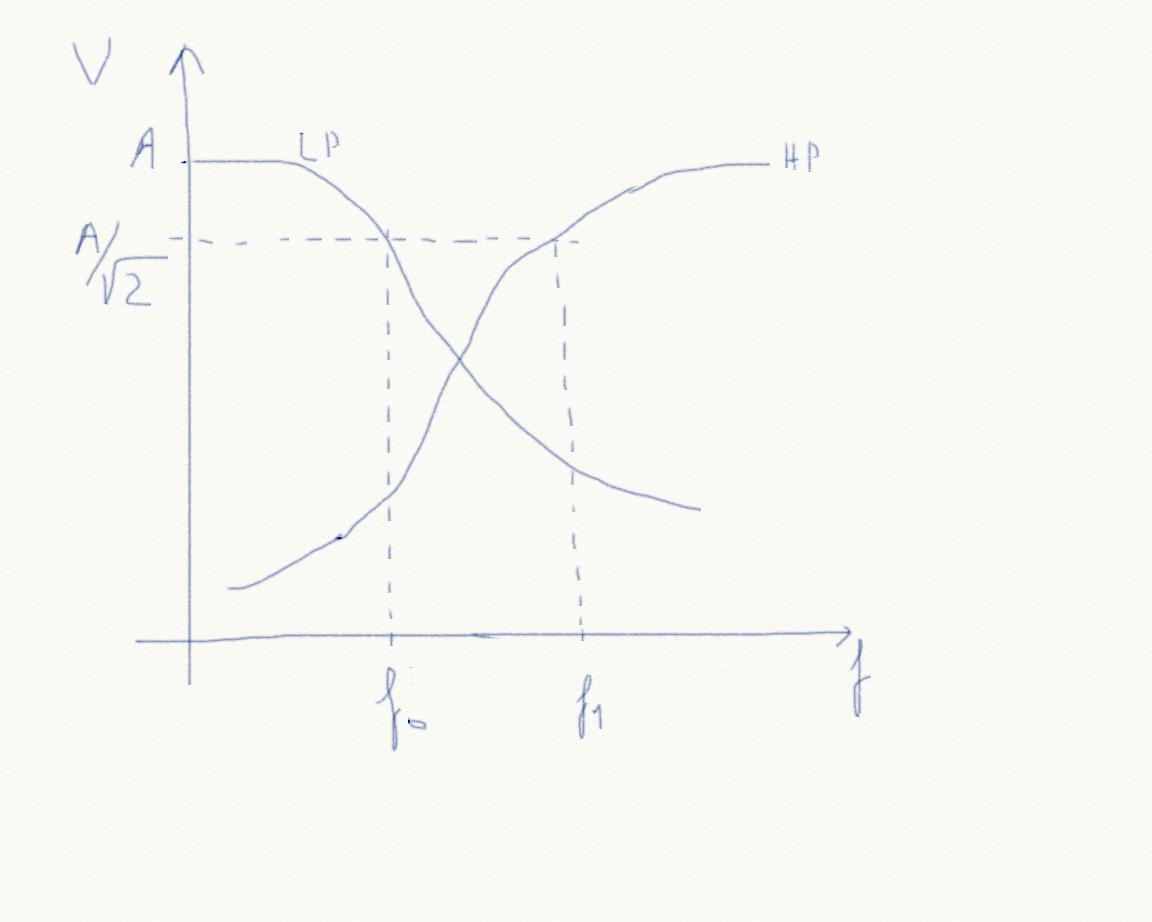 Figure 1
 In figure 1, f0 is the cutoff frequency of the low pass filter and f1 is the cutoff frequency of the high pass filter.
I'm assuming that you know how to build a low pass filter and a high pass filter (if you don't remember how to set cutoff frequencies or how the filters look like please review the lecture notes).
Figure 2 gives an hint on how to build a bandpass filter.
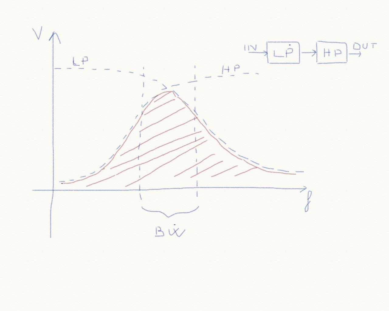 Figure 2
 If we connect the output of a low pass filter to the input of an high pass filter, then only the intersection of the two will be allowed to reach the output (the zone marked in red in figure 2). Of course if the cutoff frequency of the high pass filter is much higher than the cutoff frequency of the low pass filter then the intersection will be empty and nothing will ever reach the output of the cascade.
We define the filter bandwidth in the following way:
BW = (f0 -f1) if f0 > f1
BW = 0 if f0 < f1
Our filter then could be implemented as in figure 3.
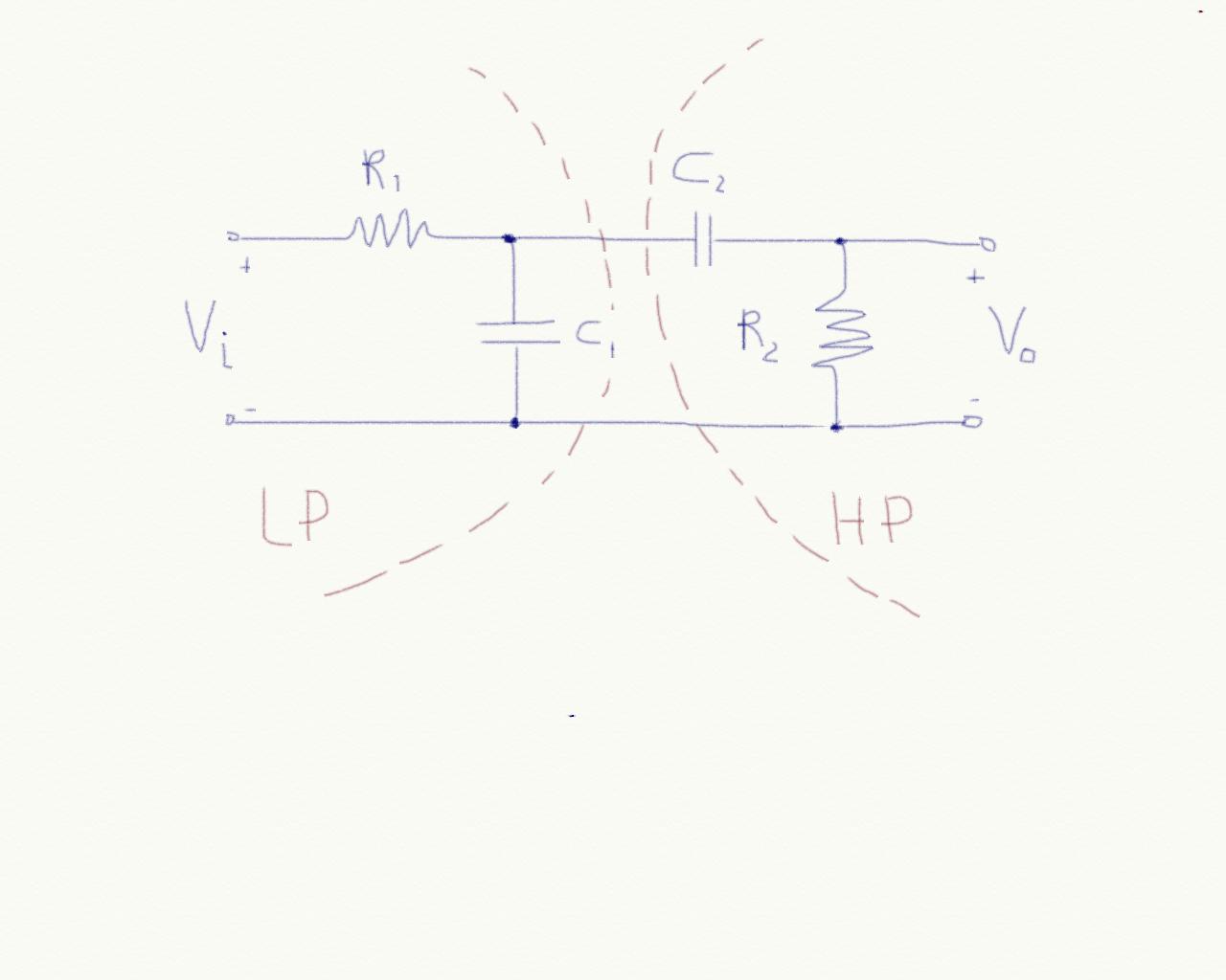 Figure 3
 If you compute Vo/Vi, which we name transfer function, then you could in principle draw the graph of the amplitude of this function versus frequency. This is not difficult to do and I suggest you to try to apply whatever analysis method you want to find the transfer function. You will notice that this system is a second order system (the equation is a second order differential equation). This is correct since it would not be possible to build a bandpass filter with a first order circuit only.
The bandwidth can then be computed by finding the solution to the equation
|Vo/Vi| = 1/sqrt(2)
which has two solutions for this circuit.
You may think that another way of computing the bandwidth is (naively) computing f0 and f1 for the low pass and high pass filter and finally compute their difference. This method would not work because the two circuits are connected in a cascade, so they influence each other. We should consider this interaction.
How can we separate the two circuits? We need a sort of buffer!
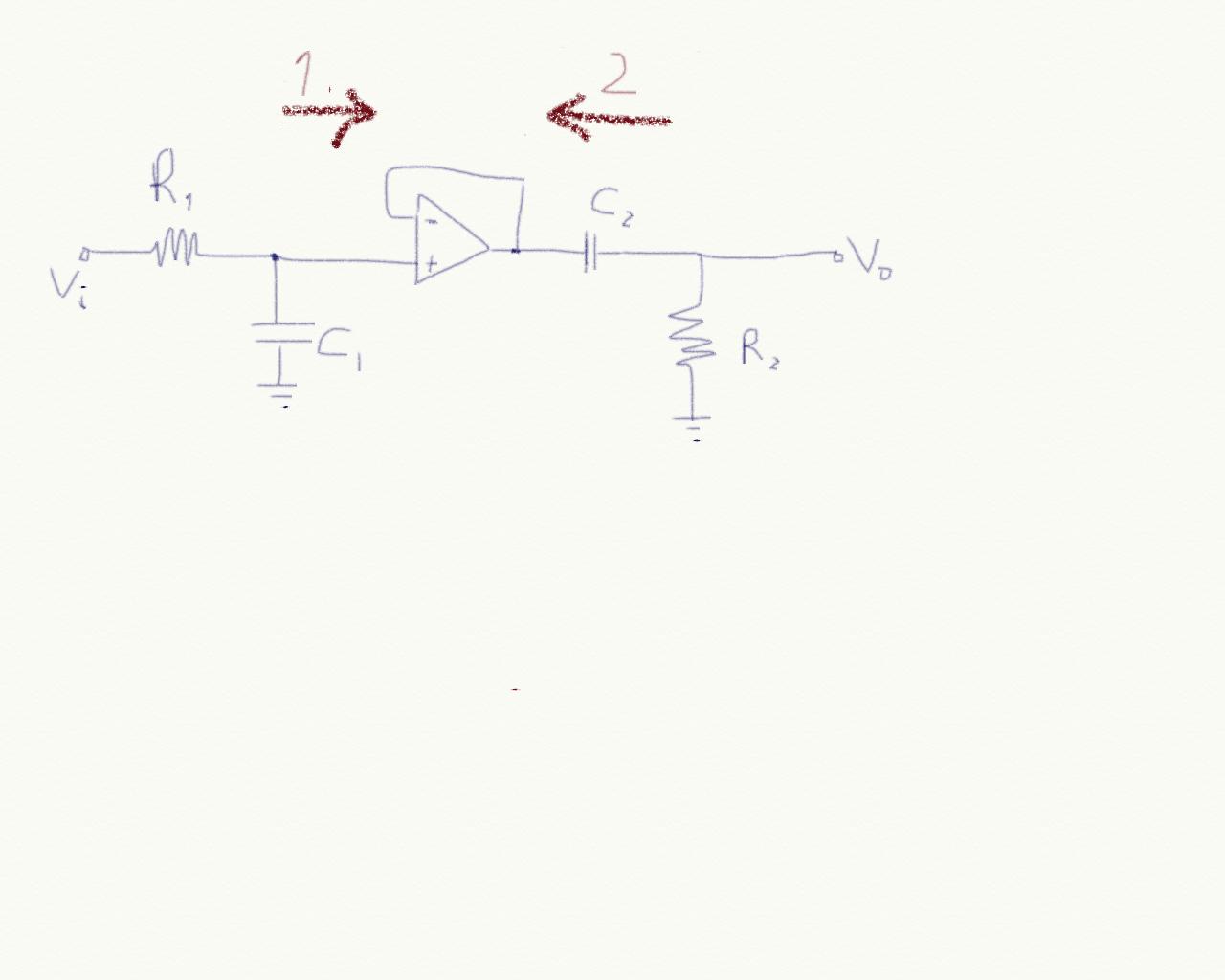 Figure 4
 Figure 4 shows how we can separate the two circuit in a very simple way. Looking from 1, the voltage follower is like an open circuit so it is possible to analyze the low pass filter as we did in class. Looking from 2, the voltage follower is like an ideal voltage source (whose value is the same as the voltage follower input which is the same as the low pass filter output).
Pre-lab (Analysis)
We want to implement a bandpass filter with f0 = 20Hz and f1 = 20Kz.
Q1)Find the values of R1, C1, R2, C2 Using the version of spice that you want, you should be able to describe the circuit and simulate it.
Q2)Describe the circuit using Spice.
Q3)Set an AC analysis to verify the cutoff frequencies.
I know that the spice part is not easy, but another thing that engineers are supposed to be able to do is to read manuals. So please read the spice manual to understand how to use components.
For the op amp you can use whatever model you want. I suggest to use something like uA741 or LM107. These op amps also need power supply (dual) so in the spice netlist you should also consider this and instance two dc sources.
I suggest you to use 5Spice which has a very simple graphical interface.
Lab (experiments)
First of all build the circuit. Open your spice simulation in order to have a reference!
Now you have to draw the transfer function. Use the function generator to generate a sine wave at different frequencies and for each frequency observe the output peak-to-peak voltage. Build up a table and the graph corresponding to it. Verify that experiment ad simulation match.
Report
As usual you should describe your experiment:
- What is the experiment setting: components used, their values etc.
- what are the stimuli that you are using: this also includes a description of the experiments that you are planning to do in order to claim that your circuit works!
- what is the result that you are getting
- What are the conclusions