EE40 Summer '04, Lab6
Introduction
In this lab you will start to build a tone controller for audio applications.
The building blocks that you will use are low pass and high pass filter and the summing amplifier.
Figure 1 shows graphically what happens in the frequency domain if you add the output of a low pass filter and an high pass filter.
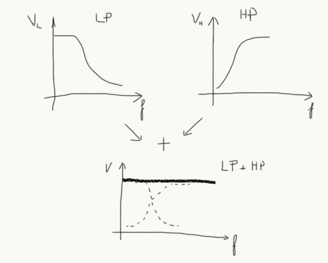 Figure 1
 You can set the cutoff frequencies of the two filters in order to have a flat transfer function.
Building a tone controller means building a systems that can weight the sum of the low pass filter output and the high pass filter output:
V= k1*VL + k2*VH
We have built a summing amplifier already so in principle we know how to build a tone controller. The system we want to build is sketched in figure 2.
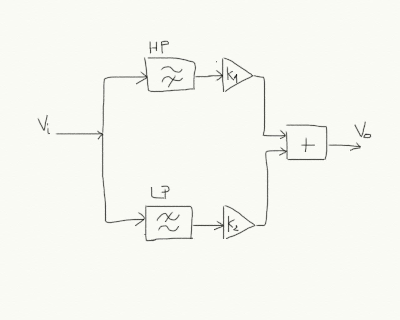 Figure 2
 This lab focuses on the two filters. In lab 7 we will put everything together.
We start with the high pass filter. We use an operational amplifier connected like in figure 3.
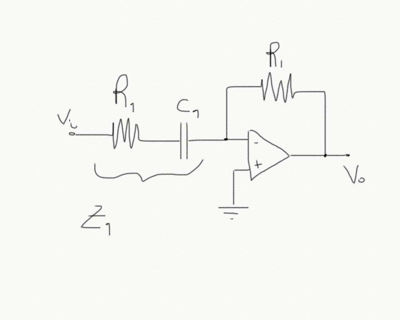 Figure 3
 The impedance is defined as the ratio V(s)/I(s), the voltage and the current in the Laplace domain. As we have seen in class, it correspond to consider capacitors as resistors of value 1/sC. So in this case:
Z1=R1 + 1/(s*C1) = (1 + s*C1*R1)/(s*C1)
The gain of the operational amplifier in the laplace domain is then:
G1(s) = -R1/Z1 = s*R1*C1/(1+s*R1*C1)
If you set s=j*2*pi*f (where pi is the greek p) and you compute the abs(G1(s)) then you will find the usual high pass filter function. The cutoff frequency is f1 = 1/(2 * pi * R1 * C1)
A low pass filter looks like in figure 4.
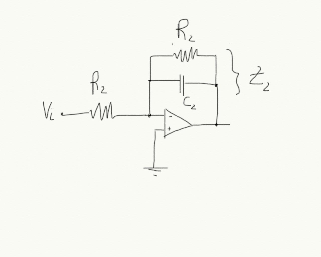 Figure 4
 Let's compute the impedance of the feedback branch again:
Z2 = R2 // 1/(s*C2) = (R2 * 1/(s*C2))/(R2 + 1/(s*C2)) = R2/(1 + s*C2*R2)
And the amplifier gain in the Laplace domain is:
G(s) = - 1/(1 + s*C2*R2)
that you should recognize to be a low pass filter. The cutoff frequency is f2=1/(2 *pi * R2 *C2).
Pre-lab
Q1)Compute the values of R1,C1 and R2,C2 in order to have cutoff frequencies f1 = 20KHz and f2=40Hz.
Q2)Use Spice to build a model for both filters and verify that your components values work.
Lab
At this point you should know how to build the circuits and test that simulations and experiments work.
Connect the two filters in cascade LP->HP. Measure the two cutoff frequencies like in lab4.
Report
As usual you should describe your experiment:
- What is the experiment setting: components used, their values etc.
- what are the stimuli that you are using: this also includes a description of the experiments that you are planning to do in order to claim that your circuit works!
- what is the result that you are getting
- What are the conclusions
You have to answer this questions which is very important:
Q3)In the series connection of low pass filter and high pass filter, do the cutoff frequencies change form the original computed f1 and f2?
Q4) And if they change, what, do you think, is the reason?