EE40 Summer '04, Lab9
Notation for this lab:
X_{a} means X subscript a
Introduction
This lab will be on rectifiers. These circuits are used mostly in power suppliers. The reason can be graphically described as in figure 1.
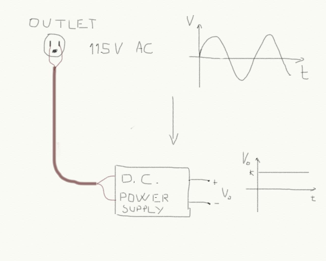 Figure 1
 The output voltage from an outlet is a sinusoidal waveform. For many electronic devices we need a continuous stable voltage which we refer to as DC.
For instance, to charge the battery of your mobile phone you need a charger whose output voltage is a constant DC voltage with a certain value.
The first step to do is to remove the negative part of the sinusoid. This can be done using diodes in a very easy way. There are many implementation of rectifier and in this lab we will focus on two of them only: the half way rectifier and the diodes bridge.
In this lab you will not use the transformer that you have in the kit but only the function generator. First of all look at figure 2 for a practical view of a diode.
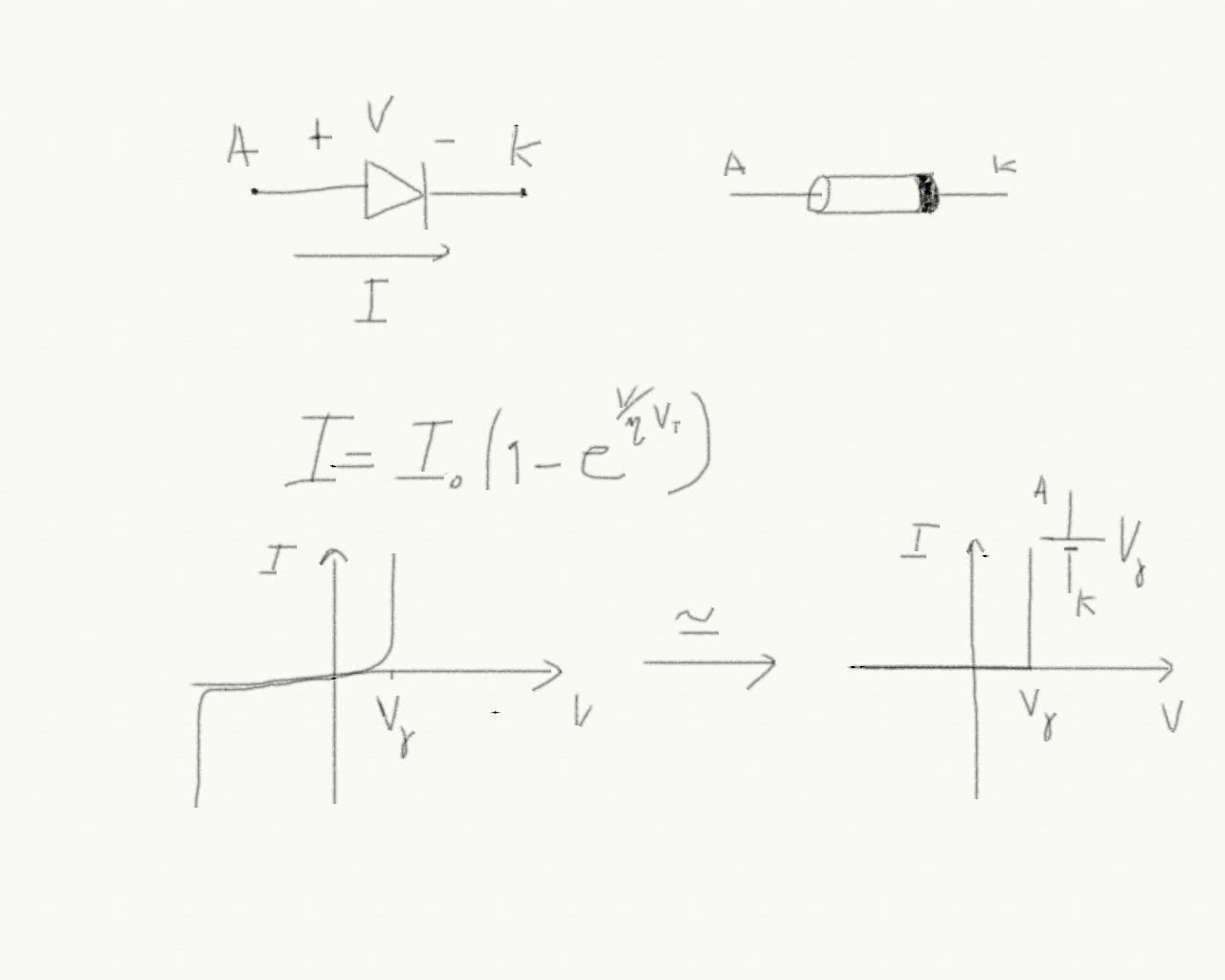 Figure 2
 You probably know the theory already. A diode is a two pins components: A is called anode and K is called cathode. A real life diode is a small cylinder with two pins where the cathode is marked clearly with a line. Please check the connections of this two pins before applying the voltage source because if you reverse the diode and if the applied voltage is greater than the breakdown voltage, you will break the diode... and a new one has to be ordered by UCB (even if a diode costs nothing basically, we don't want to run out of diodes).
For this lab we can use the approximation of figure 2 and consider a diode an open circuit if it is in reverse bias, or a voltage source with value V_{gamma} if it is in forward polarization.
A diode can be used to rectify the AC signal like in figure 3.
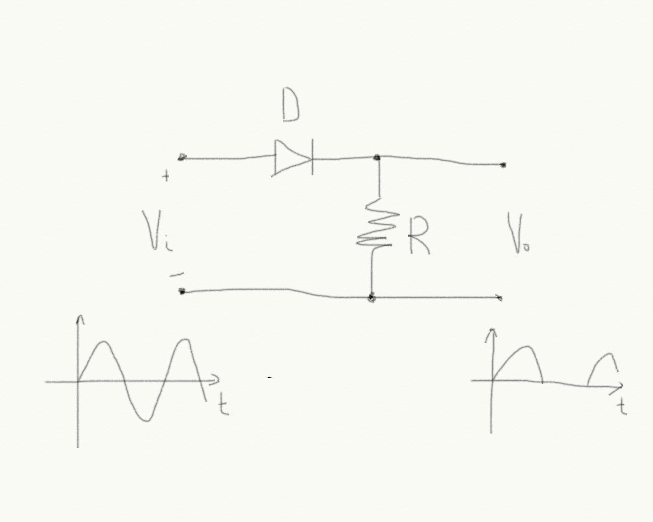 Figure 3
 This is an half wave rectifier. It is possible to build a circuit that rectifies both the positive and negative part of the input wave. A circuit that is able to do that is shown in figure 4.
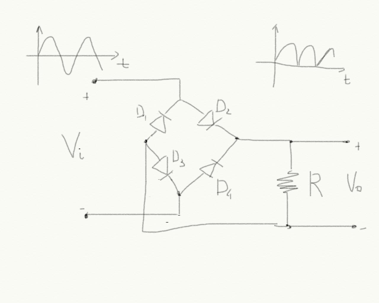 Figure 4
 This circuit is called diodes bridge.
Rectifiers can be used also to demodulate AM signals as we have seen in class. For this applications the diode V_{gamma} is too big because usually the input signal is very small. It is possible to build a precision rectifier using an operational amplifier like in figure 5.
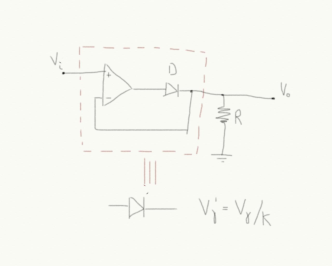 Figure 5
 A precision rectifier is equivalent to a diode whose threshold voltage V_{gamma}' is equal to the diode threshold voltage divided by the operational amplifier gain K.
Pre-lab
No pre-lab because there is a midterm coming up.
Lab
In this lab you have to draw the trans-characteristic of the three circuits of figures 3-4-5. Use a resistor R=1K.
The diode that you are going to use is the 1N4002. The data sheet is here (.pdf). A trans-characteristic is a graph of Vo as a function of Vi. In order to plot it, first build a table with two columns: one for Vi and the other for Vo. Then connect the input voltage of your circuit to the power supply that you have in the lab. Measure the output voltage for the following input voltages:
0.01V, 0.05V, 0.1V, 0.5V, 0.7V, 1V, 1.2V, 1.4V, 1.6V, 2V. Write the pairs (Vi,Vo) in your table. Finally draw a graph with Vi on the horizontal axis and Vo on the vertical axis. Draw a point for each pair in the table and finally connect the points.
Now, connect the input of your circuits to the function generator and the output to the scope. Use a sinusoidal input with amplitude sufficiently large to be able to observe an output at your circuit (you should be able to set such amplitude after drawing the trans-characteristic). The connections that you are supposed to use are shown in figure 6.
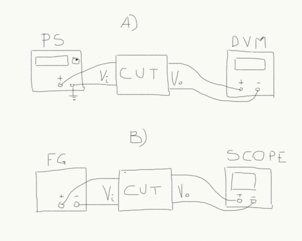 Figure 5
 CUT is the Circuit Under Test.
Connection A) is for the trans-characteristic. PS is the power supply (HP E3631A) and DVM is the digital voltmeter (HP 3401A).
Connection B) is for the sinusoidal input experiment. FG is the function generator.
Report
As usual you should describe your experiment:
- What is the experiment setting: components used, their values etc.
- what are the stimuli that you are using: this also includes a description of the experiments that you are planning to do in order to claim that your circuit works!
- what is the result that you are getting
- What are the conclusions
Q2) Why is the threshold of the precision rectifier lower that the threshold of the simple rectifier?
Q3) What is the minimum signal needed at the input of the diodes bridge in order to be able to see an output?
Q4) Justify your answer to question Q3.